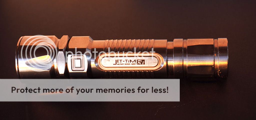
I have just completed an emitter swap on a Jetbeam Jet-III M Ti, which is a limited Ti version of the III M and had an R2 emitter.
The original emitters in these were supposedly hand selected and of a 'warm' tint. I never liked the tint and thought it more greenish yellow than warm, but the light itself I loved as it was just so well built.
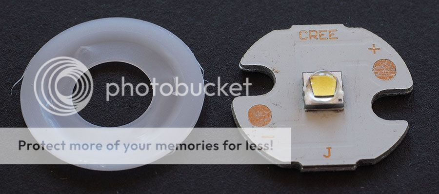
I recently decided to see if an emitter swap was a practical proposition. I was initially thinking in terms of an XML U2, but on measuring the current draw at the tail and finding it only about 0.9 A, I decided there wasn't much point and after doing a little research, decided on a Cree XP-G2 S2 with a neutral white tint. I ordered one on a 16mm Al board via eBay for about €3.7 ($4). Of course the original board was 15mm.

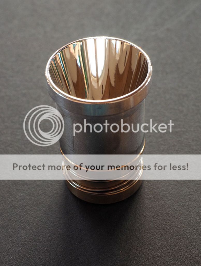
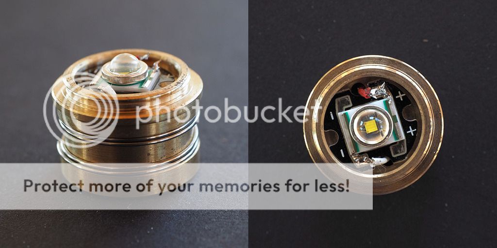
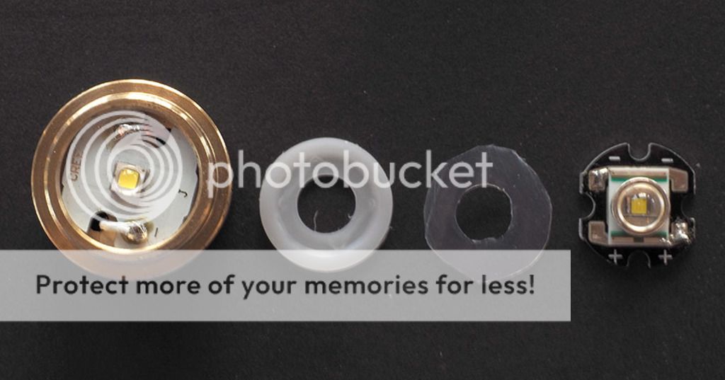
The whole process is pretty simple. You unscrew and remove the lens retaining ring. In my case the red O-ring came out also, stuck to the underside of the lens. The reflector-pill assembly then just slides out if you invert the head. The reflector screws onto the pill, so I just unscrewed it. There is a white plastic washer on the top of the pill through which the emitter dome protrudes. It is a friction fit and there is an inner lip on the pill to help retain it. I used a pointy sharp tool to pry it out. Doing so exposes the board, with red and white wires from below, soldered to the board. I Unsoldered those and removed the board. There was no thermal paste under the board.
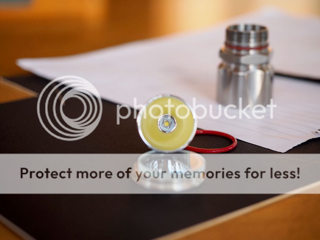
I downsized the new board using something like a Dremel and put it in place. I then screwed the reflector back on and sighting from an arm length back, checked that all of the reflector appeared a uniform yellow, reflecting the emitter phosphor. I had worried I might have to put a thin shim under the board as the original seemed far taller, and I did experiment with two shims, checking the uniformity of the reflection of the emitter, but decided the best result was achieved without a shim. This process required using my pointy tool - like a giant needle - to repeatedly move the board to centre the emitter when checking.
I put a small amount of thermal paste under the board and fitted it . In my case I had to reverse the bend on the ends of the wires as the solder pads were on the opposite sides of the cutouts vs the original. I used two small pieces of blu-tac to hold the board in place to the edges of the pill and refitted the reflector and used the tool to centre the emitter then unscrewed the reflector and soldered the wires to the appropriate polarity pads, then removed the blu-tac. I tried to refit the original plastic washer that stops the base of the reflector contacting the solder joints, but my joints seemed a bit bulky. The solder joints weren't marked from the base of the reflector and it fully seated so I decided to leave them and just made a thinner washer from some thick ptfe film. It's rough because the original washer slid around easily when I was trying to cut around it.
Then I just fitted the washer under the reflector and re-assembled the head, installed that and tested it.
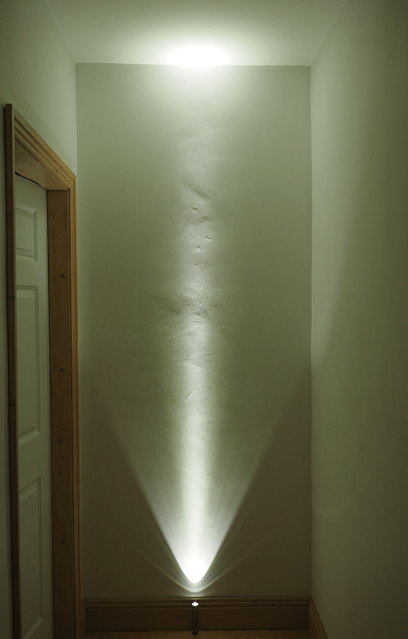
Initially I thought the focus wasn't quite right as there was a lot more spill around the hotspot, and though that is probably the case to a small extent, I decided the throw hadn't really been adversely effected and it was just the physical difference in the emitter packaging allowed for a much greater degree of spill and the greater output playing tricks. I far prefer the new beam pattern to the old and the tint is an immense improvement. All in all I am very pleased with how it turned out. The current draw is now 1A.