Another 7135 Driver Wiring Question

PaulH

Newly Enlightened
Joined
Oct 21, 2008
Messages
51
Location
Evesham, UK
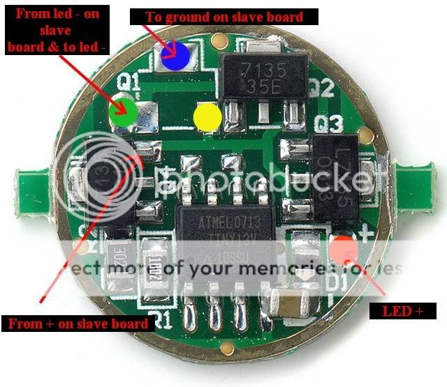
I've just received some 5 mode drivers from DX. They are completely different from the other ones that I have used.

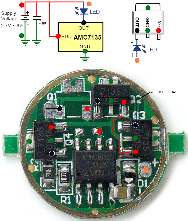
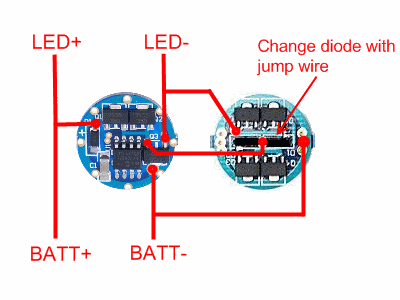
I would be extremely grateful if someone could tell me which of the pads (coloured in blue, green, yellow and red) correspond to LED+, LED-, Battery+, Battery-, and the +ve wire from the 1.4A 7135 board. I've included the picture from Stefan's thread as reference.

Many thanks.


Board delivered from DX today:

7135driverjs8.jpg


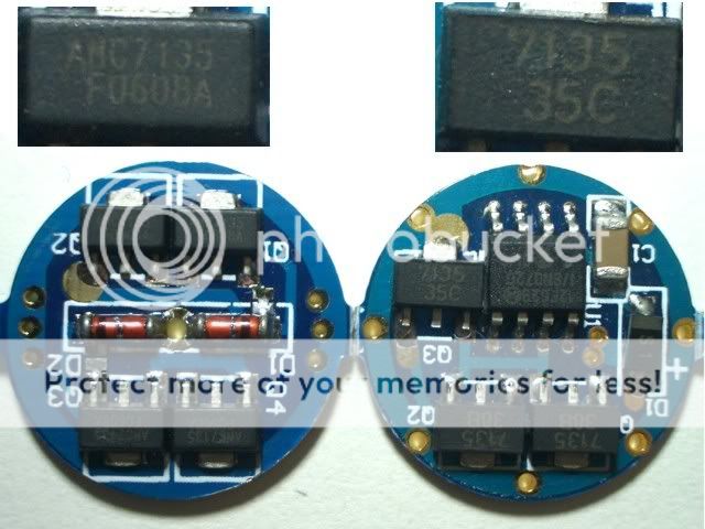
Previous Type (Also from DX):
P7-Multi-Drv01.gif
 

CampingLED

Enlightened
Joined
Nov 13, 2007
Messages
612
Location
South Africa
My guess, but it will be better if somebody else can confirm:

Yellow is the centre wire between the two boards (connects to centre of 4 x 7135 board)
Blue is battery minus -
Green is LED -
Red is LED & Battery +

Please note that this is my best guess based on how I interpret the new layout.
 

Isthereanybodyoutthere

Newly Enlightened
Joined
Jan 30, 2008
Messages
170
What sku number is that ??
It look like something i could use better than what i have
There is room for a fourth 7135 :naughty: that would turn the board into a 1,4 amp (at a small footprint ):twothumbs


BUT there is a strange thing about the board ?? two of the 7135 is one type but the third is different
AND in this thread
https://www.candlepowerforums.com/threads/201392&page=4
They show this
CIMG6390b.jpg


There was a problem because it is two different 7135`s
Some 7135/35C
Some 7135/fu806a


BUT On your board
ONE 7135/35E
+two 7135/0813

I have two 16 modes with 7135/0813
I have on my way from DX
10 x1,4 amp (4x 7135unknown )boards
+Two 16 modes 3x 7135unknown

Have any had any luck with mixing the different 7135`s ??

Just when i thought it was easy :sigh:
 
Last edited:

PaulH

Newly Enlightened
Joined
Oct 21, 2008
Messages
51
Location
Evesham, UK
Thanks CampingLED, I will give it a try tomorrow - unless anyone else wants to make any suggestions!!!

The new DX 1.4A 7135 boards are also slightly different - so I'm just hoping that they work ok together.

Oh... the Sku on the DX 5 mode 1A boards that I have is 6190 (http://www.dealextreme.com/details.dx/sku.6190). They are still showing the normal ones on a blue board.

They are currently out of stock - so goodness knows what I have been sent.
 

Isthereanybodyoutthere

Newly Enlightened
Joined
Jan 30, 2008
Messages
170
Thanks CampingLED, I will give it a try tomorrow - unless anyone else wants to make any suggestions!!!

The new DX 1.4A 7135 boards are also slightly different - so I'm just hoping that they work ok together.

Oh... the Sku on the DX 5 mode 1A boards that I have is 6190 (http://www.dealextreme.com/details.dx/sku.6190). They are still showing the normal ones on a blue board.

They are currently out of stock - so goodness knows what I have been sent.


Hey thats the same as i did order ,,except i did chose the 16 modes

You say the new 1,4 amp 7135 is different ??

Do the 7135`s on the 1,4 amp board have the same name /extension as the 7135`s on your (that arghh has two different)5 mode board ??,,if so they might work together ,,and hopefully mine that is coming to :twothumbs,,if not :duh2::thumbsdow:mecry::hairpull::scowl:
 

PaulH

Newly Enlightened
Joined
Oct 21, 2008
Messages
51
Location
Evesham, UK
Here is one of the 1.4A 7135 boards from DX (received yesterday).

The 7135 chips are all the L type (whatever that means), which is the same as the multi-mode driver, so I am hoping everything will work together.

I'll hopefully escape work this afternoon, and be able to get soldering... fingers crossed!
7135boardyr4.jpg
 

Isthereanybodyoutthere

Newly Enlightened
Joined
Jan 30, 2008
Messages
170
Well ,,, i also received my 16 mode 3x 7135 board ,,it should have been two ,,but DX only send one :shrug:

BUT :duh2: to make things more complicated ,my board has two L7135/0813+one 7135/35E

My two old boards did have 3x L7135/0813 :shrug:

But take a look at the multimode board in the photo from downloads thread
It has One 7135/35C and two 7135/38B

So by now we have
L7135/0813
7135/35C
7135/35E
7135/38B
7135/fu608A THAT WAS THE ONES THAT DIDNT WORK WITH THE MULTI BOARD IN DOWNLOADS THREAD

Whats up with all those different kinds :sssh::sick2:

I have on order 10X 4X7135 boards from DX ,,i really hope the are like yours L7135/0813
 

Casebrius

Newly Enlightened
Joined
Dec 4, 2006
Messages
168
Location
Cajun Heartland
has anyone figured thid board out? Very aggrevating for a novice modder,
zero information is available. I'm not an EE (I'm an ME), even if I was I think they should provide at least some type of schematic if they are going to sell a product unwired. It looks nothing like the advertised board either.
 

Roland Gama

Newly Enlightened
Joined
Aug 29, 2008
Messages
83
Photo-0002-3.jpg
[/IMG]
Here are pics about how it is done. Desolder the chip and the resistor of one board.It works very well.
Photo-0001-5.jpg
 

PaulH

Newly Enlightened
Joined
Oct 21, 2008
Messages
51
Location
Evesham, UK
Casebrius,

Stefan very kindly sent me his interpretation of the new MM driver boards. What type of sandwich are you making?

Hope this helps.

7135driverjs8kopiera.jpg
 

EL34

Newly Enlightened
Joined
Jan 11, 2009
Messages
65
AMC7135.gif

Found a schematic of a AMC7135 on the web and made this diagram.
Looks like the schematic is not exactly how the 7135s are used on the board in the picture.
I think just looking at the picture atht the ATMEL chip is driving the 7135's???
A real schematic of this board from the manufacturer would be the ticket.

I don't have one of the boards in front of me, they are on backorder and I am still waiting for mine.

I manufacture electrical items and I always need schematics and technical info on chips, etc. I can't believe DX doesn't have a spec sheet/schematic info tab on all these sorts of devices. Drives me nuts when you are trying to design something and need the spec's of a device.

Hope everything is correct on my diagram. I'll know for sure when I get my hands on a board. If anyone sees a problem, I'll fix or add something to the diagram.
 
Last edited:

Moddoo

Flashlight Enthusiast
Joined
Nov 19, 2008
Messages
1,243
Location
Minnesota
I just recieved some 7879 boards from DX. (3x7135 stated 980mA output)
They have the 7135 38B components.
inital testing with 1 on high mode, with a single 18650, at 4.05V, connected to an R2.
I am getting only .6A to the emitter, and .6A from the cell.
direct drive?

I am new to this stuff, but are the 38B components to blame?

I hope this isn't off topic.

I thought I would add to the 7135 data here.
 

Casebrius

Newly Enlightened
Joined
Dec 4, 2006
Messages
168
Location
Cajun Heartland
Casebrius,

Stefan very kindly sent me his interpretation of the new MM driver boards. What type of sandwich are you making?

Hope this helps.

Thanks. Just using it as a single board to drive a Q5 in an old C2. But if this thing isn't going to drive it sufficiently, I won't bother putting it in.
 

Isthereanybodyoutthere

Newly Enlightened
Joined
Jan 30, 2008
Messages
170
How much current do you get with he same 18650 direct drive ??
It could be the 18650 that cant deliver enough current ,and not the board
next measure how many volt runs over the R2 LED when its on (now you know how much the voltage sags under load )+ you know the Fv for the LED for the amp you did measure


I just recieved some 7879 boards from DX. (3x7135 stated 980mA output)
They have the 7135 38B components.
inital testing with 1 on high mode, with a single 18650, at 4.05V, connected to an R2.
I am getting only .6A to the emitter, and .6A from the cell.
direct drive?

I am new to this stuff, but are the 38B components to blame?

I hope this isn't off topic.

I thought I would add to the 7135 data here.
 

Isthereanybodyoutthere

Newly Enlightened
Joined
Jan 30, 2008
Messages
170
Ok i did just take a look at MY 7879 board
it is NOT like the one shown here
the one shown here is a 5 mode and i think the board is a NANJG
The 20 MODE 7879 is a LOCH board

And if you look at DX`s 7879 page and at the boar i have they are NOT the same ???

there is some small differences

One is if you hold the board ,so that the 8 leged chip is on top
then look just to the left of it you can see two unsoldered points
I have NOT made a test with my board ,,YET , but i think those pads/points could be there to be bridged to get number 3, 7135 chip to work

in other words it could be that the board is a 700 mamp until you bridge those points
Just like some of the 1400mamp 7135 single mode boards are /was

Thanks. Just using it as a single board to drive a Q5 in an old C2. But if this thing isn't going to drive it sufficiently, I won't bother putting it in.
 

Moddoo

Flashlight Enthusiast
Joined
Nov 19, 2008
Messages
1,243
Location
Minnesota
How much current do you get with he same 18650 direct drive ??
It could be the 18650 that cant deliver enough current ,and not the board
next measure how many volt runs over the R2 LED when its on (now you know how much the voltage sags under load )+ you know the Fv for the LED for the amp you did measure

Thank you for commenting on this.
It seems that I have an emitter issue, not a driver issue.
on another fresh cell @ 4.1V
the R2 is pulling .7A direct, and .67A with driver, Fv is 3.9V
A Q5 that I have is 1.6A direct, and 1.05A with driver, Fv is 3.6V

I need to test a few more emitters I have here.

It looks like the 7879 drivers are working fine.
Here is a pic of one of the 7879s.

7135driver.jpg
 

kramer5150

Flashaholic
Joined
Sep 6, 2005
Messages
6,328
Location
Palo Alto, CA
I just got some of these as well... DX:7612, all 3 are slightly different and none look like the ones pictured on DX... LOL.

Anyways I want to mod 2 of them up to ~1.3A output, by adding a 4th 7135 driver, per the pic below. by transplanting parts from the donor board.

-Can I just transplant an L7135-0813 from the donor board onto each recipient at "A" and "B"??
-If I do that, could the donor board still be used to drive a long running low-low output (emergency) type of light?

dx6190cs8.png


Thanks OP for creating this thread, and thanks in advance for all who reply.

:popcorn:
 
Last edited:

Moddoo

Flashlight Enthusiast
Joined
Nov 19, 2008
Messages
1,243
Location
Minnesota
Kramer,
I just had to try it.
I moved a 7135 from one board to another. like your diagram shows
(empty spot on my board is in the lower right in my pic)
It works. 1.37A output.
The donor board was .7a output afterwards.
I then removed the 7135 on the right side of my pic.
Donor board - 0Amps:(
I may need to jump something to get it going again.

FYI, it is really easy to overheat these tiny components with the soldering iron.
be careful.
 

kramer5150

Flashaholic
Joined
Sep 6, 2005
Messages
6,328
Location
Palo Alto, CA
Great thanks Gents!! With that 1400mah board always out of stock, this seems like the way to go.

Next question... can it be modded to run single mode? (Off-High)
 
Top