chimo
Flashlight Enthusiast
I didn't like the way my DSD charger terminated the charge cycle so I gave it a little surgery.
I used the LTC4054 chip from Linear Tech (same chip that is in AWR's Nano charger). Since the DSD will accept different cell sizes, I wanted to be able to vary the charge rate. I etched a board to allow 4 different charge currents, although, with the switches I had on hand, I only implemented it with 3 charge rates (approx 100, 300 and 500mA). This allows for charging cells down to the 10280 size.
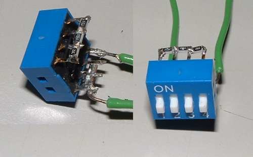
The LTC4054 is a CC/CV charger and terminates the charge when the charge current drops to c/10. The switch in the pic has 3 positions to select the charge rate. The LED flashes when power is applied with no cell, is on steady during the charge cycle and goes out when the charge is complete.
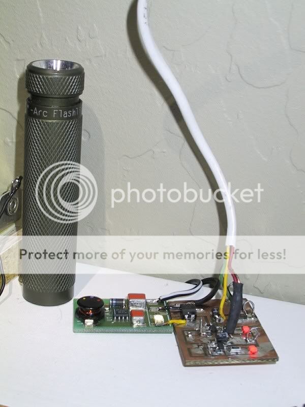
Before pic

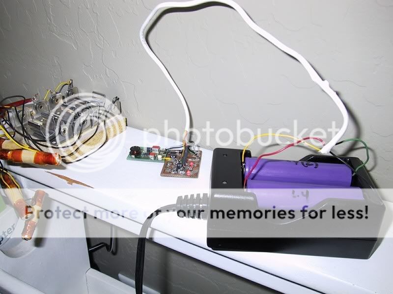
After Pics


Thanks for lookin'
Paul
I used the LTC4054 chip from Linear Tech (same chip that is in AWR's Nano charger). Since the DSD will accept different cell sizes, I wanted to be able to vary the charge rate. I etched a board to allow 4 different charge currents, although, with the switches I had on hand, I only implemented it with 3 charge rates (approx 100, 300 and 500mA). This allows for charging cells down to the 10280 size.
The LTC4054 is a CC/CV charger and terminates the charge when the charge current drops to c/10. The switch in the pic has 3 positions to select the charge rate. The LED flashes when power is applied with no cell, is on steady during the charge cycle and goes out when the charge is complete.
Before pic

After Pics


Thanks for lookin'
Paul
 ).
).  I couldn't help it
  ). I use one charger to charge the battery for my EDC B42 XR GT, and the other to charge the 17670 for my SF 6P with 3W Led module. I am also building an ROP/LE and I would like to just use one charger setup for the different batteries. Just a question.
")