Anatomy of an HID Xenon ballast

wulfgang

Newly Enlightened
Joined
Nov 10, 2006
Messages
40
Luke (liveforphysics) and I have an ongoing project to hack these and make them do different power levels and possibly change their shape (to fit into a flashlight tube). I thought some people might be interested to know what exactly is inside the little "black box."

I will post pics of our progress here if people are interested. Right now I am still working out the details, but maybe later I can post a rough schematic/guide to show how this thing works. Thanks to Luke for supplying the ballast that gave its life so that we might have... fun.:bow:

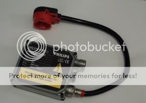
The first pic is just the top of the ballast after the potting is removed (big job!). The design is pretty standard: the 12 V input gets converted to around 90 V by a flyback converter and rectifier. Then that gets converted to a square-wave output by a full-bridge. The ignition circuit rides on the full-bridge, producing 25 kV pulses via a capacitor/spark-gap/transformer combo. This particular ballast uses current-mode control for the flyback. I have not yet found out how it senses lamp current.
top_markup.jpg

That's all for now.... more to come later...
 
Last edited:

liveforphysics

Enlightened
Joined
Dec 4, 2006
Messages
343
Wulfgang, you are my Hero! :knight:

I think details on de-potting would be awsome for people here, I can see that you obviously are a hell of a lot better at it than I am. ;)


I also have an idea. Could the current reading be accomplished by a seperate winding loop in the flyback transformer?

It looks like the factory ballast used available space pretty wisely, meaning its going to be a hell of a lot of work to make that fit into a reasonable sized round flashlight. If dont keep the hot-restrike feature, would this enable a much smaller sized ignition components to be used?

I am so happy to see these HID kits go to somebody that knows what they are doing. I was pretty foolish to think I would be able to do these mods all myself, I am very thankful to have found someone with your level of awsome skills .

I am excited looking forward to seeing more pics of the action!

Best Wishes!
:sssh: :rock:
 

wulfgang

Newly Enlightened
Joined
Nov 10, 2006
Messages
40
Instructions for de-potting:
1. get yourself a sharp instrument like a pick or small flathead screwdriver.
2. start digging.
3. check CPF for new posts
4. dig some more
5. check email
6. dig some more
7. go to bed
8. get up next morning
9. dig some more
10. go to step 3.

The flyback has only one primary and one secondary winding. There is already current sense on the flyback, and it would be entirely possible to use that as lamp current sense. But based on the app notes I've seen, it's not likely.

So you can see that the igniter takes up roughly 1/3 of the space on the board. Removing it could make the board small enough to put inside about a 2" tube. It could then be placed somewhere else in the tube, i.e. between the lamp and the ballast. Re-designing the ignitor for lower voltage would probably be more trouble than it is worth. This is a pulse design, and pulse transformers are somewhat difficult to design well. You'd end up with the same components but with a smaller transformer... not much use.

However, your lipo 4s2p pack is pretty large too. Put the ballast with the relocated ignitor into a 2" tube with that battery and you have a handle that's fatter but not quite as long as a 3D Mag with a runtime of 1.5 hours. Not bad, and waaay smaller (and sexier) than the handle on The Beast.
 
Last edited:

wulfgang

Newly Enlightened
Joined
Nov 10, 2006
Messages
40
I found the current sense resistors. They are on the bottom of the PCB:
bottom_markup.jpg


So with that, one can presumably change the output power of the ballast to under or overdrive a lamp. Underdriving is obviously safer, so I tried that first:
35Wvs24W.jpg


It should be fairly clear which one is the original 35W bulb. The other bulb is being driven at 24W (approx) by a modded ballast. I left the plastic cases attached to protect the bulbs, but they began to melt after about 3 minutes. The power is supplied from separate lithium polymer battery packs (11.1V, 2000 mAh). The pack for the 35W setup was beginning to get warm, but the 24W pack had not noticeably warmed up after 3 minutes.

I also tried to run a GE CMH 20W lamp with the modded ballast. It ignited, but would not keep running. The xenon in the automtive bulbs probably helps the voltage in these tubes rise rapidly to the steady 85V. My guess is that the CMH lamp (not a xenon lamp) probably is not capable of that fast a warmup, and the ballast may consider the cold lamp voltage a short circuit and shut everything down.

Anyway, the next step is to try overdriving the ballast to see if it explodes:duck:

That will have to wait until I can find some appropriate SMT resistors...

[EDIT] I should probably put in more details about the change... The parallel sense resistors are in series with the full bridge. They therefore pass all of the curren that goes into the lamp. By sensing the voltage across the resistor pack and the voltage across the full bridge, the controller can determine lamp power. After the lamp has warmed up, the controller will try to keep the sensed voltage (the voltage across the sense resistor) constant. So to change the lamp power, one only needs to change the sense resistor value. Reducing the sense resistance reduces the sense voltage -- the controller compensates by increasing the current (and power) to the lamp. Increasing the sense resistance has the opposite effect.
 
Last edited:

liveforphysics

Enlightened
Joined
Dec 4, 2006
Messages
343
If the bulb blows while finding overdriving limits, I will have another kit drop shipped to you :) Make a digi-key parts list for anything you need and email it to me.

Also, give me a paypal addy and go have a nice dinner with your wife on me. :D

Your work on this is just so awsome its hard to even belive its real.

Could you outline the area that people who use this very common ballast in automotive applications could scratch/de-pot to increase the output current of the ballast?

Right now my HID headlights are killer, but I would love to have something I could connect to my hi-beam switch that would enable the low-beam feature to become below 35w to protect other drivers eyes, while having the option for a highly overdriven output when on hi-beam. If you can figure out what resistance values would work well for this, and show me where to de-pot, I can do the rest.

Thanks a bunch!!! This is sooooo cooooool!!!! HID ballast reverse-engineering buddy!!!!!!!
 

wulfgang

Newly Enlightened
Joined
Nov 10, 2006
Messages
40
Ok, so I tried to bump up the power a bit. To do this, I just added more resistors in parallel. I tried to solder them on top of the original resistors, but as you can see in the pic below, it was not very easy to get the solder bridges to stick to the top resistors. I'm going to check out the ratings on these resistors and see if it would just be possible to replace the original 0.1 Ohm chips with 6 new 0.07 Ohm chips. That may not be possible because of the power ratings...

So to get to these resistors, you just take off the ballast cover. There are two covers... the one you are interested in is the sealed one. There will be a clear plastic cover underneath, and the PCB will be visible through gaps in the potting. If you carefully scrape some potting off, it should be easy to find these resistors. All of the ballasts are not the same (I have seen minor differences), but these resistors should be roughly the same at about 0.1 Ohm ("R10" markings on SMT chips).

To increase the power, I tried to add three resistors, giving 9/6 = 1.5x power increase (53W). Here's the pic of the mod:
mod_detail.jpg


Based on input current, I think at least one of the solder bridges is not touching the top resistor, so the ouput power is probably more like 45W than the planned 53W.

This time the difference isn't so obvious, but you can still see the power increase. The original ballast is still on the left; the modded one is on the right:
35Wvs45W.jpg

So to make a high/low beam switch, you would need to somehow switch these resistors remotely. I do not think that remotely locating them would be a good idea, though, because they are carrying high frequency current (probably 100 kHz or so). Approx. 400 mA passes through them after warm-up (much more before then). However, the three extra resistors required to reach 53W only carry 1/3 of the current, so it might be possible to connect/disconnect them using a small FET. Just an idea, of course. I am not sure where you'd put one... there's not much room between the PCB and the ballast cover.

I have a spare computer PSU, so I'm going to try to rig it to drive these ballasts so that I can do long term tests, i.e. run them overnight at high power and see if they make it.
 

wulfgang

Newly Enlightened
Joined
Nov 10, 2006
Messages
40
Actually, that little notch in the PCB next to the sense resistors looks like the perfect place to put either a higher wattage axial resistor or a small SMT FET and three more sense resistors....
 

2xTrinity

Flashlight Enthusiast
Joined
Dec 10, 2006
Messages
2,386
Location
California
Wow, if modifying the resistance on those sense resistors is all it takes to reliably change the brightness of HID lights, I wonder why we don't see more with dimmers? It should simply be a better of switching those out with variable resistors, which should be fairly easy for the OEM.
 

wulfgang

Newly Enlightened
Joined
Nov 10, 2006
Messages
40
It's because your headlights are not actually bright/dim. Rather, they are high/low beam. The idea with headlights is not to dim the light, but to instead project them lower so that they do not shine into oncoming traffic. That requires changing the projection pattern; you cannot change the pattern just by dimming the lamp.
 

2xTrinity

Flashlight Enthusiast
Joined
Dec 10, 2006
Messages
2,386
Location
California
wulfgang said:
It's because your headlights are not actually bright/dim. Rather, they are high/low beam. The idea with headlights is not to dim the light, but to instead project them lower so that they do not shine into oncoming traffic. That requires changing the projection pattern; you cannot change the pattern just by dimming the lamp.
I was not thinking so much of headlights (which I know use either multi-filament or rotating reflector assembly in the case of HID lights) so much as handheld HID lanterns where one might want dimmer output/longer runtime, or for fixed lighting applications using HID bulbs. Come to think of it, dimming the HID bulbs seems like it might work in places that require daytime running lights -- I know a lot of vehicles simply dim the halogen high-beam bulbs for that reason (although glare from those vehicles is especially annoying -- cars with separate running lights are better in that respect).
 
Last edited:

liveforphysics

Enlightened
Joined
Dec 4, 2006
Messages
343
At work today I will perform the MH ballast current boosting mod on my cars headlights. Thanks a bunch for the super easy guide! I'm thinking of just removing a few of the resistors it has now to drop power to 20w, then mounting a relay on the outside of the case with the coil toggled by the Hi-Beam power. The relay contacts will be connected across the Vsense resistor bridge with XX quanity of resistance in series with it.

I am assumeing logically that this works in an inverse liniar fashion with resistance, which should make the calculations quite easy. Could you confirm this to be correct for us?

Thanks a bunch for this project!!! This is truely the coolest modification I have seen on this entire forum.
 

wulfgang

Newly Enlightened
Joined
Nov 10, 2006
Messages
40
Yes, the controller will try to keep the voltage across the bridge the same, so for N identical resistors of resistance R in parallel (making R_total equivalent resistance) and for original power times a factor f:

P = V^2 / R_total

P = V^2 N / R

f P = V^2 f N / R

Since P, V^2, and R are constant, the modded power f P is proportional to f N. Thus for 50% more power you need 50% more resistors (of equal value to the original ones) and for 50% less power you need to remove 50% of the resistors.

If you have access to a high current meter, you might want to confirm power input levels... I can only do <10A for <30 secs with my meter. That doesn't give me time to watch the warm up current.

Of course if you have a way to measure lux that would be even better.
 

modamag

Flashlight Enthusiast
Joined
Aug 16, 2004
Messages
2,101
Location
Bay Area, CA
Wow! Really cool stuff guys. :twothumbs

Thanx! wulfgang for putting in plain English for us to see.
Now I have to revisit couple of my old projects.

BTW: that igniter on yours looks scary I'm more used to the separation of ballast & igniter for portable lighting application. I've seen some version where they separate the entire unit into four separate board and stacking them to "conserve" space.

Is this a CAR ballast?
 

yuandrew

Flashlight Enthusiast
Joined
Apr 12, 2003
Messages
1,323
Location
Chino Hills, CA

liveforphysics

Enlightened
Joined
Dec 4, 2006
Messages
343
yuandrew- You are in luck my friend. The ballast you are looking at all depotted above is the same ballast you show above as the philips LVQ212. I agree that it is the most common retrofit, which is why I sent them to wulfgang to tweak. It enables the most people to benifit from the tweaking related info.

Thanks for the pics!

Do you happen to have any specs reguarding how far they are able to overdrive these ballasts? Or perhaps at what point you begin to saturate and reach a diminishing returns point?
 

liveforphysics

Enlightened
Joined
Dec 4, 2006
Messages
343
wulfgang- Do you know the frequency these are switching current to the bulbs yet? I'm just guessing that it happens to be above the range which I could use a ceramic potted wire-coil type resistor with due to inductance lag issues? I have been digging around for carbon film type high power resistors in these resitance ratings and finding that I only have wirewrap types :(.

I am ready to impliment the power dropping and boosting system in my daily driver to replace the hi-low beam system. I was thinking of making the hi-beam be around 60w, and the low beams be around 15w or so to make it easy as possible on other drivers eyes at times when strong lighting is not required.

Let me know if you happen to know the low side threshold for the bulbs so I can set the low beams to that value.
 

Flummo

Newly Enlightened
Joined
Jul 14, 2006
Messages
72
Location
Sweden
Excellent work! So they're not as advanced as you might think... But still a bit too advanced for me to build myself. I guess I'll just wait for an integrated circuit to handle most of the job. ;)
 

wulfgang

Newly Enlightened
Joined
Nov 10, 2006
Messages
40
Yuandrew: Excellent pics! Some of those lights look interesting. I hadn't heard of HID Planet... will have to get over there and poke around.

liveforphysics: I forgot all about looking at these on the scope. I will try to get to that this evening and take some pics (I have an old school CRT scope), get the frequency, etc. But no, you can't use wirewounds. Only ceramic chips or axial carbons would work. And unfortunately, the UIUC electronics store does not carry anything below 1 Ohm. Right now I can work with the 6 spare chips from the sacrificial ballast, but they are so small I already lost two of them :(

You could fairly easily find out the lower limit of power by removing 1 chip at a time until it doesn't work anymore. I already removed 2, so you could start by removing 3 and go from there. That should already be half power.

Flummo: Actually, while they are not "advanced" per se, the control circuit is fairly complex and the component count is high. You're looking at quite a few functions that need to be implemented. There is the flyback controller and driver, the rectifier controller and driver, and the full-bridge controller with both low- and (level-shifted) high-side drivers. The lamp current controller has to provide enough voltage for the ignition circuit to charge up when the lamp is not lit, be able to detect a short circuit, be able to detect an open circuit (so nobody gets zapped), be able to ramp down the current during the warm-up period, stabilize the current after warm-up, and detect when the lamp has reached the end of its life. Each of these tasks is fairly easy by itself, but add them all together....

Anyway, there already IS an IC that handles most of the job. Check out the UCC3305. It handles all of the control mentioned above plus some of the driving. You would need to add lots of passives as well as the full-bridge driver and level-shift IC. It also does not have the ignitor.
 
Top