Powering LEDs

coolwaters

Newly Enlightened
Joined
Jul 5, 2007
Messages
123
iv have a voltage meter and it says the voltage is 3-3.2v and my luxeon K2 is running at 900mA. thats natural right? but the chart says at 3-3.2 the current should be less then 300mA.


also it is ok to drive a LED at a high voltage but low current? or restricted current?
 

Christexan

Enlightened
Joined
Sep 29, 2006
Messages
224
The chart is "typical" performance, and often out of date within a few months of release as production improvements roll through.
I have a triple Q2 Cree lighthead (pure copper PCB surface mount) which runs around 9.1V at 350mA (3.04V per emitter roughly) when specs at that current are 3.3V typical, 3.9 max. These have been measured with different multimeters and the measurements are consistent. At 700mA, they run at 9.9V (so 3.3V per emitter average), spec sheet says 3.5V at that current, this is why it is stressed so often use a CURRENT regulated source, not a voltage regulated source, I can hit 1A right at 10.0V with these particular 3 (not hand-picked, I got 10, and these were #s 2-4 (1 was used elsewhere). If I ran at the "specsheet" voltage of 3.7V per emitter without current limiting, I'd likely incinerate them within seconds (benchtop regulated supply capable of 3A, I DO use both voltage and current limits, but without the current knob....). Oh, all figures measured within a few seconds of turn on (as soon as the reading appears), not after heating Vf drop effects can take place.
Anyhow, long story short, spec sheets are "typical" figures and Cree especially seems to be doing much better at being BELOW typical in my experience than at or above it, at least with the P4 and Q2s that I've used. Lumileds/Luxeon is probably the same.
 

coolwaters

Newly Enlightened
Joined
Jul 5, 2007
Messages
123
what? at higher amps they were drawing more voltages?

the only thing i dont like about the LEDs is y do they have to pick such a random number? 3.4v?? u know how hard that is to power them with 12v? which is pretty common...
 

Bunk3r

Newly Enlightened
Joined
Jun 14, 2007
Messages
112
Location
Hull, England
note if the current is pulsed into the LED (which is the case with PWM and often with a boost or buck circuit depending on how much smoothing is added) then cheap meters will misread the results.

the only thing i dont like about the LEDs is y do they have to pick such a random number? 3.4v?? u know how hard that is to power them with 12v? which is pretty common...
they didnt pick the voltage, its to do with the bandgap /energy of photon at the emmited wavelength (but Im not going to go into that now).
 

evan9162

Flashlight Enthusiast
Joined
Apr 18, 2002
Messages
2,639
Location
Boise, ID
You must stop thinking of LEDs like light bulbs. LEDs are current devices, not voltage devices. You must feed them a regulated amount of current, not voltage. The Vf is not a value telling you how much voltage to feed them. It is an approximate value as to how much voltage will drop across the LED when the rated current flows through it. With LEDs, current is the independent variable, not voltage.

Read these:
http://candlepowerforums.com/vb/showthread.php?t=72528
http://candlepowerforums.com/vb/showthread.php?t=77221

And look at the graphs in this thread to understand the difference between how LEDs and regular bulbs respond to being driven from a voltage source:

http://candlepowerforums.com/vb/showthread.php?t=84411
 

coolwaters

Newly Enlightened
Joined
Jul 5, 2007
Messages
123
i was told that if the voltage was right then the LEDs will only draw
as much amperage as show on the chart.

but when i used a 12v 5amp transformer to power 4 Luxeon K2 LEDs in series (each should have about 3v) the chart said that it should only take in about 200-300mA at 3v but with pretty accurate voltage meter it says the LEDs are drawing 800mA...

im using a stabilized LED ballast so does that mean i dont need regulators since the current and voltage is already constant?
 

evan9162

Flashlight Enthusiast
Joined
Apr 18, 2002
Messages
2,639
Location
Boise, ID
i was told that if the voltage was right then the LEDs will only draw
as much amperage as show on the chart.

You were grossly misinformed. The Vf of an LED varies on an individual basis, and also depends on the temperature. The I/V curve is only a typical example, and is not intended to represent exact data to be used. In the real world, that I/V curve constantly moves around due to temperature, and is different for each individual LED. The chart cannot be used to figure out how to drive an LED with a voltate regulated source. It is only intended to give an idea of how much voltage drop would be required, so the driver/power supply can be designed with that in mind.


but when i used a 12v 5amp transformer to power 4 Luxeon K2 LEDs in series (each should have about 3v) the chart said that it should only take in about 200-300mA at 3v but with pretty accurate voltage meter it says the LEDs are drawing 800mA...

Was it a transformer, or regulated 12V power supply?

If it was an unregulated 12V transformer, then it would output about 16V with no load. Only with a 5A load would the output drop down to 12V. Thus, the output voltage was much higher than 12V with only 800mA being drawn from it.


im using a stabilized LED ballast so does that mean i dont need regulators since the current and voltage is already constant?

I'm not sure what you mean. If it is a proper LED driver (like a Xitanium or Microdriver) then that's all you need. If you're using a generic regulated DC power supply that only regulates voltage, than you need a proper current regulator, or need to pick out the proper current limiting resistor.
 

coolwaters

Newly Enlightened
Joined
Jul 5, 2007
Messages
123
I'm not sure what you mean. If it is a proper LED driver (like a Xitanium or Microdriver) then that's all you need. If you're using a generic regulated DC power supply that only regulates voltage, than you need a proper current regulator, or need to pick out the proper current limiting resistor.


thanks for clarifying things.

yes the driver is Xitanium.


what kind of regulators do u people recommend me getting?

i just want to bring the current down to 350mA and 700mA.

thank you for your help.
 

evan9162

Flashlight Enthusiast
Joined
Apr 18, 2002
Messages
2,639
Location
Boise, ID
thanks for clarifying things.

yes the driver is Xitanium.


what kind of regulators do u people recommend me getting?

i just want to bring the current down to 350mA and 700mA.

thank you for your help.


The Xitanium is perfect. No need for anything else. I highly recommend these kinds of drivers, as they power the LED appropriately, and are extremely simple to use.
 

coolwaters

Newly Enlightened
Joined
Jul 5, 2007
Messages
123
lol then how do u use them??

so far i only successfully used them with K2 rated up to 1500mA. but i had to wire them in series of 4 so each will draw about 3v anymore will blow up.
wire 3 in series was out of the question...


btw the Xitanium is 12v and 5A.
 

evan9162

Flashlight Enthusiast
Joined
Apr 18, 2002
Messages
2,639
Location
Boise, ID
Which model did you get? The Xitaniums I'm familiar with are current regulated, which means you can connect one or more LEDs in series directly to the output, and the driver keeps the same current flowing, regardless of how many LEDs are connected (up to a limit, of course).

It sounds like the driver you have is not current regulated.

[edit]

I've found a 12V, 5A Xitanium driver. Number LED120A0012V50F. From the description:
This 60 watt driver provides a constant voltage output for operating LED systems requiring a nominal 12VDC voltage.

This driver is not intended for direct connection of regular LEDs. It is intended for LED systems/arrays already set up to run from 12VDC. In fact, it's simply a 12VDC power supply with a 5A current limit. So your LED array would need to draw 5A nominally for this driver to be appropriate.

The Xitanium you really want is this one:
LED120A0700C24F (http://www.ledcentral.com/DisplayProduct.aspx?id=14&p=0&rid=P&appid=5)
700mA output, up to 24V

or this one:

LED120A0024V10F (http://www.ledcentral.com/DisplayProduct.aspx?id=10&p=0&rid=P&appid=5)
1050mA output, up to 24V
 
Last edited:

Curious_character

Flashlight Enthusiast
Joined
Nov 10, 2006
Messages
1,211
This little writeup is the beginning of a tutorial I've been working on. It might help explain things, so I'll post this part early. Feedback is welcome.

c_c

------------


Why is it important to regulate or limit LED current? Why can't we always just connect an LED directly to a battery like we do with incandescent bulbs?

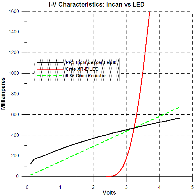
The answer is that LEDs behave very differently from incandescent bulbs with respect to voltage and current. The following graph illustrates the difference.
PR3_and_Cree_IV.gif


The black line shows the relationship between voltage and current of a PR3 3-cell incandescent flashlight bulb. The red line is a Cree XR-E LED mounted on a large heat sink. Notice the dramatic difference in slope and shape of the two curves. The curve of a 6.85 ohm resistor is shown for comparison. As you can see, neither the incandescent bulb nor the LED behaves like a resistor, and they behave vastly differently from each other.

Consider what happens to the current of each light emitter when the voltage changes, say from 3.5 to 3.0 volts, a change of about 14%. At 3.5 volts, the PR3 incandescent bulb current is 490 mA and the LED current is 1000 mA. At 3.0 volts, the PR3 current is 450 mA , or about 8% less than it was at 3.5 volts. The LED current is about 175 mA at 3.0 volts, or about 82% less than it was at 3.5 volts! For comparison, the resistor current drops by the same fraction as the voltage, or about 14%. So while the incandescent current is only about half as sensitive to voltage as a plain resistor (at this voltage range), the LED current is nearly six times as sensitive as a resistor, and ten times as sensitive as the incandescent bulb. Those particular ratios are valid only for the 3.0 – 3.5 volt range, but the extreme sensitivity of LED current to voltage holds for most of its common operation range. The steeper (more vertical) the I-V curve, the more sensitive the current will be to voltage changes. You can see that the LED curve is much steeper than the PR3 curve except at very low LED current, showing its much greater sensitivity.

Compounding the difficulty of direct connection of an LED with a battery is that the LED voltage is sensitive to temperature. For a given current, the voltage decreases about 2 mV for every one degree C in chip temperature rise. A few tens of degrees isn't an unusual temperature rise for an LED in a flashlight, so a voltage shift of 100 mV or so isn't uncommon. The effect is the same as shifting the LED I-V curve 0.1 volt to the left. An LED running at 1000 mA at room temperature would end up drawing about 1300 mA when warmed up due to a mere 100 mV voltage decrease. And finally, each individual LED is a bit different. So if you were to connect various LEDs to the same fixed voltage, the currents could be widely different. This is shown very clearly here. (Note that the axes are reversed relative to the graph above.)


The light output from an LED is approximately proportional to the current through it. (It's not quite proportional because the efficiency decreases with increasing current except at extremely low current levels. But proportionality is a reasonable approximation for our purposes.) Because the output is about proportional to the current, it varies dramatically with small changes in voltage. While it's possible to regulate the LED voltage, the current and therefore output would vary considerably from LED to LED, and could vary a great deal as the LED heats up. Keeping the LED current reasonably constant is therefore highly preferable, since it results in much more predictable and stable light output. There are three common ways to regulate the LED current to various degrees:

  • Electronic current regulator. This is the most effective but most expensive solution. However, electronic regulators will function only over some range of input voltage. So some lights having an electronic regulator will go into a mode resembling direct drive as the battery voltage drops below a certain level or, in some cases, when the voltage is above some level.
  • Series resistor. A resistor in series with a higher voltage than otherwise necessary has the property of reducing the sensitivity of current to changes in voltage. The larger the resistor and higher the supply voltage, the more stable the current will be. This approach is simple and inexpensive, but requires a higher voltage battery. And power used by the resistor is lost as heat rather than contributing to the light output. This method will be discussed in detail in Part 2.
  • Depend on the battery internal resistance. This is the method used by keychain squeeze lights and many inexpensive LED flashlights which use three AAA cells. Of the three methods, this is the simplest and least expensive, but it results in relatively poor current regulation and consequent varying light output as the battery discharges.
 

Mash

Enlightened
Joined
Dec 18, 2006
Messages
378
Ive been studying the xitanium data sheets extensively. Their naming and models are very confusing! (beware of the Constant voltage 12v and 24v versions! The ones we need to talk about are called XITANIUM POWER LED DRIVERS).
We will ignore the constant voltage ones, which are intended for strips etc and stick to the CC LED drivers.

HOWEVER this is where it gets confusing:
The CC ones usually have a max voltage output of 24Vs. Thats why in their circuit diagrams you see a maximum of 6 LEDs in series for each leg. BUT in some datasheets there is no minimum voltage specified, and in other datasheets, some of them have a minimum voltage output of 14Vs. However, in this example, the circuit diagram sez you can run it with only one led on each leg. Which would mean each led receiving 14Vs! Instaboom time indeed!

If they are TRUE CC drivers, you should be able to use a single LED, and parallel additional ones to distribute the current, but the daatasheets give conflicting answers. Can anyone who has experience, shed a light on this type of situation?


The more I look into xitaniums, the more possibility I see, for example the highest number of leds per driver I found, at 54! However their product range is very confused and badly presented.
 
Last edited:

Curious_character

Flashlight Enthusiast
Joined
Nov 10, 2006
Messages
1,211
Ive been looking at xitanium data sheets. Their naming and models are very confusing!
We will ignore the constant voltage ones, which are intended for strips etc and stick to the CC LED drivers.

HOWEVER this is where it gets confusing:
The CC ones usually have a max voltage output of 24Vs. Thats why in their circuit diagrams you see a maximum of 6 LEDs in series for each leg. BUT in some datasheets there is no minimum voltage specified, and in other datasheets, some of them have a minimum voltage output of 14Vs. However, in this example, the circuit diagram sez you can run it with only one led on each leg. Which would mean each led receiving 14Vs! Instaboom time indeed!
Can anyone who has experience, shed a light on this type of situation?
The more I look into xitaniums, the more possibility I see, for example the highest number of leds per driver I found, at 54! However their product range is very confused and badly presented.
I think you're misunderstanding how a constant current source works. If I'm wrong, I apologize for the unnecessary posting. I remember a very long time ago having a lot of trouble getting the hang of current sources, so it's easy to understand when others do.

First a brief review of a constant voltage source, since most people are more familiar with these than constant current sources. A perfect, ideal constant voltage source would produce a constant voltage across any load. The current is determined entirely by the effective resistance of the load, and our perfect source can deliver whatever current is necessary to make the voltage the correct value. In practice, a constant voltage source has a current limit -- the maximum current it can deliver. The power it delivers is the voltage times the current, and a real source can deliver only so much. So a real voltage source always has a specification telling the maximum current it can deliver. As an example, if you connect the LED in the graph I posted to a constant 3.5 volt source, it would draw 1 A -- until it heated up, which would cause the current to rise a great deal. But the voltage would stay at 3.5 volts. Assuming, that is, that the source's current limit is greater than the current the LED is attempting to draw at 3.5 volts. But if you connect the 3.5 volt source to a 0.001 ohm resistor, it wouldn't deliver 3.5 volts, unless it had a current limit of at least 3500 amps. Leaving the output short circuited won't result in the specified voltage, because getting that voltage would require the source to produce an infinite current. If you begin with a very low value resistor as a load, you'll get some finite current (less than or equal to the current limit) and almost no voltage. If you increase the resistor value, the voltage will increase. At some point, the voltage will reach its regulated value. The current at that point is the current limit for the source.

A constant current source is just about the opposite in every way. An explanation of how one works can be done by little more than reversing the words "current" and "voltage" and "open circuit" and "short circuit", in the voltage source explanation: A perfect, ideal constant current source would produce a constant current through any load. The voltage is determined entirely by the effective resistance of the load, and our perfect source can produce whatever voltage is necessary to make the current the correct value. In practice, a constant current source has a voltage compliance -- the maximum voltage it can deliver. The power it delivers is the current times the voltage, and a real source can deliver only so much. So a real current source always has a specification telling the maximum voltage it can deliver. As an example, if you connect the LED in the graph I posted to a constant 1 A source, the LED voltage would be 3.5 volts -- until it heated up, which would cause the voltage to drop slightly. But the current would stay at 1 amp. Assuming, that is, that the source's voltage compliance is greater than the voltage across the LED when it has 1 A of current through it. But if you connect the 1 A source to a 1 kohm (1,000 ohm) resistor, it wouldn't deliver 1 amp -- unless it had a voltage compliance of at least 1,000 volts. Leaving the output open circuited won't result in the specified current, because getting that current would require the source to produce an infinite voltage. If you begin with a very high value resistor as a load, you'll get some finite voltage (less than or equal to the voltage compliance) and almost no current. If you decrease the resistor value, the current will increase. At some point, the current will reach its regulated value. The voltage at that point is the (maximum) voltage compliance for the source.

So you see, the output voltage specification of a current source isn't a voltage it will force across the load -- it's the minimum, maximum, or range of output voltages (which are dictated by the load) over which it will produce its specified current. The current source won't force the LED to have any particular voltage across it -- the LED itself determines what voltage it will have, given the supplied current.

Both current and voltage sources (real ones, that is, not ideal ones) have some limitation on supply voltage as well, and often there's a limit on the maximum or minimum voltage between input and output. These are dictated by the circuit design. Outside those limits, either the circuit will fail to deliver a constant current or voltage, or it'll be damaged.

c_c
 

Mash

Enlightened
Joined
Dec 18, 2006
Messages
378
Thank you for your detailed explanation! I was alluding more to the MINIMUM voltage of the CC sources than maximum, due to the instaflash factor.
I think the problem at hand arises from the fact that xitaniums come in two flavours, CC and CV. With nothing but a letter in the model no showing the difference, and both types being presented as suitable for LEDs, in the same brochures.
The problem is compunded by there being many many different versions of XItamium data sheets around various sites affiliated to the manufacturer.
Other manufacturers datasheets, eg lumidrives, are much much clearer about the spec of their products.
IF you look here, you will see the latest xitanium model LEDINTA0024V41FO (which seems an interesting product), being shown as both a CC (with a variable voltage, whereas the model number implies fixed voltage) and a CV!
The above model, if you look at the first section of the date sheet can for example drive 4 LEDs in parralel safely, since the min voltage is only 2.8v,ie the driver will UP the voltage until it is supplying its rated current, which would end up at about 1A per led.
However reading the next section (where it seems to be a CV unit) would imply you couldnt do that since you would be feeding each individual led in parallel 24vs, which is not really do-able!
I hope you see what Im trying to say ;-)
 
Last edited:

Curious_character

Flashlight Enthusiast
Joined
Nov 10, 2006
Messages
1,211
Thank you for your detailed explanation! I was alluding more to the MINIMUM voltage of the CC sources than maximum, due to the instaflash factor.
I think the problem at hand arises from the fact that xitaniums come in two flavours, CC and CV. With nothing but a letter in the model no showing the difference, and both types being presented as suitable for LEDs, in the same brochures.
The problem is compunded by there being many many different versions of XItamium data sheets around various sites affiliated to the manufacturer.
Other manufacturers datasheets, eg lumidrives, are much much clearer about the spec of their products.
IF you look here, you will see the latest xitanium model LEDINTA0024V41FO (which seems an interesting product), being shown as both a CC (with a variable voltage, whereas the model number implies fixed voltage) and a CV!
The above model, if you look at the first section of the date sheet can for example drive 4 LEDs in parralel safely, since the min voltage is only 2.8v,ie the driver will UP the voltage until it is supplying its rated current, which would end up at about 1A per led.
However reading the next section (where it seems to be a CV unit) would imply you couldnt do that since you would be feeding each individual led in parallel 24vs, which is not really do-able!
I hope you see what Im trying to say ;-)
In reading the data sheet you linked to and also this one, I can't see any indication that the drivers are constant voltage. All list a single current and a variable voltage range, appropriate for a constant current source. None show any provision for adjusting a voltage, and they don't show the current as maximum (in fact, they show a +/- tolerance for currents), both of which would be the case if they were voltage sources. Also, they're billed as Luxeon drivers, and a constant voltage source is totally unsuitable for that application. The specifications as constant current drivers are appropriate for the applications shown. I have no idea what the "C" and "V" in the part numbers mean, but I'm sure the "V" doesn't indicate a constant voltage source.

c_c
 

Mash

Enlightened
Joined
Dec 18, 2006
Messages
378
CC you are not looking carefully enough ;-)
If you look at page 3 of the sheet linked by me, you will see 3 sections:

1- luxeon drivers, which we presume to be CC, with two naming conventions, one for the current supplied, and one for voltage.

2- CV of 12V (see post #11),
I've found a 12V, 5A Xitanium driver. Number LED120A0012V50F. From the description:
Quote:This 60 watt driver provides a constant voltage output for operating LED systems requiring a nominal 12VDC voltage.

3- CV of 24V

HOWEVER as I mentioned previously, if you look for egLEDINTA0024V41FO (and a couple of other ones), you will see its listed twice, in two different sections. In sec 1 its is listed with ouput of 2.8 ~ 24.0, and then in the 24V sec, with output of precisely "24V" .

Another example copy/pasted:

Vout----------- Aout---------Model NO
2.8 ~ 24.6 ----0.70----------LED120A0700C24FO (in the luxeon section)
24 --------------------------- LED120A0700C24FO (in the 24V section)

Notice anything strange? Now please tell me which is which?

They present the same items also in different sheets, as either CC or 12V or 24V CV, which has lead to my confusion and questions.
 
Last edited:

Curious_character

Flashlight Enthusiast
Joined
Nov 10, 2006
Messages
1,211
Ah, I see now. I hadn't caught that it was also listed in the 24 volt section with different specs.

I know a bit about current and voltage sources, driving LEDs, and other electrical and electronic topics. But I'm afraid I have no idea what that driver really does, based on the dual set of specs. I think only the manufacturer can answer that.

c_c
 

evan9162

Flashlight Enthusiast
Joined
Apr 18, 2002
Messages
2,639
Location
Boise, ID
It's actually quite simple:

For the 700mA/24V model, if the load draws more than 700mA, then it current limits at 700mA, and the output voltage is adjusted accordingly. However, if the load does not draw 700mA, then the output voltage will increase to a maximum of 24V.

So lets say you have 3 LEDs in series, each with a Vf of 3.5V at 700mA. Connect them to the 700/24 driver, and it's output voltage is 10.5V, and 700mA of current flows. It's operating in CC mode.

Now you connect 8 LEDs in series. Since the max Vout is 24V, and the 8 in series would need 28V to run at 700mA, the driver only outputs 24V. For simplicity's sake, we'll say all LEDs have the exact same I/V curve, so they will all have a Vf of 3V, so you have around 100mA of current flowing. In this case, the driver is operating in CV mode.

So the constant voltage part of these drivers is to indicate that they do have a maximum output voltage, and won't simply keep increasing Vout in order to force the maximum current to flow.

The 12V/5A Xitanium could still be used, but you'd have to put all your LEDs in parallel (with current balancing resistors). If you put 5 K2s in parallel with 0.25 ohm resistors, then each would get around 1A. The Xitanium would then be operating in CC mode, and it's output voltage would drop to whatever is needed, in this case, Vf + Vr, or around 3.8V + 0.25V or around 4.05V. Operating LEDs in parallel in this manner is not the ideal solution, since it's difficult to ensure proper current balancing between the parallel strings, and you lose a bit of efficiency in the balancing resistors, but the driver should work properly in CC mode given that your load will draw the required current.
 
Last edited:

coolwaters

Newly Enlightened
Joined
Jul 5, 2007
Messages
123
The 12V/5A Xitanium could still be used, but you'd have to put all your LEDs in parallel

dont u mean series?

i'll try to find the other LED drivers...they seem better...


the only thing im confused about is if u wire 8 leds to a 700/24 driver and each LED will get about 3v so why do they draw such low Amps? is it because of the Voltage to Amp chart?

and for any driver thats has a constant current u dont need to worry about the voltage right? u just have to make sure the LED or thing is in the right voltage range of the driver?

for my 12v 5 amp driver want current regulator do u recommend me getting? 700mA is what im aiming for.
 
Last edited:
Top