Driver or Resistor?

wildstar87

Enlightened
Joined
Nov 12, 2007
Messages
369
So I'm in a bit of a bind here.. Apparently the 4D Mag Mod I'm trying to do is getting a bit more complicated on the driver front than I initially anticipated.

I was hoping to have a setup that could take both Alkalines or Ni-MH, but it looks like I might have to choose one or the other based on the drivers that are available.

For a bit of background, I'm trying to run a single Cree XRE Q5 at 1000ma, using 4D batteries.

I've been told that the AMC7135 drivers sold by KD/DX will get too hot to run at 6v, so that makes the Alkalines a problem, but since Ni-MH would run 4.8v I think that would be ok.

George of TaskLED says that the CC5W driver, would probably be marginal with 6V Alkalines, but 4.8v Ni-MH wouldn't work.

The Luxdrive BuckPuck, has even less of a minimum voltage working range, 5V is the minimum, and would probably hit that pretty quickly with Alkalines, and of course 4.8v Ni-MH is completely out.

SOB 1000 from Sandwich Shoppe look viable, but I've heard reports of issues with the boards from here being reliable. It's also the priciest option of them all.

So given this, it almost seems like I'm better off just using a resistor (though not sure it would drive 1000ma) for simplicity, but then again the issues is batteries, I would like to be able to be flexible in my selection. I thought the 4D would give me plenty of headroom to work with, but it seems that I was wrong about that on the driver front. It seems like it's too high to use a boost, too low to use a buck.

I would like to stay with the 4D setup, so looking for some advice on this... :shrug:
 

datiLED

Flashlight Enthusiast
Joined
May 9, 2006
Messages
2,023
Location
Atlanta, GA
How about using a dummy cell with 3 x alkalines, and keeping the 4 x NiMH? That would enable you to use one of the drivers mentioned, and both battery options.
 

lctorana

Flashlight Enthusiast
Joined
Jun 28, 2007
Messages
2,123
Location
Melbourne, Australia
FWiW, I've done something like this just last week.

I have modded a cheap torch to use a Cree Q5 @ 1000mA from 4.8V, 4 cells.

I used a 1.5 ohm, 5W resistor, reckoning that because:
a) dropoff is linear, while our eyes are logarithmic
b) LEDs get more efficient as current drops
c) the cells hold pretty steady anyway
direct drive is acceptable.

When there is a noticeable brightness drop, that is a sign that the batteries are ready for a charge.

Oh, I love the result. Creamy white light, perfect for indoor use.
 

wildstar87

Enlightened
Joined
Nov 12, 2007
Messages
369
Hmm.. Both are good ideas..

I didn't even think about the dummy cell route.. That definitely is a viable option.

I went back and looked at 3rdshift's mods, and he is using a 5w/1ohm resistor on his 4D, and pulling a little over 1A, and given the results you report with the 5w/1.5ohm, sounds like that would work with either Alkaline or Ni-MH.

Does anyone know if there is a noticeable runtime difference between a driver vs. a simple resistor setup?
 

J_C

Enlightened
Joined
Oct 14, 2007
Messages
309
Use this,
http://kaidomain.com///WEBUI/ProductDetail.aspx?TranID=2982

Then, I don't know if it will direct drive the LEDs once it gets below the 4.0V threshold (or if that is really accurate or just a ballpark for the current spec), but if it does not drive below 4V, put a parallel circuit to it with a schottky diode from the battery pack to the LEDs, this will allow running down at least 0.2V lower which is a lot with NiMH, a little less but still worth the few cents for a schottky diode with alkalines.

If you can accept ~ 950mA drive current (based on my measurements of same driver board @ 6V, the spec'd drive current is only true with closer to 5V input), you might try this instead,
http://www.dealextreme.com/details.dx/sku.3256
 
Last edited:

mofiki

Newly Enlightened
Joined
Sep 30, 2007
Messages
57
I ordered the four pack for use in a single seoul P4 setup I'm doing and expected delivery is sometime next week. I am currious about your statement about the current spec only being true at the closer to 5v measurement. At this point I can pick any battery option but I was planning on using a 7.4v li-ion pack I have because I want looooong run times for cycling. Do you see it being a problem with these boards?
 

Firecop

Newly Enlightened
Joined
Sep 5, 2007
Messages
156
Location
Denver, CO, USA
So far this driver looks good to me.

I'm driving a Cree on a 3D M@g host using 4 AA NiMh in a PVC sleeve. By soldering on a 1 ohm resistor in parllel to the existing resistor, the board pust out nearly 1000 ma. I'm receiving a lux meter this week, so I'll be running brightness/runtime tests on all my setups.

So far I'm planning on testing:

SSC P4 U-bin direct drive from 3 D alkalines
Cree (P4?) using this driver with 4 2ah Eneloops
Quad Cree Q5 using a Shark with 8 2500 mAh Energizers
...and, if I can get the Kai step-up driver working, that one with an SSC P4.

In the meantime, look at this page. There's a calculator 1/3 of the way down that's really helpful.

http://www.bcae1.com/resistrs.htm

Oh, and BTW, I've found that the resistance in the M@g switch will limit the current to just less than 1a with 3D alkalines and a P4 emitter....at least that's what my meter is telling me.

Good luck!
 

TorchBoy

Flashlight Enthusiast
Joined
Jan 15, 2007
Messages
4,486
Location
New Zealand
For a bit of background, I'm trying to run a single Cree XRE Q5 at 1000ma, using 4D batteries.

I've been told that the AMC7135 drivers sold by KD/DX will get too hot to run at 6v, so that makes the Alkalines a problem, but since Ni-MH would run 4.8v I think that would be ok.

1. Who told you that?

2. Why do you think that four alkaline D cells will give 6V for long enough to heat up that driver?

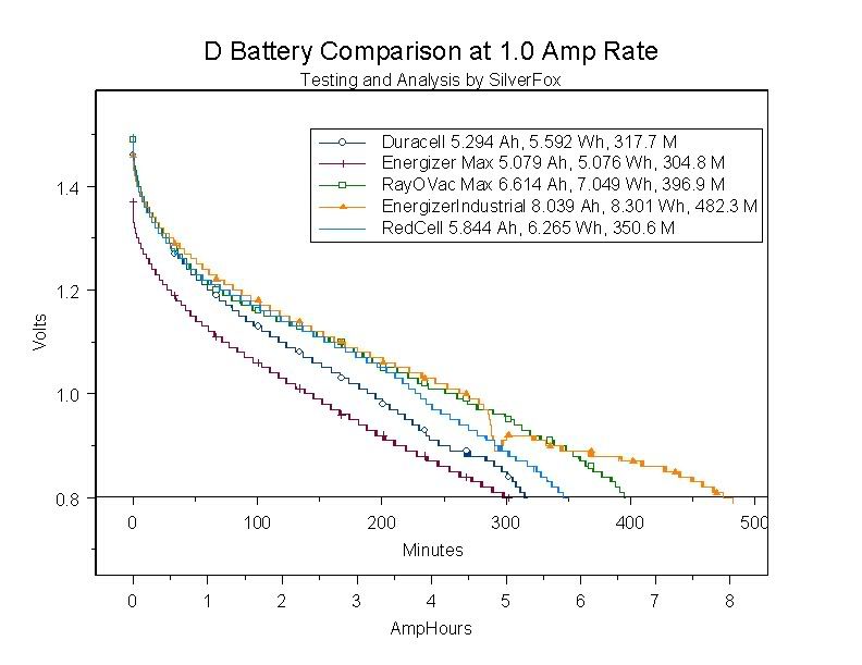
DComparison1A.jpg


I posted some thoughts here after taking a look at the AMC7135 datasheet. No one has responded to that post yet but it seems to me that if the thermal protection is activated the board would have to very well insulated. Has anyone themselves seen the thermal protection cut in, and how did they do it?

Edited: The first paragraph in the description indicates for a 3.7V LED you'd need at least 4.7V supply. That would rule out any alkalines except fresh ones.

A resistor sounds good. :laughing:
 
Last edited:

TorchBoy

Flashlight Enthusiast
Joined
Jan 15, 2007
Messages
4,486
Location
New Zealand
Oh, and BTW, I've found that the resistance in the M@g switch will limit the current to just less than 1a with 3D alkalines and a P4 emitter....at least that's what my meter is telling me.
Did you remember to take off the zero-reading of the meter (with the leads shorted together)?
 

TorchBoy

Flashlight Enthusiast
Joined
Jan 15, 2007
Messages
4,486
Location
New Zealand
Does anyone know if there is a noticeable runtime difference between a driver vs. a simple resistor setup?
I can remember doing calculations that showed for what I was doing at the time both were about 85% efficient. YMMV for this particular project. The brightness varying as the batteries flatten might be a bit much with alkalines and a resistor, but with NiMH I use a driver instead of a resistor more because I can than because I need to. (And because I like the idea of knowing the exact current it's running on.)
 

HarryN

Flashlight Enthusiast
Joined
Jan 22, 2004
Messages
3,976
Location
Pleasanton (Bay Area), CA, USA
As pointed out, 4 D alkalines are not that useful for 1 amp, but not bad for 500 - 700ma. 4 D NiCad / NiMH are pretty potent.

I am a Lux V fan, so if I were building this up, and wanted a lot of light, I would just put a simple boost circuit in there set for 500 - 700 ma and a Lux V - Photon Fanatic has them usually. You will be impressed with the output of even 500ma in a Lux V, esp, if you can get into the W or X bin versions. Don't go to 1 amp in the Lux V - it is usuallly counter productive in a mag body.

Yes, I know Cree and SS and K2s are the hot topics of the moment - I have tried those too - I am still a Lux V fan. Your nice large reflector will be fine with that big die set.
 

SafetyBob

Enlightened
Joined
Oct 20, 2007
Messages
766
Location
Yukon, Oklahoma
Have you considered a MicroPuck. You can use one Super High Output (500mA) by itself or maybe two regular MicroPucks (350mA) in parallel to get 700mA total for more brightness.

Check out www.theledlight.com. I have the 350mA at the house and have tested it with 2xCR123 lithium primaries and it really only lets through 350mA (OK, 349mA on my Fluke meter that hasn't been calibrated for 4 or 5 years). Amazing little electronic device. It will simplify things for you. Take a look.

Bob E.
 

wildstar87

Enlightened
Joined
Nov 12, 2007
Messages
369
1. Who told you that?

2. Why do you think that four alkaline D cells will give 6V for long enough to heat up that driver?


Edited: The first paragraph in the description indicates for a 3.7V LED you'd need at least 4.7V supply. That would rule out any alkalines except fresh ones.

A resistor sounds good. :laughing:

It was in another thread where I had asked for general advice on a 4D mod here: https://www.candlepowerforums.com/threads/180891

This is where it was indicated that 6V on that circuit would run hot, not being very knowledgable about the circuit, I guess I assumed that was from first hand experience.
 

wildstar87

Enlightened
Joined
Nov 12, 2007
Messages
369
Use this,
http://kaidomain.com///WEBUI/ProductDetail.aspx?TranID=2982

Then, I don't know if it will direct drive the LEDs once it gets below the 4.0V threshold (or if that is really accurate or just a ballpark for the current spec), but if it does not drive below 4V, put a parallel circuit to it with a schottky diode from the battery pack to the LEDs, this will allow running down at least 0.2V lower which is a lot with NiMH, a little less but still worth the few cents for a schottky diode with alkalines.

If you can accept ~ 950mA drive current (based on my measurements of same driver board @ 6V, the spec'd drive current is only true with closer to 5V input), you might try this instead,
http://www.dealextreme.com/details.dx/sku.3256

So far this driver looks good to me.

I'm driving a Cree on a 3D M@g host using 4 AA NiMh in a PVC sleeve. By soldering on a 1 ohm resistor in parllel to the existing resistor, the board pust out nearly 1000 ma. I'm receiving a lux meter this week, so I'll be running brightness/runtime tests on all my setups.


Good luck!


It looks like you two are indicating a similar function of using a parallel resistor? I'm not quite following how this would work, it sounds interesting. Can you explain further? Thanks!
 

TorchBoy

Flashlight Enthusiast
Joined
Jan 15, 2007
Messages
4,486
Location
New Zealand
The KENNAN board from KD seems like a great one. The efficiency of a buck supply and the dependability of a fixed current. It uses a small value resistor to determine what current it should output, 0.27 ohms in the case of the KD board. That happens to be at just the manufacturer-recommended maximum for the PT4105 control chip that board uses (there's a link to the datasheet somewhere in the forum). I wouldn't recommend changing the value of that resistor to anything smaller, such as by soldering another resister in parallel with it.

One drawback of that board is that it requires at least a volt of headroom. That would be about 4.4V, assuming your LED runs at about 3.4V at 750mA. That's perfect for 4 x NiMH cells but only 40-50% of the capacity of the alkaline D cells graphed above. J_C, can you please explain a little better how using a schottky diode can get around that problem?

AMC7135 has a minimum drop of 0.12V, so it could be used down to about 3.72V for a 1A output (and the 5 mode board will give you much more functionality).

Sorry, I don't have any experience with the 3.6V~9V 800mA board from DX, or what affect soldering other resistors in parallel with existing ones might have. My understanding is that the current it outputs varies a lot depending on input voltage. Is that right, J_C?
 

wildstar87

Enlightened
Joined
Nov 12, 2007
Messages
369
Well, I guess I will just try out the KD or DX board, it isn't that much to try so if it burns out, I'm not out much. Still not quite clear on the whole parallel resistor, what it's doing, and where it would be in the circuit, or outside the circuit...
 

El Conq

Newly Enlightened
Joined
Nov 27, 2007
Messages
9
Two resistors in parallel offer less resistance than a single resistor. Less resistance means higher current. Both resistors could connect at the same two points assuming there is enough space.
 

TorchBoy

Flashlight Enthusiast
Joined
Jan 15, 2007
Messages
4,486
Location
New Zealand
Two resistors in parallel offer less resistance than a single resistor. Less resistance means higher current. Both resistors could connect at the same two points assuming there is enough space.
Yes, but that doesn't mean it's a good idea. If the 0.27 ohm resistor on the Kennan board has a 1 ohm resistor soldered in parallel the total would be about 0.21 ohms. That would mean about 950 amps output, which would exceed the maximum spec (not just the max recommended) at anything less than about 8-8.5 volts input.
 

wildstar87

Enlightened
Joined
Nov 12, 2007
Messages
369
Well I wish I could say I was successful with the AMC7135 driver.. :(

I'm having some issues, maybe you guys that have been so kind so far can give me a clue..

First, yeah this board gets hot quickly with fresh Alkalines, and starts to flicker in probably less than 30 secs. Just to see if it would make any difference, I zip tied it to a heatsink, but it wasn't perfectly flat, and while it helped, it didn't help that much. So I doubt it would work if I potted it to the bottom of the LED heatsink.

However, that isn't the real problem IMO.. I'm am getting less output by my eyeball, than the Terralux TLE-6EX, with either a Cree Q5 or another SSC P4 U. This is one of the 16-mode drivers, and I cycle through all the modes to make sure I'm on high. I count 3 identical chips on the controller, so I don't think I have one of the lower driving ones.

I measured the load (I think correctly) between the LED and the driver, on the negative lead. If I remember correctly, it was somewhere around 500-600ma on the Cree.

I also measured at the tailcap with the SSC, and it seems to be running around 650ma.

I know Alkalines aren't the optimal, but I figured this setup would at least be AS bright, and expected to be brighter than the TLE-6EX. The light with the drop-in doesn't have fresh fresh batteries, they were new when I put them in, but I have been playing with it. These are fresh batteries I'm using on this mod.

I'm probably gonna go out and just get a resistor tomorrow and see how DD through a resistor makes any difference.

My first real mod isn't going as well as I had hoped.. :(
 

SafetyBob

Enlightened
Joined
Oct 20, 2007
Messages
766
Location
Yukon, Oklahoma
Hold on, I think I may have your solution. I just made a 9xAA Cree Q5 light using a Buckpuck. Look at the 3021-D-I-1000. www.theledlight.com has them for sale for $25.25. The part I don't know for sure is if you can just short the control and reference pins together (kind of a on/off thing) and run it like that or if you would have to stuff the external dimmer that comes with the optional wiring harness into the flashlight tube too. The main thing you are after is the internal ability to adjust output to 1000mA exactly as you wish. An email to them may straighten this out. You need to ask if you can run it with out a potentiometer because you just want constant, regulated 1000mA operation.

I did some testing with the cousin of this regulator (3021-D-E-1000) with 3 alkaline batteries and it was perfect. Once the batteries started loosing most of their power, the led started a noticable and relatively quick dim and stayed there for a long time. I wanted to do it with 4 (and I know it will work without a problem) but did not have the battery holders to do it with. I did use 4xAA (no problem) 6xAA (even less problems) and with 9xAA I got a really long lasting bright as you know what light that ran over 3 hours at 1000mA. I have 4 NiMH D sized cells coming and may try a 4 D light to see what happens with this Buckpuck thing. When testing with 4AA eneloops, they basically gave up the farm around 1.0VDC, so I liked that so it wouldn't potentially hurt the rechargeables. As I recall on the 4AA's runtime was around an hour and a half or so.....I would think that 4 D cells would contain much more total energy and give you at least 2 to 3 hours of good 1000mA runtime (I kinda looked at the charts too)

Just an idea!!

Bob E.
 
Last edited:
Top