Tweeking the "55W" Ballast to get an extra 18W @ Bulb

Morepower!

Enlightened
Joined
May 8, 2006
Messages
209
Location
Sydney, Australia
Tweeking a "55W" Kit Ballast to get an extra 18W-102W @ Bulb

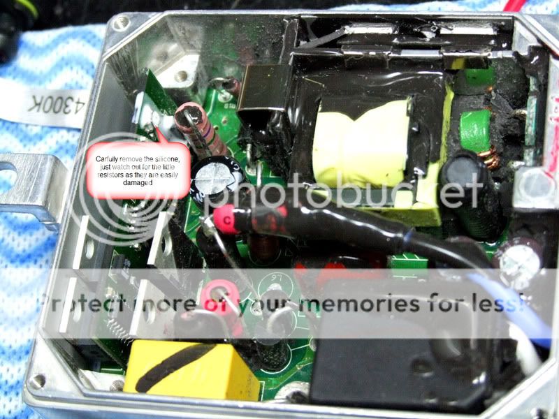
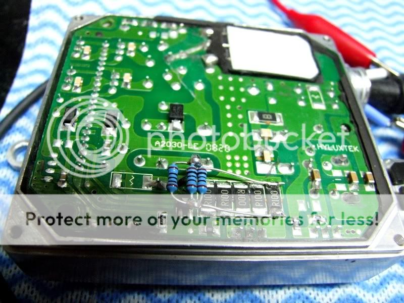
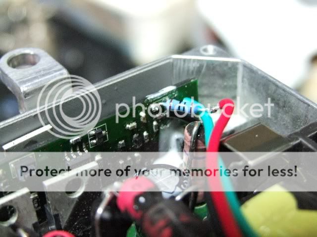
After trying many different things to get more power from these "55W" automotive kits I found a very simple Mod that will net an extra 8.8W(15.09W with 1.19K resistor) @ the bulb. I can't beleive the hours I've spent soldering resistors here and there, then testing and re-testing when all I had to do was turn up the pot !!!! I played with the pot a while ago, before setting up the test equipment, but couldn't see a difference and just dismissed it. Anyway 1/4 turn clockwise is all it takes, but don't go any further than that or you will start going backwards as the pot dosn't seem to have a definate stop.


New test results so far:
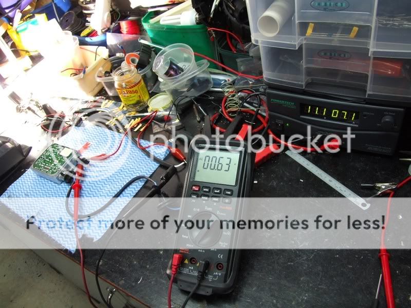
Just pot mod.

0.58A AC @ Bulb
88.1V AC @ Bulb
= 51.09W


Updated results:
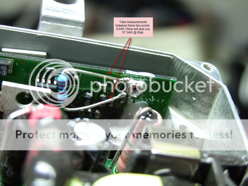
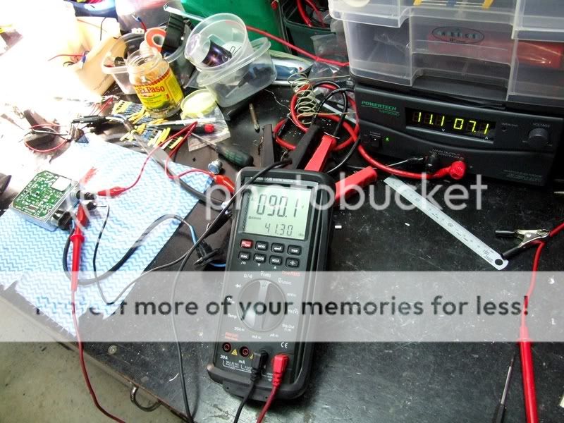
With 1.19K Ohm resistor

0.64A AC @ Bulb
89.6V AC @ Bulb
= 57.34W

Original test results HERE

.
 
Last edited:

Morepower!

Enlightened
Joined
May 8, 2006
Messages
209
Location
Sydney, Australia
Re: Tweeking the "55W" Ballast to get an extra 15W @ Bulb

Would there be significant life loss?? Ballast or bulb?

I really have no idea, anyone know if it would make much of a difference ?

On another note the pot resistance at it's lowest is 3.84K Ohms so I think i'll be able to get more out of it yet. If I can get 60W I think I should stop there ? I don't know how far I should try and push it.

EDIT: I have soldered a 1.19K Ohm resistor across the pot to give the lowest reading of 0.93K Ohms which is giving me 57.34W @ the bulb. I think i'm going to stop there as I don't know how much more the ballast will take. Besides i'm pretty happy with the results, I'm getting an extra 6,800Lux from the factory settings.
 
Last edited:

BVH

Flashaholic
Joined
Sep 25, 2004
Messages
7,023
Location
CentCalCoast
Re: Tweeking the "55W" Ballast to get an extra 15W @ Bulb

Good job, Morepower! Keep us updated on long-term results/life reduction good or bad.

Any thoughts as to whether the POT mod is the only difference between all the 35 watt kits and the 55 Watt kits on the market?
 
Last edited:

Flashanator

Flashlight Enthusiast
Joined
Jan 19, 2007
Messages
1,203
Location
The 11th Dimension
Re: Tweeking the "55W" Ballast to get an extra 15W @ Bulb

MorePower! thats amazing. Good work man:cool: Id be very happy with that wattage. And agree thats enough.

Lets hope they last long.:twothumbs
 

Patriot

Flashaholic
Joined
Feb 13, 2007
Messages
11,254
Location
Arizona
Re: Tweeking the "55W" Ballast to get an extra 15W @ Bulb

You did it! That's really good news, especially given the fact that it's not a difficult mod.

Thanks Morepower. :)
 
Last edited:

Morepower!

Enlightened
Joined
May 8, 2006
Messages
209
Location
Sydney, Australia
Re: Tweeking the "55W" Ballast to get an extra 15W @ Bulb

Hey, no problem guys. I'm always more than happy to share any results I get, both good and bad. That's what I like about Forums, just about anything is possible.

Now for the "how to". The resistor used is a 0.5W, 1.19K Ohm(measured on a meter as I'm too lazy to work out the colour bands). Soldering the resistor across the pot is a little difficult due to it's position and the small size of the soldering pads. I found the best way was to pre-solder the legs of the resistor, leaving a tiny blob right at the tip, then doing the same with the pot pads. You will need a fine tipped soldering iron and a steady hand, hold the leg on the pad and apply just enough heat to melt them together. Try to set it in the right position from the beginning as bending the legs later on can result in ripping the pad off the PCB. Once that is done turn the pot clockwise until you get a reading of 0.93K Ohms and your done, 57W @ the bulb. Also note that the ballast now pulls an extra 2 Amps @ 11.1V on the input. See pics below.

As to whether this mod. will shorten the life of the ballast or bulb is yet undetermined, so perform it at your own risk I guess. It is my opinion that doing just the pot mod. alone should be fine if being used in a torch as the ballast dosn't have to deal with the added heat it would normally be subjected to from being situated in the engine bay of a car.

I've decided to keep pushing my poor old, beat up ballast to 65W, if it will do it, then do some run time vs heat tests. I can't believe it is still going, I've reduced resistance at many points throughout the circuitry, repaired broken tracks, gouged tracks, cracked a ceramic resistor and tore off a solder pad and repaired it !! My only concern is I have removed all the thermal rubber compound, at least I'm assuming it is to help with heat dissipation, from the ballast in order to see what makes it tick. BTW does anyone know what that stuff is ? And better still where I might be able to purchase some from ? I guess if it fails attempting 65W I'll chalk it up to a casualty of bettering the hobby.

The Pot

Pot1.jpg


The resistor Mod

PotMod119KResistor1.jpg


The test results

PotModMeasurementsVolts.jpg


PotModMeasurementsAmps.jpg


This Mod managed to double the start up current only :eek:

ResistorBank.jpg
 
Last edited:

Morepower!

Enlightened
Joined
May 8, 2006
Messages
209
Location
Sydney, Australia
Re: Tweeking the "55W" Ballast to get an extra 15W @ Bulb

I just found the ballast's limit. I,ve totally rung it's neck and I can't get anymore power out of it, I doubt even Scotty could get more out of it.

With 243 Ohms across the pot I get the following:

90.0V AC @ Bulb
0.65A AC @ Bulb
= 58.5W
Input current is 7.4A @ 11.1V DC
Making an extra 6,900Lux above factory settings.

I will do some runtime and temp. tests to see how it's now going to stand up to the punishment.
 

Flashanator

Flashlight Enthusiast
Joined
Jan 19, 2007
Messages
1,203
Location
The 11th Dimension
Re: Tweeking the "55W" Ballast to get an extra 15W @ Bulb

:devil:

I pray for long lasting performance...

So anyone care to take a bulb lumen guess at 58w output?

Doesn't the lumen/watt efficiency go thru the roof as you overdrive the bulb?

would it be near or over 6000lumens?


I really hope this setup lasts. :)
 

Morepower!

Enlightened
Joined
May 8, 2006
Messages
209
Location
Sydney, Australia
Re: Tweeking the "55W" Ballast to get an extra 15W @ Bulb

Any thoughts as to whether the POT mod is the only difference between all the 35 watt kits and the 55 Watt kits on the market?

I was wondering the exact same thing, and knowing what I know now I'm thinking they might be the same ballast. Do you think the 35W and 55W bulbs are the same though ? If you think they are I'll buy a 35W kit and test it, but if not I don't really want to waste the money on the ballasts and not have the right size bulbs to go with them.

I've just finished doing some runtime/temp. tests at the max ouput level.

@58.5W

Start temp. 20⁰C

10 mins. 50⁰C
15 mins. 59⁰C
25 mins. 74⁰C
30 mins. 78⁰C
40 mins. 103⁰C

NOTE: The thermocouple was situated on the outer case at the point where the power transistors(or FETS ?) are mounted. After some searching I found a wide range of operating temps for transistors, from -65 ⁰C to +200 ⁰C. I don't really know what a "safe" operating temp. would be for this ballast but I am going to heatsink it when I get a chance.
 

scott.cr

Flashlight Enthusiast
Joined
Jan 10, 2006
Messages
1,470
Location
Los Angeles, Calif.
Re: Tweeking the "55W" Ballast to get an extra 15W @ Bulb

I found a wide range of operating temps for transistors, from -65 ⁰C to +200 ⁰C. I don't really know what a "safe" operating temp. would be for this ballast but I am going to heatsink it when I get a chance.

They are probably FETs. I work for a company that makes RF amplifiers (which of course means we use plenty of FETs) and we consider the upper continuous safety limit to be 70-75 °C. Sometimes we go to 85 °C on customer request.

From the pics, it looks like you can easily improve heatsinking on the FETs near the chassis wall by using a THIN layer of thermal paste and screwing the tabs to the chassis. For the FETs not immediately next to the chassis wall you will have to be more creative in your heatsinking.

If the FETs are bipolar these are not the most rugged technology so you should be careful not to overheat them. It doesn't take much to "defeat" a bipolar transistor.
 

Morepower!

Enlightened
Joined
May 8, 2006
Messages
209
Location
Sydney, Australia
Re: Tweeking the "55W" Ballast to get an extra 15W @ Bulb

They are probably FETs. I work for a company that makes RF amplifiers (which of course means we use plenty of FETs) and we consider the upper continuous safety limit to be 70-75 °C. Sometimes we go to 85 °C on customer request.

From the pics, it looks like you can easily improve heatsinking on the FETs near the chassis wall by using a THIN layer of thermal paste and screwing the tabs to the chassis. For the FETs not immediately next to the chassis wall you will have to be more creative in your heatsinking.

If the FETs are bipolar these are not the most rugged technology so you should be careful not to overheat them. It doesn't take much to "defeat" a bipolar transistor.

Thanks for your input scott.cr. I've "defeated" many a transistor in my time :naughty:. The FETS that are putting out the most heat are the ones pointed out in the pic below. Whilst they are not screwed to the chassis they are covered in the black rubber compound and do have that silicone impregnated rubber mat behind them. Do you think that is good enough ? I hope so because screwing them to the chassis would be a real pain. I'll probe the rest of the FETS just to make sure they are within the safe heat limits.


FETS.jpg


I've just completed some runtime vs heat tests on a STD ballast and the pot mod only.

STD ballast(42.29W)

Starting Temp. 20˚C

10 mins. 34˚C
15 mins. 39˚C
40 mins. 54˚C
50 mins. 58˚C


Pot mod.(49.28W)

Starting Temp. 25˚C

10 mins. 43˚C
15 mins. 49˚C
20 mins. 54˚C
30 mins. 62˚C
40 mins. 68˚C
50 mins. 72˚C
1 hour 75˚C
1.5 hours79˚C
2 hours 81˚C


NOTE: All measurements were performed in "free air". Anyway you guys can draw your own conclusions on the info supplied as i'm just about done with all the boring testing(besides the wife is getting on my back) and am going to TEC cool my ballast and build it into a host so I can start blasting things with the new found extra power :devil:. If I have any failures or find out anything of significance i'll post it. Also if any of you guys give it a go please let us know how it went, good or bad.

I'm thinking maybe this light ?

NewLight.jpg
 
Last edited:

liveforphysics

Enlightened
Joined
Dec 4, 2006
Messages
343
Re: Tweeking the "55W" Ballast to get an extra 15W @ Bulb

[FONT='Verdana','sans-serif']Outstanding work! Very good to know that the lower current sensing resistors only change the start-up current levels.[/FONT]

[FONT='Verdana','sans-serif']My job involves finding cooling solutions for servers. My experience with TEC cooling for devices with this low of output has been very poor. Remember, your device is only requiring around 10w of energy to be removed. Sticking even a 10w TEC in the setup will mean a doubling the thermal energy generated by the device. Yes, it will be a bit higher grade energy (delta-T), so a sink can function a bit more efficiently, but you are also asking it to double or more than double the thermal load.[/FONT]

[FONT='Verdana','sans-serif']Use acetone to prep the surface of the case, and thermal epoxy a thin computer heat sink onto the side of the case. Unless you are trying to operate the ballast in some very high temperature environment, this will be more than enough to reach thermal equilibrium at a safe temperature for the ballast.[/FONT]

[FONT='Verdana','sans-serif']Great work! I'm going to perform this modification on the ballasts I use on my cars and motorcycles. I think I will run leads from that point out of the ballast, so I can have external variable control of the current through the bulb. Perhaps connecting to a DPDT relay with varied resistances to permit a high/low beam current changing function.[/FONT]

[FONT='Verdana','sans-serif']Best Wishes,[/FONT]
[FONT='Verdana','sans-serif']-Luke[/FONT]
 

liveforphysics

Enlightened
Joined
Dec 4, 2006
Messages
343
Re: Tweeking the "55W" Ballast to get an extra 15W @ Bulb

Outstanding work! Very good to know that the lower current sensing resistors only change the start-up current levels.

My job involves finding cooling solutions for servers. My experience with TEC cooling for devices with this low of output has been very poor. Remember, your device is only requiring around 10w of energy to be removed. Sticking even a 10w TEC in the setup will mean a doubling the thermal energy generated by the device. Yes, it will be a bit higher grade energy (delta-T), so a sink can function a bit more efficiently, but you are also asking it to double or more than double the thermal load.

Use acetone to prep the surface of the case, and thermal epoxy a thin computer heat sink onto the side of the case. Unless you are trying to operate the ballast in some very high temperature environment, this will be more than enough to reach thermal equilibrium at a safe temperature for the ballast.

Great work! I'm going to perform this modification on the ballasts I use on my cars and motorcycles. I think I will run leads from that point out of the ballast, so I can have external variable control of the current through the bulb. Perhaps connecting to a DPDT relay with varied resistances to permit a high/low beam current changing function.

Best Wishes,
-Luke
 
Last edited:

Morepower!

Enlightened
Joined
May 8, 2006
Messages
209
Location
Sydney, Australia
Re: Tweeking the "55W" Ballast to get an extra 15W @ Bulb

Outstanding work! Very good to know that the lower current sensing resistors only change the start-up current levels.

My job involves finding cooling solutions for servers. My experience with TEC cooling for devices with this low of output has been very poor. Remember, your device is only requiring around 10w of energy to be removed. Sticking even a 10w TEC in the setup will mean a doubling the thermal energy generated by the device. Yes, it will be a bit higher grade energy (delta-T), so a sink can function a bit more efficiently, but you are also asking it to double or more than double the thermal load.

Use acetone to prep the surface of the case, and thermal epoxy a thin computer heat sink onto the side of the case. Unless you are trying to operate the ballast in some very high temperature environment, this will be more than enough to reach thermal equilibrium at a safe temperature for the ballast.

Great work! I'm going to perform this modification on the ballasts I use on my cars and motorcycles. I think I will run leads from that point out of the ballast, so I can have external variable control of the current through the bulb. Perhaps connecting to a DPDT relay with varied resistances to permit a high/low beam current changing function.

Best Wishes,
-Luke

Hey Luke, thanks for the info on the TEC's. I've played around with them a little in the past, but am no expert. They most certainly produce alot of heat and sinking is a must. The one I mounted met with an unfortunate accident, but sounds like it wasn't going to do the job I needed it to. On your recomendations I will just use a heatsink, which I already had on order anyway. I have a white silicone compound that sets like silicone sealant, that is supposed to have good thermal properties, which i've used on some LED's. It's not an epoxy that i'm aware of, would it be good enough ?

Speaking of external pots, I just finished the following mod.

ExternalPot.jpg


ExternalPotWiring.jpg


I was looking around on hidworld.com and got the idea for the external pot from there, there are some very interesting mods being done over there. Though most are being done with the OEM ballasts.

I removed the original pot, the resistor is 0.5W, 179 Ohms and Pot is 5k. At the highest resistance(5K Ohms) the ballast is doing 49.45W @ bulb, at the lowest(179 Ohms) I'm getting 60.86W(got my 60W !!!!:D). Good idea switching between resitances for high/low. Before I stick the ballast into a torch if you want any particular wattage levels @ bulb I will let you know what figures to use for resistance if you like. You might be able to work out it out from the figures already here but I don't know if it works out to be linear. Otherwise let me know ASAP as I'm hanging to fire it up in my last mod.

EDIT: I wouldn't attempt this mod. unless you are prepared to possibly destroy your ballast(s). I will be using mine on a regular basis from now on to see how it stands up to the punishment and will report any failures immediately here. But so far so good. Does anyone have any thoughts on what components would be most likely to fail, if any ?


.
 
Last edited:

Flashanator

Flashlight Enthusiast
Joined
Jan 19, 2007
Messages
1,203
Location
The 11th Dimension
Your crazy MorePower!!!!! :D 60w:whistle:

Would Love to know how many lumens.:eek:

I hope this 60w mod will be good for a show & tell light, not heavy use.

Would I need heatsink for running at 20mins runs in vector twin? Theres not much room in VT.
 

Morepower!

Enlightened
Joined
May 8, 2006
Messages
209
Location
Sydney, Australia
I need some advice/thoughts on a couple of things.

1.) Can anyone see a problem with the way I hooked up the external pot ?

The reason I ask is since intalling the pot the bulb won't ignite unless the pot is turned up to full power, but works perfectly when It is and I can turn it up and down without a problem. The other thing, which is actually a good thing, is that at the lowest setting(49.45W) it is producing ALOT less heat now, 59°C @ 60 mins. compared to 75°C @ 60 mins.(49.28W) from before the mod. This has me completely baffled and I'm wondering if I've done something wrong ?

2.) I'm assuming the pot is setting the "on" bias current to the FETS, if this is the case do you think itwould be a good idea to remove the 179 Ohm resistor and let the pot supply all the current available ?

EDIT: Flash I'd say it would be ok, but in reality your guess would be as good as mine at this stage.
 
Last edited:

Morepower!

Enlightened
Joined
May 8, 2006
Messages
209
Location
Sydney, Australia
UPDATE: I did do something wrong when installing the external pot. I used a 1/2Watt resistor which was big enough to handle the "run" current but it seems not big enough to handle the "start up" surge. I removed the resistor all together and am running full power to the FETS. It now starts up at all power levels without a problem. It also netted an extra 2W, giving me a total output of 62.24W.

My concern is not for the ballast anymore. Looking at the start up figures they put out ~140W every time they are turned on. Granted that this is only for a very short time but it shows that they are at least built to deliver alot more power than I am pushing them too. I'm hoping that by sinking away the extra heat generated I might be able to get some decent lifetime out of it at full power. If a heatsink is not practical then maybe sticking to an on/off cycle that would suit.

My main concern now is for the "55W" bulbs supplied. I took a close look at the bulb I have been using for testing and it appears at some point the pressure has been so high that the gas has pushed it's way past the glass seal around the bottom electrode :eek: I could try and take a pic of this if anyone is interested. Since discovering this I have put some aluminium plate as a shield between myself and the bulb. So now I am thinking I need to go with a DL-50 fatboy(if I can get them), or maybe a GE 35/50W bulb ? It's starting to make sense to me why these ballasts are throttled back. I don't know what you guys think.
 
Last edited:

Flashanator

Flashlight Enthusiast
Joined
Jan 19, 2007
Messages
1,203
Location
The 11th Dimension
if the bulbs explode, wonder if the glass or reflector will be damaged in a light?

I might start stocking up on these H7 bulbs then. For my mod the fatboys wouldn't fit, too long. its a tight fit:(
 
Top