The Ultimate MC-E Mounting Solution?

VanIsleDSM

Enlightened
Joined
Oct 16, 2007
Messages
649
Location
Victoria BC, Canada.
I'm very excited for the new MC-E coming out. I've already designed and built a driver for the MC-E, and I'm almost finishing turning a host for it on the lathe.

Since the 4 die construction will be much more thermally dense than 4 separate LED packages, I want to be able to eek out every little bit of heat I can, not only for efficiency and longevity, but to hopefully make certain that I can safely run these up to 1000mA per die.

So what I've done is this:

HPIM1427.jpg


HPIM1428.jpg


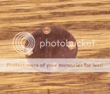
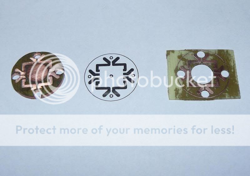
It may not look too special, but there is actually no dielectric layer involved for the thermal path. I machined down a piece of copper to an 18mm diameter, then I took a little over 1/64" of material off the face, but leaving a round nub in the middle, a little bigger than the thermal pad for the MC-E. I etched out the mounting design with the pads for the MC-E onto some 1/64" FR-4 board, drilled a hole in the middle of the FR-4 for the nub on the copper, laminated the FR-4 onto the copper, and then lapped the whole thing flat on both sides to 2000 grit on a piece of glass.

I sanded a little much, and slightly took off a couple of the wire mounting pads, but not so bad for a first try.. and it'll still work just fine.

This time I just made a thin mounting board, however for many projects I'll just be using the same process but I'll make the copper piece the whole heatsink.

The thin boards could be reflow soldered, while the larger heatsinks would hold too much heat to be able to control the temp properly during reflow I think. But no matter, I don't plan to solder, just A.S. epoxy the heat pad under high pressure, and hand solder the pins.

I may try reflowing some in the future, but there's almost no difference between a very thin layer of A.S. epoxy on 2000grit glass lapped copper, and between actual solder.

What do you guys think? what else could I do to improve the design?


p.s. Sorry for junk pics.. I'll get some with my other camera tomorrow.
 
Last edited:

ICUDoc

Enlightened
Joined
Aug 20, 2004
Messages
907
Location
Sydney, Australia
Very clever way to make the board. Love the solid copper design, and a big fat flat bottom to heatsink further. Looks nice.
 

Illum

Flashaholic
Joined
Apr 29, 2006
Messages
13,053
Location
Central Florida, USA
Considering the dize of the LED, thats an interesting concept to mounting it, but how will you keep its 8 individual legs from contacting the board? or are you planning to try the 4 bins on each side together?:candle:


I've always been curious as to how drivers are designed, will there be documentation on the build? what about schematics? could that be posted after everything is done? :thanks:
 

TexLite

Enlightened
Joined
Jun 30, 2007
Messages
595
Location
Texas
Looks great to me,nice job.

Hows the driver coming?

On a side note,diggin around You-Tube the other day,I came across some interesting vids by none other than....VanIsleDSM,sequencer taillights and such.Very impressive work!You should link some of those in your sig.

-Michael
 

VanIsleDSM

Enlightened
Joined
Oct 16, 2007
Messages
649
Location
Victoria BC, Canada.
Considering the dize of the LED, thats an interesting concept to mounting it, but how will you keep its 8 individual legs from contacting the board? or are you planning to try the 4 bins on each side together?:candle:


I've always been curious as to how drivers are designed, will there be documentation on the build? what about schematics? could that be posted after everything is done? :thanks:

I'll have to take some better pics. There's a PCB laminated onto the copper (just not over the heatpad). Each die is individually addressable. The driver is already finished, for the most part.. It's all completely working, I'm just going to add a micro controller to give it different output levels. It's a buck driver, takes 6 Li-Ion cells, as efficient as I could possibly make it. Drives the 4 dies in series, here's some efficiency testing, not extremely accurate, I wasn't using sense resistors to measure current, just DMMs.. I'll do a more accurate job when I have the final drive levels all figured out and such.

efficiency.jpg


Looks great to me,nice job.

Hows the driver coming?

On a side note,diggin around You-Tube the other day,I came across some interesting vids by none other than....VanIsleDSM,sequencer taillights and such.Very impressive work!You should link some of those in your sig.

-Michael

Thanks Tex. Still haven't finished my taillight project.. kinda been backburnered lately. Thuoght I do have the whole big micro controller board made up to controll the sequencing singals and PWM for marker lights and brake lights... but I've got a bit of troubleshooting to do there, and then a bit more construction on the actual taillights themselves.
 

VanIsleDSM

Enlightened
Joined
Oct 16, 2007
Messages
649
Location
Victoria BC, Canada.
Alright.. took another pic. This one should show what's going on properly.

The PCB has the hole in the middle, so the solid copper core from underneath comes right up through the PCB board to contact the thermal pad of the MC-E with nothing in the way.

Each pin can be individually addressed for any series/parallel configuration, and the wires brought down through the outer holes.

P1010751.jpg
 

Oznog

Enlightened
Joined
Dec 2, 2006
Messages
595
Seems like it'd be a shame to only use thermal epoxy when you could probably solder it. That'd be the weakest link in the thermal path for sure.

Copper might take an excessive amount of time to heat up on a toaster oven- but not on a hotplate. Also just putting it over a heatgun is nice. That shields the device from the hottest of the air and but it can heat up real fast or slow depending on distance and gun temp.
 

VanIsleDSM

Enlightened
Joined
Oct 16, 2007
Messages
649
Location
Victoria BC, Canada.
I used a press with a jig that I made to laminate the PCB board with JB weld. Automotive epoxy that's supposed to be able to handle 315C for 10min or less, and 260C indefinitely. So it should be fine for SMT, though it'll probably off-gas somewhat I imagine.

I use the press to epoxy XR-Es to bare copper under high pressure with a jig. I plan to do the same with the MC-Es. I think with this method, lapping both surfaces on glass with 2000grit (I've heard in the PC world that going as far as polishing will actually have a negative effect on heat transfer) I'll get such a thin bonding layer of epoxy that using solder would only be negligibly better. I can even solder the MC-E down while it's in the press.

When I make whole 1 piece mount/heatsinks that are half an inch long with threads and all.. I dunno how that'd react to reflow, the cooling anyway.. it'd wanna stay hot for a while, you'd have to figure something out to cool all that thermal mass at a controlled rate.

Though.. like I said, I do plan to give the reflowing a shot.. I have a hotplate I've used before with just a thermometer, but not for delicate things like LEDs. I don't have a controller yet.. it's on the to do list. Still haven't decided whether I want to take the time to build one, or just buy one.

I'll look around to see how thin of a layer of A.S. is possible under high pressure and try and work out some numbers later.. back to the garage now though, have to finish building some battery chargers for CPFers.
 
Last edited:

VanIsleDSM

Enlightened
Joined
Oct 16, 2007
Messages
649
Location
Victoria BC, Canada.
Thanks saabluster. I'm not sure yet whether there will be enough room to possibly run the links between dies on top of the board? and then you could use 2 holes for routing wires, and 2 holes for mounting. I suppose it will depend on the optic you use. I may be able to squeeze some mounting holes into the current design though.
 

frenzee

Enlightened
Joined
Sep 4, 2006
Messages
216
Excellent post, VanIsleDSM. I suggested this same exact process about a year ago to another member, but with a couple of slight variations:

First, I'd highly recommend you solder it. It will make a HUGE difference in heat transfer. The numbers for AS may look good on paper, but boundary layer imperfections between copper and e.g. AS is the Achilles's heel of any epoxy.

Secondly, instead of crafting a nub in the middle of the heat sink, as you put it, why not just sand it flat and then cut a round copper disk the same size as the hole in your FR4 and the same thickness as well. Epoxy the edges of the disk to the FR4, jut enough for it to stay in place, put a dab of solder paste on the heat sink, both sides of the disk in the FR4 and the slug of your emitter, sandwitch all the three pirces together, put a small weigth on top to hold everything together and do the toaster oven thing. Also put a dab of toothpaste on the emitter's dome to protect again thermal shock. You can wipe it off later with IPA.

I think this might be an easier approach, but I don't know. I have not actually tried it yet. Be sure to post pics when it's done.
 

VanIsleDSM

Enlightened
Joined
Oct 16, 2007
Messages
649
Location
Victoria BC, Canada.
Thanks Frenzee. I've thought about doing something like this for the XR-E, but I never bothered because I would have had to reflow it. With the MC-E it'll be much easier to hand solder.

I'm not convinced solder is all that much better. From my observations the differences are pretty minimal.. but like you pointed out, you have to make sure you do an excellent job of epoxying down the emitter, good prep, lapping and clamping. With a layer 0.001" thick you get a thermal resistance of 2.9W/C in a 1mm² area. That means 0.08C/W from the pad to the sink with an XR-E, and I'm fairly certain with my clamping methods that I achieve a layer less than 0.001 thick, that's quite a bit. Now compare that to the size of the die, and the thermal resistance of the LED between die and pad, 8C/W for the XR-E... with this figure far outweighing the thermal resistance between the pad and sink, it's really not really going to make any difference. 0.08C/W is a thermal 16 lane freeway compared to the gravel mountain road of 8C/W.
 

billw

Enlightened
Joined
Nov 2, 2002
Messages
295
Location
SF Bay Area
I like the idea a lot on a concept level. It should work pretty well with lesser LEDs, easier-to-machine aluminum, and thicker PCB material. In fact, I can visualize a sort of jig to mount a standard heatsink on a lathe or mill and machine away an appropriate thickness everywhere that you don't want a mounting "stud" for the LED body itself... Hmm.
 

frenzee

Enlightened
Joined
Sep 4, 2006
Messages
216
I have a high level of confidence that this approach will work. I did a prototype using 1/64" single-sided fiberglass PCB a while back, but I had way too many emitters on a single board and they were only 2mm in diameter, so it was getting very difficult to keep all the slugs/disk in place during the reflow. But if you have just one or two emitters, there is no reason why it shouldn't work. After all, this is almost the same concept that Lumileds used on the Lux Stars, except they used a ceramic-based epoxy to attach the slug to the aluminum disk and simply bent the leads flush against the fibergalss PCB. That approach 0bvously won't work with Rebels.

Aluminum would be much easier and cheaper to machine, but you can't solder aluminum, so that would be a big disadvantage IMO. I wish there was an easy way to silver or copper plate aluminum, but AFAIK, there isn't one. You have to Nickel plate, etc. which is to impractical for me.


Oznog

Enlightened
Joined
Dec 2, 2006
Messages
595
I'm not convinced solder is all that much better. From my observations the differences are pretty minimal.. but like you pointed out, you have to make sure you do an excellent job of epoxying down the emitter, good prep, lapping and clamping. With a layer 0.001" thick you get a thermal resistance of 2.9W/C in a 1mm² area. That means 0.08C/W from the pad to the sink with an XR-E, and I'm fairly certain with my clamping methods that I achieve a layer less than 0.001 thick, that's quite a bit. Now compare that to the size of the die, and the thermal resistance of the LED between die and pad, 8C/W for the XR-E... with this figure far outweighing the thermal resistance between the pad and sink, it's really not really going to make any difference. 0.08C/W is a thermal 16 lane freeway compared to the gravel mountain road of 8C/W.

Well, I've never been able to get an estimate of AS thickness that I can swear by, this is what AS says:

[FONT=Arial, Helvetica][SIZE=-1]Stock processors and/or heatsinks with normal surface irregularities or that are slightly concave or convex will require a layer 0.004" to 0.008 thick to fill the resultant gaps. (Equal to the thickness of 1 to 2 sheets of standard weight paper.) Properly lapped processors and heatsinks will require a thinner layer.[/SIZE][/FONT]
And 7.5W/m*K.
The MC-E only has a 2.6x5.4mm pad, 14.04 sq mm. Hopefully it would fall under the "thinner" estimate, but then clamping these devices might be less effective than anticipated since the lens can't take a lot of compression. At 0.004", I get 0.964C/W for the layer.

Hey our calcs don't agree. On a 0.001" that you estimated, I get 3.387C/W per sq mm but not 0.08C/W per sq mm!

For 1 sq mm:
1 sq mm=1e-6 sq m
0.001"=25.4e-6 m
conductivity=7.5W/(m*K)=0.1333333 m*C/W

( 0.133333 m*C/W )*25.4e-3 m / 1e-6 m^2= 3.386 C/W

? What went into your calc? Did I screw something up on mine?

Of course if it's actually 3.386C/W per sq mm then with a 14.04 mm thermal pad we're talking 0.24C/W which is indeed negligible anyways.
 

frenzee

Enlightened
Joined
Sep 4, 2006
Messages
216
I get .24C/W, per the following, assuming running the MC-E at 3W, but this is just theory IMO. The theoretical thermal resistance is negligible compared to the boundary layer thermal resistance (article):

q = k A dT / s (link)

q =
heat transferred per unit time (W) = 3 W
k = thermal conductivity of the material (W/m.K) = 7.5 (link)
A = heat transfer area (m2) = 14.04/1000,000 = 1.4E-5
dT = Temperature difference across the material (K or oC) = to solve for
s = material thickness (m) = .001" = .0000254

so dT = 7.2E-01 at 3W or .241 C/W
 
Top