PCC
Flashlight Enthusiast
I've noticed that no one has reported on modifying a Cateye HL-EL510, yet. There are modified HL-EL500s and HL-EL530s but no HL-EL510s, until now.
In a little over a year of commuting by bike I've made a few attempts at bike head lights both to be seen and to see. Everything I've bought so far, except the NiteRider Minewt Mini-USB, has been a disappointment and that includes the HL-EL510. It puts out a decent amount of light for a compact unit but it doesn't put out enough light to see where you are going. Pointing the hotspot about 25 feet out in front of the bike on a completely dark street you can barely make out a lighter spot compared to the surrounding darkness.
Recently, I bought a few Seoul SSC P4 U-bin LED emitters recently from DX and they arrived today. Since the HL-EL510 was a disappointment and it was so easy to take apart and mod I just could not wait so here we go...
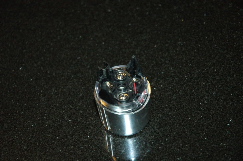
Here's the head as it sits, waiting to be taken apart. You carefully pull on the legs, wiggling as you go, being careful not to get the black plastic piece cockeyed in the reflector housing, preventing it from coming out. If you manage to pull the assembly with the legs out then you have to carefully pry the remaining black plastic piece out carefully. Don't pull too hard or you could pull those wires out.
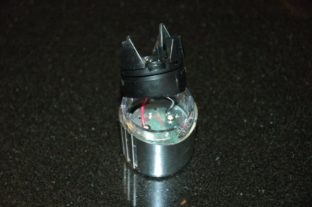
Here's the black plastic assembly removed from the reflector assembly. The two wires go to the heatsink which is attached to the reflector assembly by two small screws. Remove the two screws and the heatsink comes out, too.
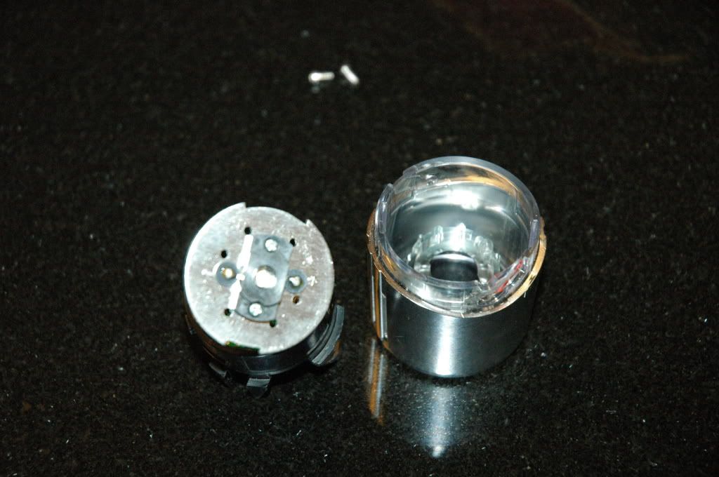
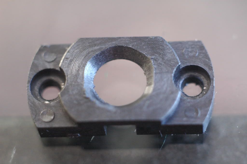
Here's the heatsink removed from the reflector assembly. Two more small screws (these are shorter than the first two you removed so don't mix them up) and the plastic shroud comes out. Desolder the LED and you're in ready to replace it.
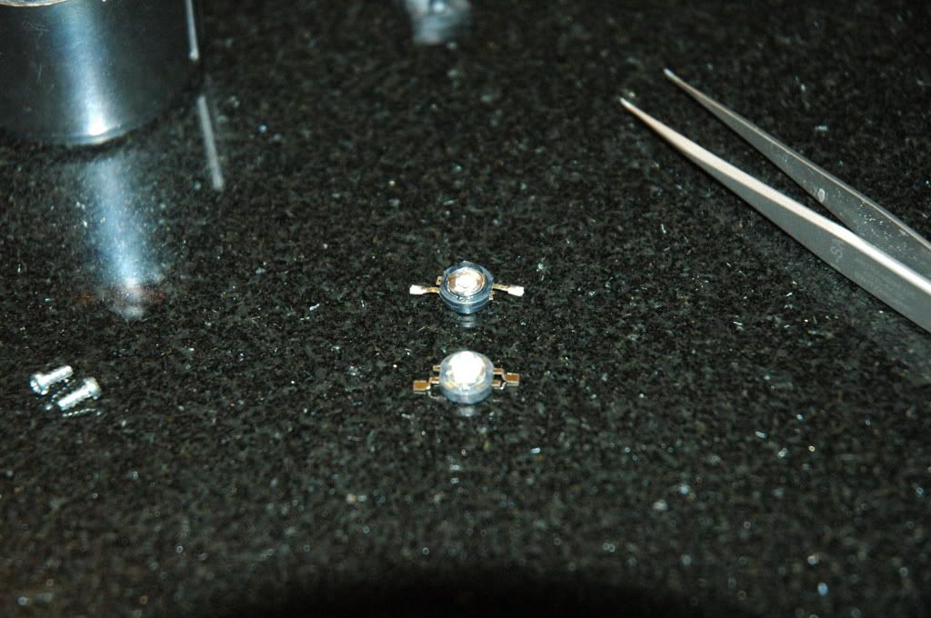
In the foreground is the new SSC P4 LED waiting to be installed. In the background is the old Luxeon LED. I had to flatten out the contacts before soldering. After removing the Luxeon LED I noticed that there was no thermal compound nor any type of epoxy in place to assist the conduction of heat to the heatsink from the back of the LED. I made sure to dab some on there before soldering the P4 LED in place.
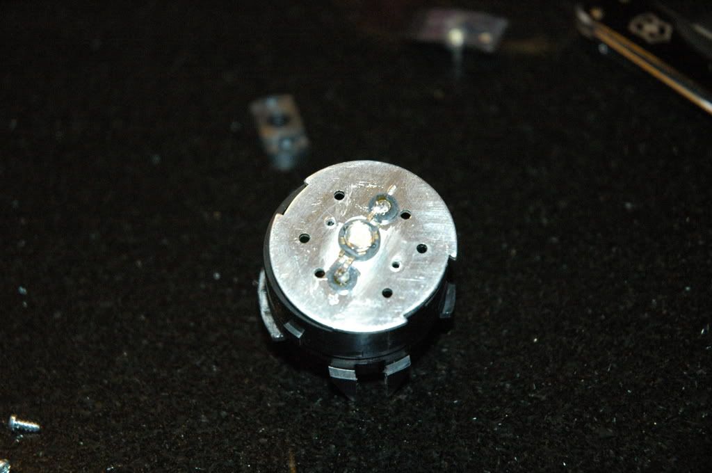
Here's the SSC P4 LED soldered in place waiting for the reinstallation of the shroud. In hindsight, I should have installed the shroud first to hold the LED in place to make soldering the leads easier.
Reassembly is the reverse of disassembly but the parts are keyed to go back together in a certain orientation relative to each other. The heatsink is keyed to attach to the black plastic piece that holds the circuit board in one orientation and the black plastic part with the legs have to go in only one way relative to this, too. The black plastic assembly is keyed to go into the reflector housing in only one way, too. Before assembling everything to the reflector housing I put the heatsink in the black plastic housing assembly then lined up the keys with the slots in the reflector then lined up the tail piece with the legs so that the red line on the one leg lines up with the red line on the reflector assembly then snapped that piece into the housing assembly with the circuit board. I then lined up the heatsink with the reflector assembly and reinstalled that first. The rest just falls into place.
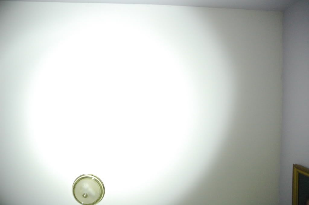
And now, the beamshots against my ceiling. All pictures, except for the last two, were taken at 18 mm, f3.5, 1/4 second, and ISO 800. The camera was tripod mounted low to the ground and the lights were placed on the ground about a foot over from the camera to avoid having the shadow of the camera in the picture.

Here's the baseline shot showing the relative light level in the room. Dark, eh?
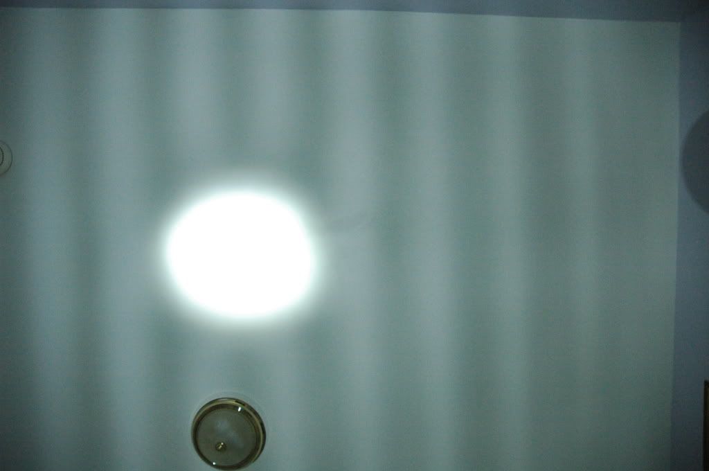
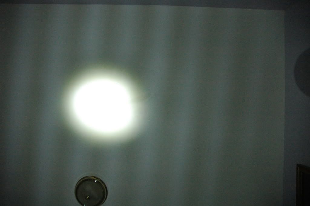
Here's the unmodified HL-EL510 headlight beamshot. Those straitions are from the lens in an attempt to widen the beam on the road.
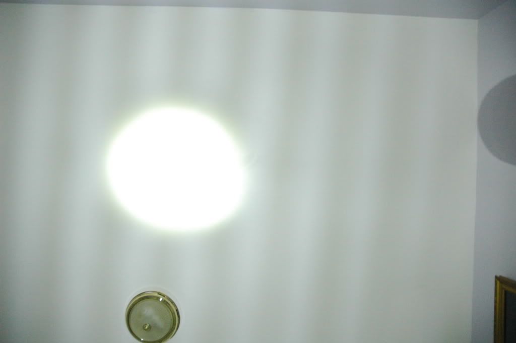
Here's the modified HL-EL510. The hotspot is larger and brighter. The spill is brighter, too.
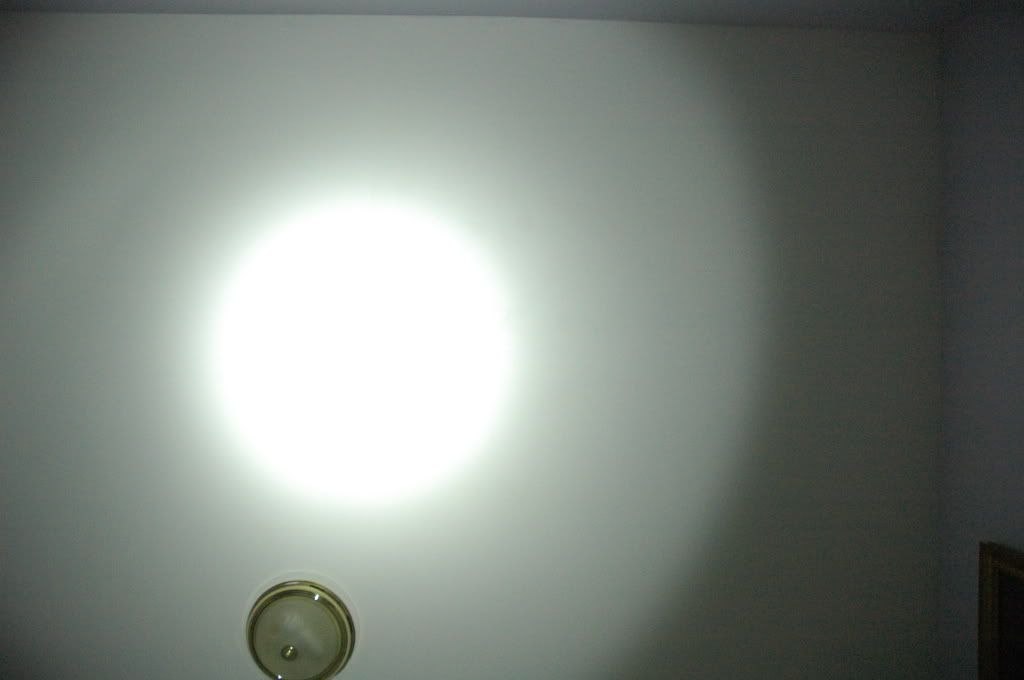
This is a beamshot of the unmodified Minewt Mini-USB for comparison. The hotspot is a lot larger than what I actually see so I had to take some more pictures at a faster shutter speed, which are the next two pictures.
Here's a beamshot of the modified HL-EL510 at a faster shutter speed of 1/15 second. You'll notice that this picture looks almost like the before picture which was taken at an exposure that allows four times more light to be captured. I'd say that this new LED has doubled the light output based on this. Not bad.
Here's the beamshot of the Mini-USB at 1/15 second. The hotspot is a little larger than what I actually see both on the ceiling and out on the open road. This light is rated at about 110 lumens.
I brought both lights outside and compared them but did not take any pictures as it is really foggy outside right now and the pictures would not have been very good. The HL-EL510 is not as bright as the Mini-USB in overall light output but the hotspot is about as bright. It's just that the hotspot is smaller. Mounted low it lights up the road nicely compared to what this light used to do.
Am I happy with this mod? Absolutely. Do I want more output from this light? Absolutely. I really cannot give a good assessment of this mod until I have had an opportunity to take it out on my regular commute. I will report back on Monday evening after I have had a chance to use this light to get home from work.
In a little over a year of commuting by bike I've made a few attempts at bike head lights both to be seen and to see. Everything I've bought so far, except the NiteRider Minewt Mini-USB, has been a disappointment and that includes the HL-EL510. It puts out a decent amount of light for a compact unit but it doesn't put out enough light to see where you are going. Pointing the hotspot about 25 feet out in front of the bike on a completely dark street you can barely make out a lighter spot compared to the surrounding darkness.
Recently, I bought a few Seoul SSC P4 U-bin LED emitters recently from DX and they arrived today. Since the HL-EL510 was a disappointment and it was so easy to take apart and mod I just could not wait so here we go...
Here's the head as it sits, waiting to be taken apart. You carefully pull on the legs, wiggling as you go, being careful not to get the black plastic piece cockeyed in the reflector housing, preventing it from coming out. If you manage to pull the assembly with the legs out then you have to carefully pry the remaining black plastic piece out carefully. Don't pull too hard or you could pull those wires out.
Here's the black plastic assembly removed from the reflector assembly. The two wires go to the heatsink which is attached to the reflector assembly by two small screws. Remove the two screws and the heatsink comes out, too.
Here's the heatsink removed from the reflector assembly. Two more small screws (these are shorter than the first two you removed so don't mix them up) and the plastic shroud comes out. Desolder the LED and you're in ready to replace it.
In the foreground is the new SSC P4 LED waiting to be installed. In the background is the old Luxeon LED. I had to flatten out the contacts before soldering. After removing the Luxeon LED I noticed that there was no thermal compound nor any type of epoxy in place to assist the conduction of heat to the heatsink from the back of the LED. I made sure to dab some on there before soldering the P4 LED in place.
Here's the SSC P4 LED soldered in place waiting for the reinstallation of the shroud. In hindsight, I should have installed the shroud first to hold the LED in place to make soldering the leads easier.
Reassembly is the reverse of disassembly but the parts are keyed to go back together in a certain orientation relative to each other. The heatsink is keyed to attach to the black plastic piece that holds the circuit board in one orientation and the black plastic part with the legs have to go in only one way relative to this, too. The black plastic assembly is keyed to go into the reflector housing in only one way, too. Before assembling everything to the reflector housing I put the heatsink in the black plastic housing assembly then lined up the keys with the slots in the reflector then lined up the tail piece with the legs so that the red line on the one leg lines up with the red line on the reflector assembly then snapped that piece into the housing assembly with the circuit board. I then lined up the heatsink with the reflector assembly and reinstalled that first. The rest just falls into place.
And now, the beamshots against my ceiling. All pictures, except for the last two, were taken at 18 mm, f3.5, 1/4 second, and ISO 800. The camera was tripod mounted low to the ground and the lights were placed on the ground about a foot over from the camera to avoid having the shadow of the camera in the picture.
Here's the baseline shot showing the relative light level in the room. Dark, eh?
Here's the unmodified HL-EL510 headlight beamshot. Those straitions are from the lens in an attempt to widen the beam on the road.
Here's the modified HL-EL510. The hotspot is larger and brighter. The spill is brighter, too.
This is a beamshot of the unmodified Minewt Mini-USB for comparison. The hotspot is a lot larger than what I actually see so I had to take some more pictures at a faster shutter speed, which are the next two pictures.
Here's a beamshot of the modified HL-EL510 at a faster shutter speed of 1/15 second. You'll notice that this picture looks almost like the before picture which was taken at an exposure that allows four times more light to be captured. I'd say that this new LED has doubled the light output based on this. Not bad.
Here's the beamshot of the Mini-USB at 1/15 second. The hotspot is a little larger than what I actually see both on the ceiling and out on the open road. This light is rated at about 110 lumens.
I brought both lights outside and compared them but did not take any pictures as it is really foggy outside right now and the pictures would not have been very good. The HL-EL510 is not as bright as the Mini-USB in overall light output but the hotspot is about as bright. It's just that the hotspot is smaller. Mounted low it lights up the road nicely compared to what this light used to do.
Am I happy with this mod? Absolutely. Do I want more output from this light? Absolutely. I really cannot give a good assessment of this mod until I have had an opportunity to take it out on my regular commute. I will report back on Monday evening after I have had a chance to use this light to get home from work.