
mdocod
Flashaholic
Time to consolidate some of the useful facts about as many of these chargers as possible in one place for easy reference.
I have in front of me a few chargers to compare. I can insert additional information into this post as more information becomes available and testing is completed.
------------
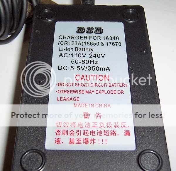
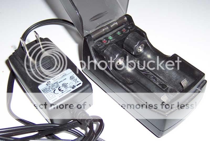
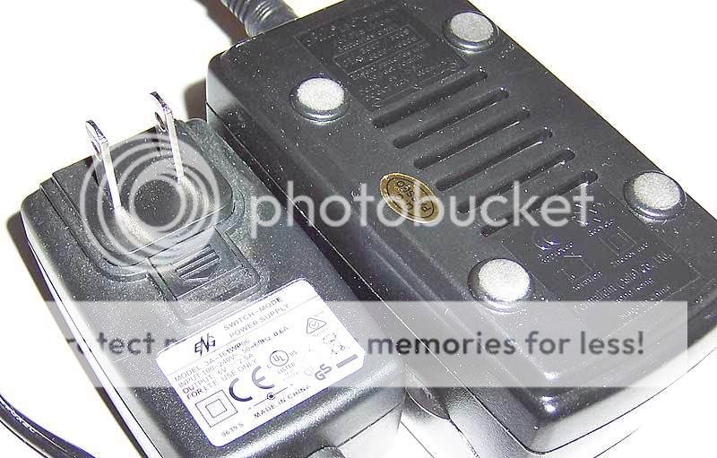
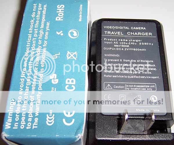
The "infamous" DSD:
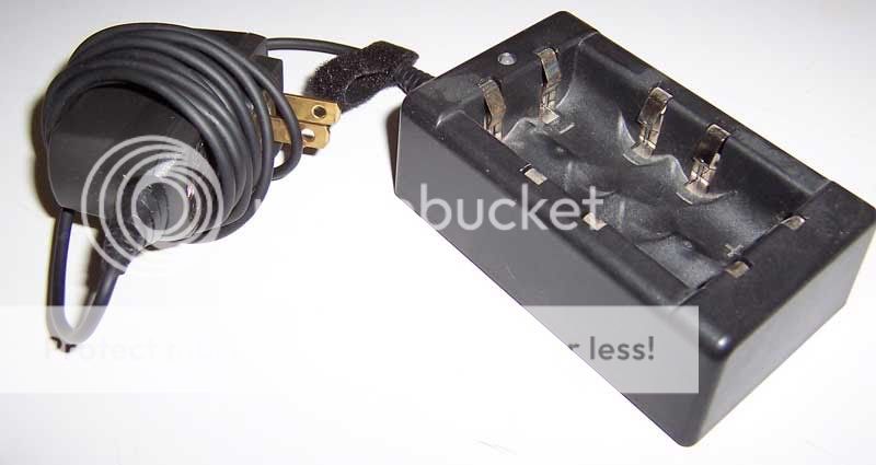
(pictured with a Nokia 800mA power supply)
General Product Information:
Charging Method:
Constant Current at the transformers rated output (aprox) to ~4.25V, followed by true charge termination (no trickle charge).
Safety information/warnings:
------------
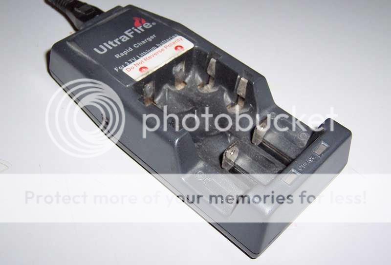
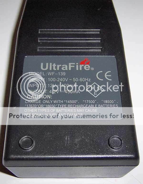
UltrFire WF-139
General Product Information:
Charging method:
Constant Current @~250-350mA per channel (seems to vary) with V-test every ~1 second (pauses charging for a fraction of a second to take the reading) till 4.20V V-test is achieved. Some models appear to have a current ramp down algorithm that kicks in towards the end of the charge but it is not a Constant Voltage charging method. I believe it is the newer versions with the ~5V open circuit behavior that has this ramp down algorithm built in.
Safety Information/Warnings:
------------
Pila IBC
General Product Information:
Charging Method:
Constant Current @ 600mA per channel followed by Constant Voltage @ 4.20V +/- ~0.025V. True termination occurs when charge rate drops to ~50mA under CV stage. The charge rate maintains a constant ~600mA until 4.20V is reached. There is no taper down leading up to 4.2V CV stage. This is the ultimate charge method that provides all of the charge speed possible (given the CC rate) with all of the proper behaviors in place to meet li-ion cell manufacture recommendations.
Safety information/warnings:
Other comments:
Some users complain that the charge is sometimes terminated by lightly bumping the charger or the table that the charger is on during charging... When the charger does terminate as a result of a bump, you have nothing to be concerned about as the charge was approaching the last few minutes of the CV stage of charging anyways. In those final minutes, the charge current is very low, down around 75mA or less. A small bump could introduce enough temporary increase in resistance to cause the current flow to drop below 50mA momentarily which would trip the charge termination. The amount of charge lost here would be minuscule and is not a major issue of concern.
The one major thing that really bothers me about this charger is the fact that it generates a lot of heat. It uses some good electronics to maintain proper charging rate and voltage, but often with charging accuracy comes the sacrifice of efficiency which means heat. With the lid open there doesn't seem to be a problem, everything stays cool. I'm not sure why they even included a "lid" on the charger.
-----------
SoShine SC-S1
General Product Information:
Charging Method:
I think I have this nailed down but be aware that this is all my best educated guess. I did dissemble the unit to take a look at the circuit and components to confirm some of my initial suspicions.
The charging happens in pulses from a capacitor. The capacitor is charged quickly off of the DC power supply and then the circuit between the capacitor and the cell is closed and the capacitor drains off it's power into the cell being charged. When 2 cells are installed in one of the pairs of channels that shares power, the capacitor dumping simply alternates between the 2 channels. So the duty cycle of the charging is cut in half. The effective charge rate is half over time, but the peak charging rate is actually still the same, so smaller cells be-ware.
The charge rate listed on the back of the charger is fairly accurate if you consider it as an average charge rate. Obviously, because of the charge method used here, it actually peaks quite a bit higher at the onset of each pulse.
When the circuit between the cell and capacitor is severed momentarily for the capacitor "charge up" phase, a voltage reading of the cell is taken. When the "resting" voltage reaches ~4.20V the charge is terminated. Each channel has the ability to terminate individually...
Safety Information/Warnings:
Other Comments:
The fact that they slapped a counterfeit UL marking on the back of it bothers me more than anything to be honest. I guess I'm not surprised. If you make a charger with this bad a charging method, might as well just slap some good looking markings on the back of it for good measure. If you've already spilled the paint, might as well spill some more and go wild eh?
----------
Nano (incomplete but this is all you really need to know)
General Product Information:
Charging Method:
Can't recall, tested awhile back, seems like it was a modified taper down IIRC.
Safety information/warnings:
Other Comments:
I do not like this charger.
-----------
CyTac Chargers:
(courtesy CPF member lebox97 @ illuminationgear.com)
lebox97 contacted me and asked if I would be willing to run these 2 chargers through the paces and share the results very publicly. He has provided them to me free of charge in much the same way that several of the other chargers above have been given to me for testing or as gifts.
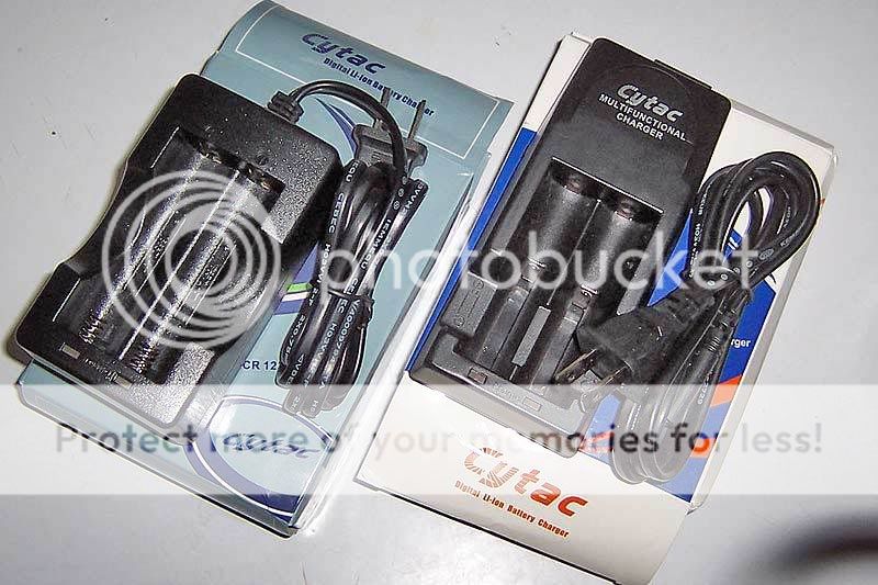
Both Cytac chargers seem to have a lot in common, you will notice I have literally copy/pasted many of the points to be made and only made minor changes to the points based on my measurements.
Cytac 2x18650 charger, "6105/HXY etc"
General Product Information:
Buck regulated 4.25V circuit with no termination current. No CC/CV is present here. The unit does not actually run the full current up to the destination voltage followed by tapering off of current the way a normal CC/CV would work. The current tapers downward in a semi-logarithmic fashion through the charge and never truly terminates.
Some testing:
[resting cell voltage, charge current, charge voltage]
~[3.70V, 870mA, 3.83V]
~[3.80V, 870mA, 3.90V]
~[3.90V, 800mA, 4.00V]
~[4.00V, 590mA, 4.08V]
~[4.10V, 390mA, 4.15V]
~[4.15V, 270mA, 4.18V]
This testing proves that this charger is not a proper CC/CV, and also, shows that the average charging rate is lower than the manufacture claim. I would rate this around 700mA charging rate. The faked termination process is still painfully long to see a green light.
Safety information/warnings:
I have been given confirmation that this is the same as SKU6105 from DX. The nice high charging rate of this charger is totally ruined by the fact that for the last 50% of the charge of the cell, it is constantly tapering down the output. It will take just as long to charge a cell in this as it would to charge with a charger rated for 35% less charge rate and a proper CC/CV method. Perhaps even longer.
----
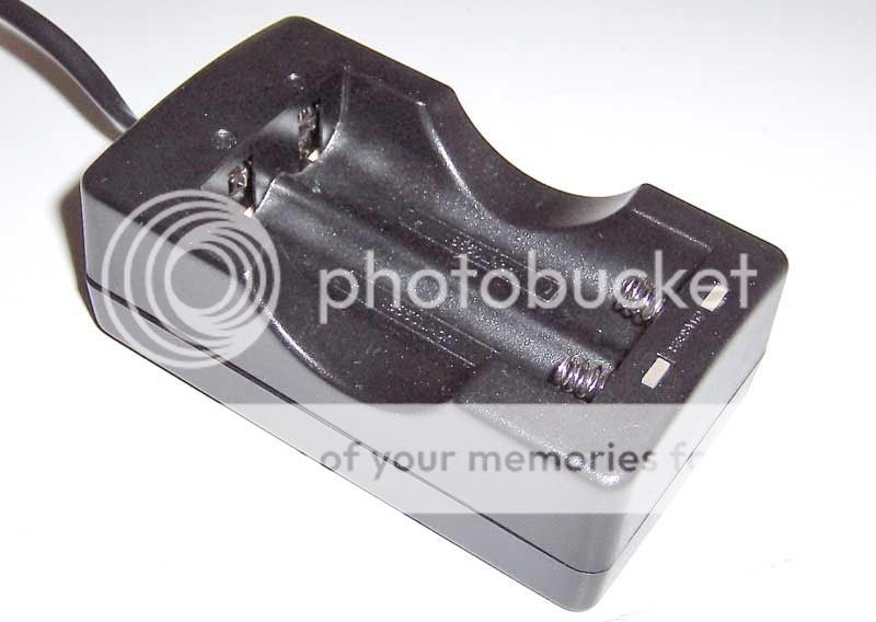
Cytac CY-015 (could this be a TrustFire TR-001/2?)
General Product Information:
Charging Method:
Buck regulated 4.25V circuit with no termination current. No CC/CV is present here. The unit does not actually run the full current up to the destination voltage followed by tapering off of current the way a normal CC/CV would work. The current tapers downward in a semi-logarithmic fashion through the charge and never truly terminates.
Some testing:
[resting cell voltage, charge current, charge voltage]
~[3.70V, 560mA, 3.79V]
~[3.80V, 510mA, 3.86V]
~[3.90V, 440mA, 3.93V]
~[4.00V, 310mA, 4.03V]
~[4.10V, 180mA, 4.13V]
~[4.15V, 110mA, 4.18V]
This testing proves that this charger is not a proper CC/CV, and also, shows that the average charging rate is lower than the manufacture claim. (By my estimates, you can expect about a ~375mA charging rate average). The faked termination point (green light) will take much longer than anticipated based on charge speed claims.
Safety information/warnings:
Other Comments:
As you may have noticed, this charger appears to share a common body with a trustfire TR-001 charger. Other sources have identified that the internal circuit is different from the trustfire. The comments above for the 2x18650 charger about the circuit type likely hold true for this charger as well; Both chargers have the same behavioral traits modified by different charging rates and such. The charging rate of this charger is totally ruined by the fact that through the charge, the charge rate is constantly tapering downward.
-------------------------
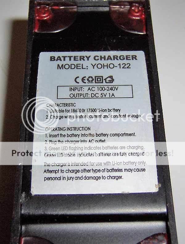
YOHO-122
General Product Information:
Simulated (faked) CC/CV style charging with a final clamp set at 4.20V. Light goes green with cell at 4.20V with ~30mA still flowing, current continues to flow after the light turns solid green. The 1A claimed charging rate over-rated substantially, especially when averaged through the charge. Appears to lack a true termination. Not good. Trickle charge slows to maintain 4.20V as necessary. (no charge termination is present).
What's interesting is that, the unit actually allows charging voltage to rise to ~4.25V early on. Something kicks in, either an algorithm, or triggered by reduced current flow, to pull back the throttle to 4.20V towards the end. This charging method is in a way, sort of like taking the best of 2 charger styles and cramming into 1. Many CC-only chargers charge nice and fast because they skip the slow-down at the end of the charge, the problem is, many of them achieve charging voltages that are higher than what I consider ideal. My feeling is that, in order to be "in compliance" one should try not to exceed 4.25 Vcharge. this charger does this is a way that "cheats out" a fast charge time without introducing unacceptably high charge voltages. In it's own way, this is pretty neat. If i could have this charge method combined with a true termination (no trickle) I would be a happy person.
Some testing:
cell voltage, charge rate/charge voltage
3.70V, 900mA
3.80V, 750mA
3.90V, 650mA
4.00V, 600mA
4.10V, 500mA
4.15V, 460mA/4.22V
Safety/Information/Warnings:
"DX SKU: 22576" 1x18650 charger
(provided for testing by lebox97)
General Product Information:
Charging method:
Steadily diminishing current through the charge. Green light is always on if plugged in, red light comes on when charging, red light begins to dim as the cell approaches the clamped output voltage of the unit. On mine, the red light turns out with the cell at 4.15V and 10mA still flowing to the cell. This charger does not terminate.
Cell voltage/charge current/charge voltage
~3.0V/330mA
~3.7V/260mA
~3.8V/240mA
~3.9V/210mA
~4.0V/180mA
~4.1V/160MA
~4.14V/50mA/4.16V
Safety/Information/Warnings:
Other Comments:
Just another one to add to the list of trickle charging li-ion chargers that should be scrapped.
-------------
"DX SKU 3499" 2x18650 Digital Charger
(provided for testing by lebox97)
General Product Information:
Charging Method:
Holds constant current pretty well up to around 4V at the cell. Followed by a gentle sloping downward in current to the cell/s. This is actually a single channel charger with 2 slots wired in parallel. All of the charging speeds listed below are based on a single cell in a single slot. Adding an additional cell will split the charging speed between the 2 cells. Single LED status light changes from red to green when the cell is ~4.20-4.22V. The green light unfortunately does not mean that it has stopped charging, but, should rather be considered a warning to take the cell out before it trickles it up higher and higher. Like the other chargers I have tested that fail to properly prevent trickle charging, this one will likely try to bring the cell up to an equilibrium with the output voltage. In this case, I would not be surprised to see ~4.26V on a cell if it were left on a few extra hours or overnight by accident.
Cell voltage/charge current/charge voltage
~3.0V/650mA
~3.7V/630mA
~3.8V/630mA
~3.9V/630mA
~4.0V/610mA
~4.1V/510MA
~4.15V/300mA/4.20V
~4.18V/250mA/4.23V
~4.20V/150mA/4.25V
Safety/Information/Warnings:
Other Comments:
There is a UL logo on the box, I suspect it is fake as is the case with every li-ion cradle charger that has carried a UL mark that I am aware of. My theory is, if a company who builds a product does not respect the law of the land in which they intend to sell that product, but even worse, mocks the law in this fashion, should we really trust that they have built a safe product for you? I can tell you that this is not a safe product. Also, the springs are a PITA as they like to fold under as you try to slip the cell into place.
-------------
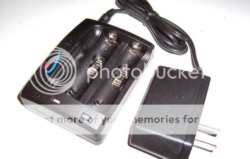
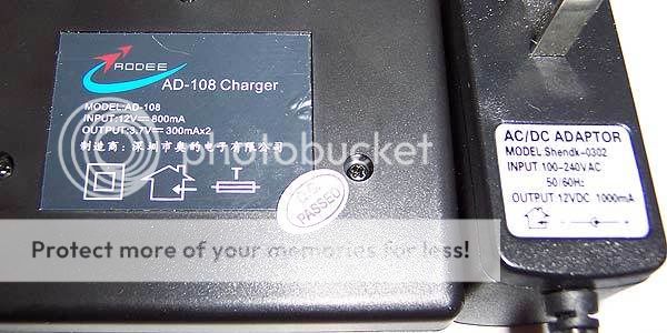
Rodee AD-108
(provided for testing by lebox97)
General Product Information:
Charging Method:
This unit maintains a steady slow pace of ~250mA through the majority of the charge, charging rate starts to taper off above 4.10V (cell voltage, not charging voltage). There is a protection of sorts built in to prevent a charge from being initiated if the cell is above ~4.10V when inserted. I have not figured out what method the charger uses to decide when to terminate. I am not detecting any pulses for a voltage check the way a WF-139 would. I will have to rig up more testing to come to a conclusion.
Cell voltage/charge current
~3.0V/250mA
~3.7V/250mA
~3.8V/250mA
~3.9V/250mA
~4.0V/250mA
~4.1V/240mA
~4.20V/N/A/4.25V
~4.25V/N/A/4.28V
*Will not initiate a "red-light" charge on a cell loaded that is above ~4.10V- however, it does still seem to charge the cell and float it up to over 4.20V.. see below.
Safety/Information/Warnings:
Other Comments:
The springs are pretty lousy, they want to fold down sideways when you are trying to install the cell. The abnormally high open circuit voltage is just weird to me but not terribly worrisome. Charging speed is more appropriate for RCR123s than 18650s IMO.
-------------
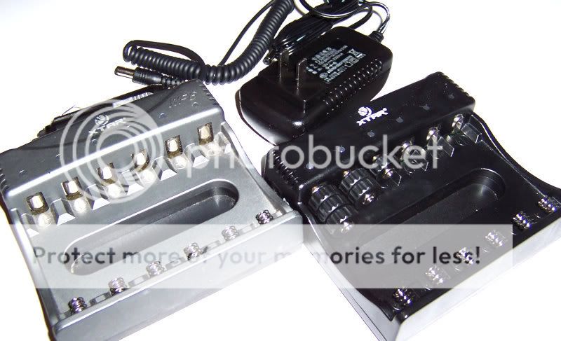
XTAR WP6 and XTAR WP6 II
(Credit to CPF members SilverFox and Jake25 [SBflashlights LLC] respectively)
General Product Information WP6:
Charging Method WP6:
Safety/Information/Warnings WP6:
Other Comments WP6:
-
General Product Information WP6 II:
Charging Method WP6 II:
Safety/Information/Warnings WP6 II:
Other Comments WP6 II:
-------------------------------------
-------------------------------------
Charge Speed Test:
Cytac CY-015: 4.23V@323 minutes
1st Gen WF139: 4.22V@224 minutes
Cytac Digital 2x18650: 4.21V@146 minutes
Pila IBC: 4.19V@123 minutes
YOHO-122: 4.19V@115 minutes
-----
-Eric
I have in front of me a few chargers to compare. I can insert additional information into this post as more information becomes available and testing is completed.
------------
The "infamous" DSD:
(pictured with a Nokia 800mA power supply)
General Product Information:
- Includes a "cell phone" style power supply rated ~350-450mA.
- Included power supply is known for failing when used with 220V service.
- 2 short charging bays to accommodate 2xRCR123 (16340) cells. 2 Long charging bays to accommodate 17670 size cells. 50mm length cells can be fitted with 15mm dummy spacers. 18500 and 18650 cells are a tight squeeze and like to pop out.
- This is a single channel charger that wires any 2 cells installed in parallel for simultaneous charging.
- Nokia cell phone "chargers" can be used as alternative power supplies. Available up to 800mA from what I've seen. Becomes a much better charger with the better power supply IMO.
- Will not initiate charge on cells inserted that are already above ~4.0V unless you manually cycle the input power off and on (unplug and plug back in).
Charging Method:
Constant Current at the transformers rated output (aprox) to ~4.25V, followed by true charge termination (no trickle charge).
Safety information/warnings:
- This is a relatively safe charger when working properly and used properly. The ~4.25V peak charging voltage is actually within the 4.20+/-0.05V recommended maximum charge voltage for most Lithium-Ion cells.
- Because this is a single channel charger, it is important to take into consideration any pair of cells to be installed together in the charger. Ideally, they should be at least roughly matched for voltage. Within a few tenths of a volt would be fine. I would be concerned that if say- a large cell, like an 18650, that was nearly full, were inserted with a nearly dead RCR123, the effective charge current on the RCR123 could exceed maximum safe ratings by a substantial margin.
- Since the power supply is external this charger performs it's duty without any significant heating of the cells.
------------
UltrFire WF-139
General Product Information:
- Accommodates 2 cells. Spring loaded slots will adjust to fit 17500, 18500, 17670, or 18650 sizes. Slots are found for accommodating RCR123s but they are not activated on most units (unit can be dissembled and wires can be soldered in to activate the slots). Most will find that 15mm dummy spacers are the most practical solution to this.
- Independent charging on each channel. Charging is rated at 450mA per channel. This seems to be overrated as most units charge at closer to 300mA per channel.
- Internal power supply, no "wall-wort" transformer consuming valuable space on your rats nest of power cords and power strips.
- Rated for use from 100-240V 50/60hz input.
Charging method:
Constant Current @~250-350mA per channel (seems to vary) with V-test every ~1 second (pauses charging for a fraction of a second to take the reading) till 4.20V V-test is achieved. Some models appear to have a current ramp down algorithm that kicks in towards the end of the charge but it is not a Constant Voltage charging method. I believe it is the newer versions with the ~5V open circuit behavior that has this ramp down algorithm built in.
Safety Information/Warnings:
- The charging method used here is not recommended by any Li-Ion cell manufacture that I am aware of. On smaller cells charging voltage can reach and even exceed 4.35V. Small protected cells will often terminate the charge via PCB.
- Charging voltage in excess of 4.25V may contribute to reduced cycle life and safety problems.
- Older models would continue to trickle charge after the light went "green" and could severely over-charge cells. This is very dangerous. The older model with this behavior can be identified by taking an open circuit voltage reading of a charging bay. The old version will read around ~11V. The new versions will read ~5V.
- The WF-139 will heat cells slightly. The heat seems to be coming from the power supply more so than the cells themselves however. Not a major issue.
- On some units, it has been reported that if a mostly charged cell is inserted into the charger, it doesn't seem to care that it doesn't need to be charged. it will just start charging anyways. The cell can be over-charged at this time as the chargers termination algorithm seems to get thrown out of whack in this circumstance. This could lead to cells being charged right up to 5V which can be extraordinarily dangerous.
------------
Pila IBC
General Product Information:
- Includes a 6V 2.5A power supply "wall-wort" transformer.
- 2 charging slots support 17670 and 18650 size cells. Included spacers can be installed for use with 50mm length cells. RCR123s can be charged by using either an additional 15mm spacer, or a CR123 dummy cell.
- Each channel charges completely independently. Each channel operates at 600mA CC maximum charge rate regardless of whether 1 or 2 cells are installed.
- Includes reset buttons for each channel. (Many li-ion charger electronics will not even initiate a charge if a cell is installed wit ~4.0V or higher, the reset button lets you force the charge to start if you are above ~4.0V at the cell and want to top off).
Charging Method:
Constant Current @ 600mA per channel followed by Constant Voltage @ 4.20V +/- ~0.025V. True termination occurs when charge rate drops to ~50mA under CV stage. The charge rate maintains a constant ~600mA until 4.20V is reached. There is no taper down leading up to 4.2V CV stage. This is the ultimate charge method that provides all of the charge speed possible (given the CC rate) with all of the proper behaviors in place to meet li-ion cell manufacture recommendations.
Safety information/warnings:
- This charger follows quite a few manufactures charge recommendations for their 18650 and 18500 cells to a "T"
- Charge rate is a little on the high side for RCR123s, but since it uses a safer charging algorithm, the higher charge rate is sort of offset by that.
- Charges cool if you leave the lid up; However, with the lid shut this unit traps in some major heat during a charge! Charge with the lid open IMO.
Other comments:
Some users complain that the charge is sometimes terminated by lightly bumping the charger or the table that the charger is on during charging... When the charger does terminate as a result of a bump, you have nothing to be concerned about as the charge was approaching the last few minutes of the CV stage of charging anyways. In those final minutes, the charge current is very low, down around 75mA or less. A small bump could introduce enough temporary increase in resistance to cause the current flow to drop below 50mA momentarily which would trip the charge termination. The amount of charge lost here would be minuscule and is not a major issue of concern.
The one major thing that really bothers me about this charger is the fact that it generates a lot of heat. It uses some good electronics to maintain proper charging rate and voltage, but often with charging accuracy comes the sacrifice of efficiency which means heat. With the lid open there doesn't seem to be a problem, everything stays cool. I'm not sure why they even included a "lid" on the charger.
-----------
SoShine SC-S1
General Product Information:
- Has 4 charging bays for charging up to 4 cells simultaneously.
- *Theoretically* Accommodates cells ranging from 14250 all the way up to 18670 in size.
- Internal switching power supply means no wall-wort transformers consuming your precious plug space on the power strip.
- Each channel has independent termination however channels "I" and "II" share a common power supply, as do channels "III" and "IV." Effective charging rates are cut in half when both slots on the same power supply are loaded.
- Claims 500mA combined charging for channels I and II, 1200mA combined charging for channels III and IV.
- Claims 100-240V 50/60HZ input compatible, also there is a DC 12V input port.
Charging Method:
I think I have this nailed down but be aware that this is all my best educated guess. I did dissemble the unit to take a look at the circuit and components to confirm some of my initial suspicions.
The charging happens in pulses from a capacitor. The capacitor is charged quickly off of the DC power supply and then the circuit between the capacitor and the cell is closed and the capacitor drains off it's power into the cell being charged. When 2 cells are installed in one of the pairs of channels that shares power, the capacitor dumping simply alternates between the 2 channels. So the duty cycle of the charging is cut in half. The effective charge rate is half over time, but the peak charging rate is actually still the same, so smaller cells be-ware.
The charge rate listed on the back of the charger is fairly accurate if you consider it as an average charge rate. Obviously, because of the charge method used here, it actually peaks quite a bit higher at the onset of each pulse.
When the circuit between the cell and capacitor is severed momentarily for the capacitor "charge up" phase, a voltage reading of the cell is taken. When the "resting" voltage reaches ~4.20V the charge is terminated. Each channel has the ability to terminate individually...
Safety Information/Warnings:
- The charging method used is not in accordance with any li-ion cell manufactures I am aware of.
- The charging voltage is hard to measure without an oscilloscope because it's jumps up and down quickly. I have tried to capture some of the points in the charging voltage by quickly cycling the multi-meter on and off to prevent it from having a chance to average the output, the results are scary as I saw high points in the 9V range. Through most of the charge the average voltage is low enough not to trip the PCB.
- Towards the end of the charge, the PCB in protected cells will often start kicking in on every pulse cycle (they are about 2 seconds long). Since the average voltage is above ~4.35V long enough to trip it in those cycles. But since the charge is terminated and re-initiated by the charging algorithm every ~2 seconds, the PCB keeps re-setting and allowing the beginning of the next charge "pulse" to ramp the voltage up again until it trips. This can't be good for the PCB.
- The back of the charger includes a warning that it may cause cells to heat up during charging. It includes a nice spelling error to boot. We all know that a proper charging method should not heat cells much if any. In my testing, even relatively new AW 18650s are heating up in this charger with the lid open.
- If you install a pair of cells of low capacity hoping to split the charging rate between the 2 cells to keep the charging rate within reason, think again. For one thing, the pulses of charge are still at the full rate but the duty cycle is half. For another thing, when one cell terminates, the other cell will be charged at maximum duty cycle for the remainder of the charge.
- Charging voltage in excess of 4.25V may contribute to reduced cycle life and safety problems, this charger exceeds 4.25V during charging by substantial margins.
- This charger has a counterfeit UL listing on the back of it. Isn't that nice? Yes I called UL to confirm my suspicions.
Other Comments:
The fact that they slapped a counterfeit UL marking on the back of it bothers me more than anything to be honest. I guess I'm not surprised. If you make a charger with this bad a charging method, might as well just slap some good looking markings on the back of it for good measure. If you've already spilled the paint, might as well spill some more and go wild eh?
----------
Nano (incomplete but this is all you really need to know)
General Product Information:
- Sold in large numbers over the last few years, especially to folks using smaller RCR2 size and 10440 type cells who needed low charging current for safety.
- Has been included in "kits" with many flashlights that come with their first rechargeable cell and charger.
- Wall-Wart only type charger. (The plug is right on the back of the unit, no cable is included).
Charging Method:
Can't recall, tested awhile back, seems like it was a modified taper down IIRC.
Safety information/warnings:
- Continues to charge after light turns green.
- Over-charges cells to dangerous levels if left unattended.
- Scary think that there are so many out there
Other Comments:
I do not like this charger.
-----------
CyTac Chargers:
(courtesy CPF member lebox97 @ illuminationgear.com)
lebox97 contacted me and asked if I would be willing to run these 2 chargers through the paces and share the results very publicly. He has provided them to me free of charge in much the same way that several of the other chargers above have been given to me for testing or as gifts.
Both Cytac chargers seem to have a lot in common, you will notice I have literally copy/pasted many of the points to be made and only made minor changes to the points based on my measurements.
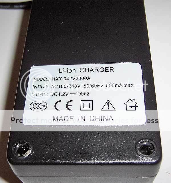
Cytac 2x18650 charger, "6105/HXY etc"
General Product Information:
- 2 independent-channel charging bays intended for use with 18650 size 3.7V cells. My personal educated opinion is that 17670/18500/17500 can also be charged on this charger with care, the 50mm long cells will need a 15mm "spacer" to fill the void.
- Manufacture Claimed output: 1A per channel
- Internal transformer (no wall-warts)
- 100-240V 50/60hz input
- None-Removable 120V wire/plug
- Plenty of room for the really long 18650s (the 18690s
") )
)
Buck regulated 4.25V circuit with no termination current. No CC/CV is present here. The unit does not actually run the full current up to the destination voltage followed by tapering off of current the way a normal CC/CV would work. The current tapers downward in a semi-logarithmic fashion through the charge and never truly terminates.
Some testing:
[resting cell voltage, charge current, charge voltage]
~[3.70V, 870mA, 3.83V]
~[3.80V, 870mA, 3.90V]
~[3.90V, 800mA, 4.00V]
~[4.00V, 590mA, 4.08V]
~[4.10V, 390mA, 4.15V]
~[4.15V, 270mA, 4.18V]
This testing proves that this charger is not a proper CC/CV, and also, shows that the average charging rate is lower than the manufacture claim. I would rate this around 700mA charging rate. The faked termination process is still painfully long to see a green light.
Safety information/warnings:
- Light goes green on mine at ~4.22V
- Does not appear to actually stop charging when the light turns green. The light goes green when the cell is at about 4.22V, but I am still measuring ~70mA flowing to the cell.
- Open circuit voltage is ~4.25V. My gut tells me that it will continue to trickle at a slower and slower pace all the way up to ~4.25V if the cell will continue to rise with the trickle charge.(would depend on the condition of the cell, but basically, any cell left in the charger will be subject to a continuous trickle trying to hold it at ~4.25 V and not settle down as preferred.
- I must reiterate this point, this charger does not terminate at all.
- Li-Ion manufactures do recommend a CC/CV charge method. The importance of a termination without a trickle charge is often emphasized.
- The current ramp-down will trick most novice testers into thinking that it is a CC/CV, but it is not.
- The charge method specified by cell manufactures involves a charging termination based on current dropping to a certain level (usually ~50mA). This charger does not do this, and it does not maintain the CC charge rate to 4.20V either. This will translate to longer than expected charge times that are unnecessary.
- Charging beyond 4.20V is generally frowned upon as cycle life really starts going downhill above 4.20V.
I have been given confirmation that this is the same as SKU6105 from DX. The nice high charging rate of this charger is totally ruined by the fact that for the last 50% of the charge of the cell, it is constantly tapering down the output. It will take just as long to charge a cell in this as it would to charge with a charger rated for 35% less charge rate and a proper CC/CV method. Perhaps even longer.
----
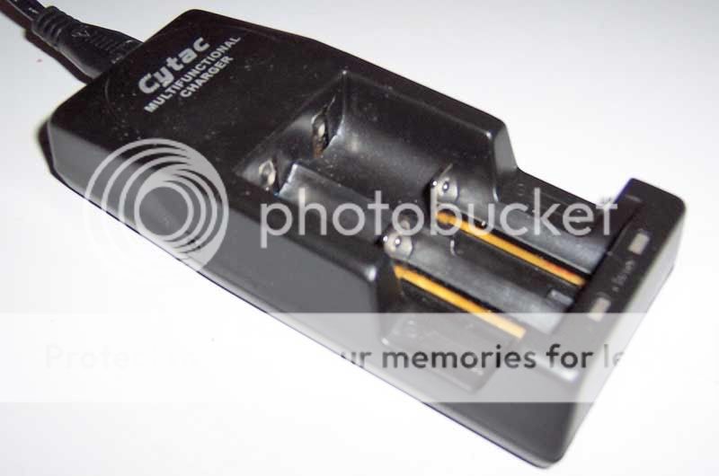
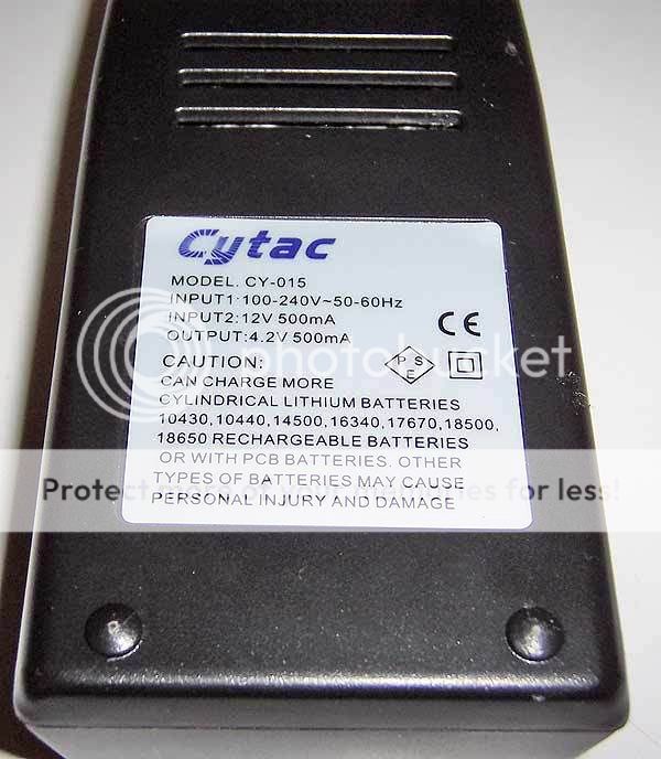
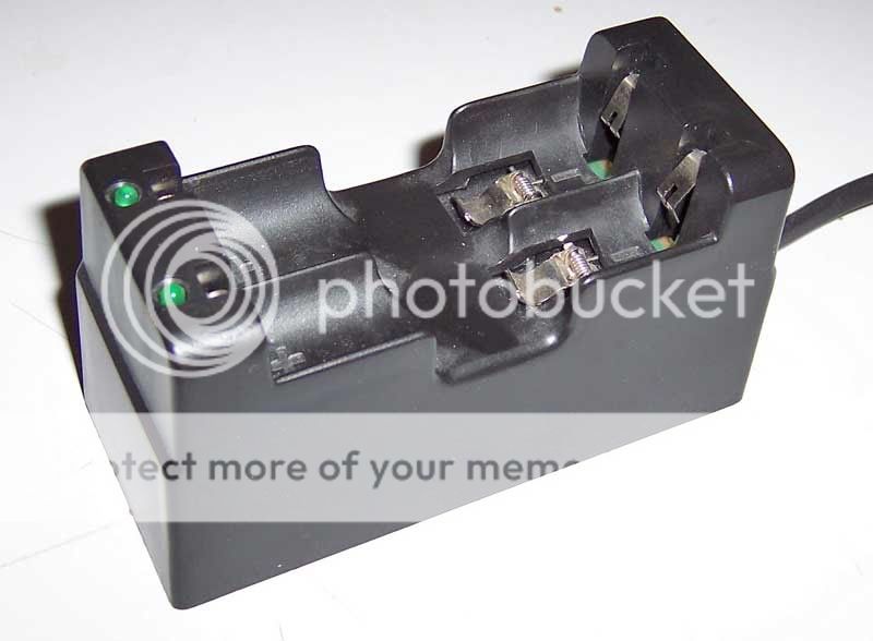
Cytac CY-015 (could this be a TrustFire TR-001/2?)
General Product Information:
- 2 independent-channel charging bays intended for use with 3.7V cell ranging from 16340 (RCR123) size up to 18650
- Manufacture Claimed output: 500mA per channel
- No cell spacers required. Lots of spring travel in the negative contacts
- Internal transformer (no wall-warts)
- 100-240V 50/60hz input
- Removable 120V wire/plug
- Option to run on 12V input (adapter required)
- Plenty of room for the really long 18650s (the 18690s )
Charging Method:
Buck regulated 4.25V circuit with no termination current. No CC/CV is present here. The unit does not actually run the full current up to the destination voltage followed by tapering off of current the way a normal CC/CV would work. The current tapers downward in a semi-logarithmic fashion through the charge and never truly terminates.
Some testing:
[resting cell voltage, charge current, charge voltage]
~[3.70V, 560mA, 3.79V]
~[3.80V, 510mA, 3.86V]
~[3.90V, 440mA, 3.93V]
~[4.00V, 310mA, 4.03V]
~[4.10V, 180mA, 4.13V]
~[4.15V, 110mA, 4.18V]
This testing proves that this charger is not a proper CC/CV, and also, shows that the average charging rate is lower than the manufacture claim. (By my estimates, you can expect about a ~375mA charging rate average). The faked termination point (green light) will take much longer than anticipated based on charge speed claims.
Safety information/warnings:
- Light goes green on mine at ~4.23V
- Does not appear to actually stop charging when the light turns green. The light goes green when the cell is at about 4.23V, but I am still measuring ~20mA flowing to the cell.
- Open circuit voltage is ~4.25V. My gut tells me that it will continue to trickle at a slower and slower pace all the way up to ~4.25V if the cell will continue to rise with the trickle charge.(would depend on the condition of the cell, but basically, any cell left in the charger will be subject to a continuous trickle trying to hold it at ~4.25 V and not settle down as preferred.)
- I must reiterate, this charger does not terminate at all.
- Li-Ion manufactures do recommend a CC/CV charge method. The importance of a termination without a trickle charge is often emphasized.
- The current ramp-down will trick most novice testers into thinking that it is a CC/CV, but it is not.
- The charge method specified by cell manufactures involves a charging termination based on current dropping to a certain level (usually ~50mA). This charger does not do this, and it does not maintain the CC charge rate to 4.20V either. This will translate to longer than expected charge times that are unnecessary.
- Charging beyond 4.20V is generally frowned upon as cycle life really starts going downhill above 4.20V.
Other Comments:
As you may have noticed, this charger appears to share a common body with a trustfire TR-001 charger. Other sources have identified that the internal circuit is different from the trustfire. The comments above for the 2x18650 charger about the circuit type likely hold true for this charger as well; Both chargers have the same behavioral traits modified by different charging rates and such. The charging rate of this charger is totally ruined by the fact that through the charge, the charge rate is constantly tapering downward.
-------------------------
YOHO-122
General Product Information:
- 2 independent charging bays intended for use with 18500, 17670, and 18650 size cells. 17500 cells could also be charged just fine IMO.
- Manufacture claimed 1A per channel charging rate
- no cell spacers required for cell sizes listed above. Pull-up spring loaded contacts for 50mm length cells.
- Internal transformer (no wall-warts)
- 100-240V 50/60hz input
- None-Removable 120V wire/plug
- Plenty of room for the really long 18650s (the 18690s )
- Fastest charger I have tested to date but still falls short of the manufacture claim of 1A charging rates, especially when averaged out.
Simulated (faked) CC/CV style charging with a final clamp set at 4.20V. Light goes green with cell at 4.20V with ~30mA still flowing, current continues to flow after the light turns solid green. The 1A claimed charging rate over-rated substantially, especially when averaged through the charge. Appears to lack a true termination. Not good. Trickle charge slows to maintain 4.20V as necessary. (no charge termination is present).
What's interesting is that, the unit actually allows charging voltage to rise to ~4.25V early on. Something kicks in, either an algorithm, or triggered by reduced current flow, to pull back the throttle to 4.20V towards the end. This charging method is in a way, sort of like taking the best of 2 charger styles and cramming into 1. Many CC-only chargers charge nice and fast because they skip the slow-down at the end of the charge, the problem is, many of them achieve charging voltages that are higher than what I consider ideal. My feeling is that, in order to be "in compliance" one should try not to exceed 4.25 Vcharge. this charger does this is a way that "cheats out" a fast charge time without introducing unacceptably high charge voltages. In it's own way, this is pretty neat. If i could have this charge method combined with a true termination (no trickle) I would be a happy person.
Some testing:
cell voltage, charge rate/charge voltage
3.70V, 900mA
3.80V, 750mA
3.90V, 650mA
4.00V, 600mA
4.10V, 500mA
4.15V, 460mA/4.22V
Safety/Information/Warnings:
- Open circuit voltage of 0.58V
- Will charge over-discharged cells (good or bad thing, depends on your preference) The green light does not come on at all with over-discharged cells, but it is charging.
- Does not appear to actually stop charging when the light turns solid green. The light goes solid green when the cell is at about 4.20V, but I am still measuring ~30mA flowing to the cell. This seems to taper off pretty quickly (a few minutes later, I am measuring ~2.5mA and falling).
- I must reiterate, this charger does not terminate at all.
- Li-Ion manufactures do recommend a CC/CV charge method. The importance of a termination without a trickle charge is often emphasized. this charger lacks that termination.
- The charge method specified by cell manufactures involves a charging termination based on current dropping to a certain level (usually ~50mA). This charger does not do this. It will try to hold a cell at 4.20V all the time. This is not healthy for cells. New cells won't suffer much, but aged cells on this charger for a long period of time could be dangerous.
- This is the only li-ion charger I own that makes a noticeable high pitch buzzing sound.
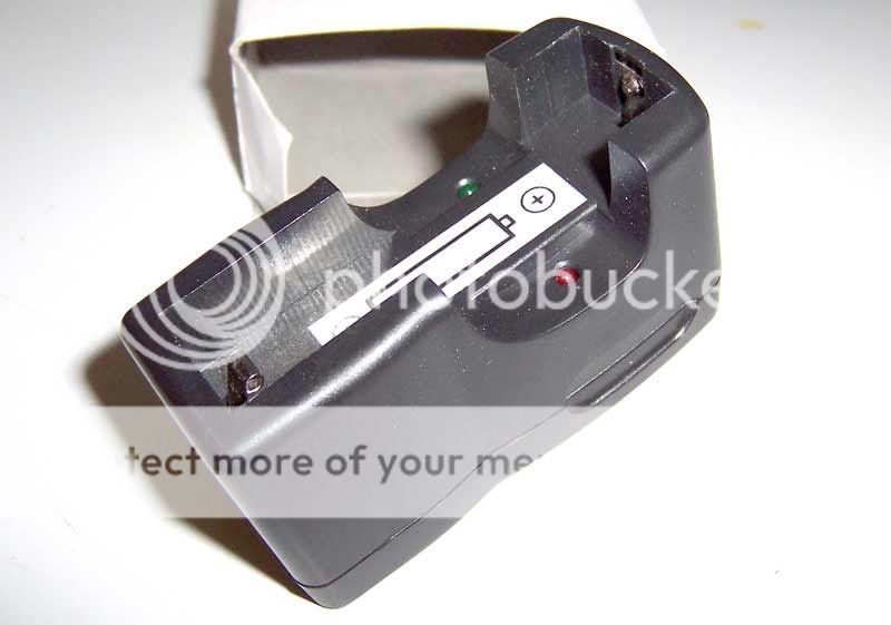
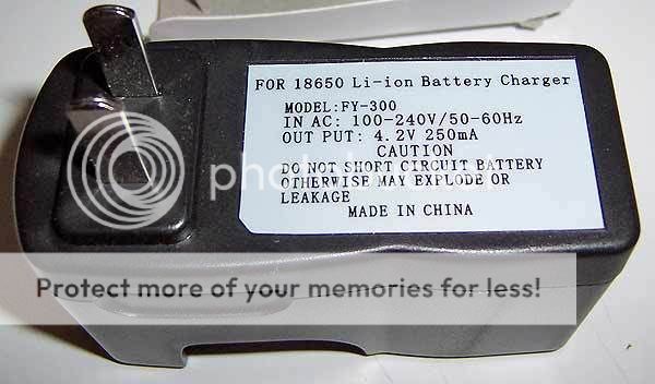
"DX SKU: 22576" 1x18650 charger
(provided for testing by lebox97)
General Product Information:
- Support for 1x18650 size cell, (based on charge rate advertised, I would assume that any size li-ion cell down to ~300mAH capacity could be charged with the appropriate spacers)
- Manufacture claimed 250mA charging rate
- Manufacture claimed "Automatically stops when charging is complete"
- 100-240V 50/60hz input rated
- No cord, spade plug on back (not retractable)
Charging method:
Steadily diminishing current through the charge. Green light is always on if plugged in, red light comes on when charging, red light begins to dim as the cell approaches the clamped output voltage of the unit. On mine, the red light turns out with the cell at 4.15V and 10mA still flowing to the cell. This charger does not terminate.
Cell voltage/charge current/charge voltage
~3.0V/330mA
~3.7V/260mA
~3.8V/240mA
~3.9V/210mA
~4.0V/180mA
~4.1V/160MA
~4.14V/50mA/4.16V
Safety/Information/Warnings:
- Open circuit voltage ~4.17V
- Charge does not terminate but the red light goes out when cell is at about 4.15V
- Again, no termination, this unit will hold a cell at ~4.16-4.17V indefinitely via trickle charging.
- On my sample, the clamped output voltage is so much lower than most of these other "tricklers" that I would feel more comfortable with this charger I suppose. (Most new li-ion cells will hold a 4.20V charge naturally for days or even weeks, so having a charger hold a cell up at 4.17V or so would likely not cause hardly any wear and tear on a new cell. The danger of this charger would kick in as cells age.
- The charging speed is close to advertised if you average it out. Yep folks, unfortunately, it's just as slow as advertised. Plan on a good 10-12+ hours to top up an 18650 if you've drained it off a ways.
- Here's an interesting consideration: If you combine the fact that it takes a really long time to charge, which means that the charge will not be supervised, with the fact that this charger does trickle, it's likely that cells are going to be trickled by this charger because the user is probably going to wind up leaving cell on accidentally for hours and days beyond the charge completing very often.
- Proper termination with absolutely no form of trickle charge is one of the most important considerations in designing a li-ion charger. This charger lacks this important feature.
Other Comments:
Just another one to add to the list of trickle charging li-ion chargers that should be scrapped.
-------------
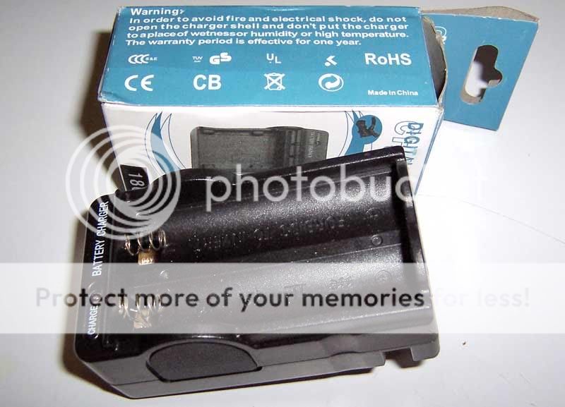
"DX SKU 3499" 2x18650 Digital Charger
(provided for testing by lebox97)
General Product Information:
- Compatible with 3.7V li-ion cells up to 18650 in size. Spacers can be used for most other sizes if charge rate is considered into the equation.
- Manufacture claimed 600mA charging rate
- No cord, flat spade plugs are on a retracting assembly right on the unit.
- 100-240V 50/60hz compatibility
Charging Method:
Holds constant current pretty well up to around 4V at the cell. Followed by a gentle sloping downward in current to the cell/s. This is actually a single channel charger with 2 slots wired in parallel. All of the charging speeds listed below are based on a single cell in a single slot. Adding an additional cell will split the charging speed between the 2 cells. Single LED status light changes from red to green when the cell is ~4.20-4.22V. The green light unfortunately does not mean that it has stopped charging, but, should rather be considered a warning to take the cell out before it trickles it up higher and higher. Like the other chargers I have tested that fail to properly prevent trickle charging, this one will likely try to bring the cell up to an equilibrium with the output voltage. In this case, I would not be surprised to see ~4.26V on a cell if it were left on a few extra hours or overnight by accident.
Cell voltage/charge current/charge voltage
~3.0V/650mA
~3.7V/630mA
~3.8V/630mA
~3.9V/630mA
~4.0V/610mA
~4.1V/510MA
~4.15V/300mA/4.20V
~4.18V/250mA/4.23V
~4.20V/150mA/4.25V
Safety/Information/Warnings:
- Open circuit voltage: 4.27V
- Cells installed together should be in a similar state of charge when possible to prevent high currents from flowing from one cell to another in this parallel wired unit.
- This charger does not terminate, After the light turns green it continues to charge in the same manner as so many of these other chargers I have tested recently.
- Proper termination with absolutely no form of trickle charge is one of the most important considerations in designing a li-ion charger. This charger fails this critical capability and could trickle cells to above 4.25V if accidentally left charging for a long period of time.
- Charging beyond 4.20V is generally frowned upon as cycle life really starts going downhill above 4.20V.
Other Comments:
There is a UL logo on the box, I suspect it is fake as is the case with every li-ion cradle charger that has carried a UL mark that I am aware of. My theory is, if a company who builds a product does not respect the law of the land in which they intend to sell that product, but even worse, mocks the law in this fashion, should we really trust that they have built a safe product for you? I can tell you that this is not a safe product. Also, the springs are a PITA as they like to fold under as you try to slip the cell into place.
-------------
Rodee AD-108
(provided for testing by lebox97)
General Product Information:
- Support for 2x3.7V 17670/18650 size li-ion cells or 2x3.7V RCR123/16340 size cells with pull-up tab connections. Should also work for 14500/17500/18500 with a 15mm spacer.
- Manufacture claimed 300mA charging rate per channel
- External 12V 1A transformer with spade plugs rated 100-240V 50/60hz input
Charging Method:
This unit maintains a steady slow pace of ~250mA through the majority of the charge, charging rate starts to taper off above 4.10V (cell voltage, not charging voltage). There is a protection of sorts built in to prevent a charge from being initiated if the cell is above ~4.10V when inserted. I have not figured out what method the charger uses to decide when to terminate. I am not detecting any pulses for a voltage check the way a WF-139 would. I will have to rig up more testing to come to a conclusion.
Cell voltage/charge current
~3.0V/250mA
~3.7V/250mA
~3.8V/250mA
~3.9V/250mA
~4.0V/250mA
~4.1V/240mA
~4.20V/N/A/4.25V
~4.25V/N/A/4.28V
*Will not initiate a "red-light" charge on a cell loaded that is above ~4.10V- however, it does still seem to charge the cell and float it up to over 4.20V.. see below.
Safety/Information/Warnings:
- Open circuit voltage: ~10.7V
- Charge voltage went to 4.28V on an 18500 with the cell coming off the charger at 4.25V. This is way higher than I would want.
- [edit in 7/18/10]I did some more testing and have come to the conclusion that this charger lacks proper termination and will hold a cell at ~4.26V after the light turns green like many other chargers I have tested.
- Charges below advertised speed
- I suspected that perhaps the high termination was related to me tricking it into re-initiating the charge with a cell above 4.10V (I put another load in parallel for a moment to drag the voltage down a bit and force the charger to re-initiate for testing purposes). I went back and ran charges starting with cells ~4V and it still brought them up to ~4.25V for termination.
- Charging voltage in excess of 4.25V may contribute to reduced cycle life and safety problems.
- Charging beyond 4.20V is generally frowned upon as cycle life really starts going downhill above 4.20V.
Other Comments:
The springs are pretty lousy, they want to fold down sideways when you are trying to install the cell. The abnormally high open circuit voltage is just weird to me but not terribly worrisome. Charging speed is more appropriate for RCR123s than 18650s IMO.
-------------
XTAR WP6 and XTAR WP6 II
(Credit to CPF members SilverFox and Jake25 [SBflashlights LLC] respectively)
General Product Information WP6:
- 6 independent charging bays charge up to 6X 14670-18650 size cells.
- Manufacture claimed CC/CV charging algorithm with termination at 4.2V +/-1%
- Manufacture claimed 600mA CC charging rate (+/-10%).
- AC transformer and car adapter included.
- 6 small magnets included for charging non-button top cells.
Charging Method WP6:
- Cells below ~3V are charged at <80mA until voltage comes up.
- ~550-600mA CC till charging voltage reaches ~3.95-4.0V. In most cases this correlates with a cell SOC of a little over 50%.
- Charge current tapers downward steadily through the final ~40-50% of the charge. Termination seems to occur ~50-100mA.
- Termination voltage from bay to bay varies from 4.18-4.23V. (Each bay is consistent from one termination to the next, but each bay is slightly different than the next bay)
Safety/Information/Warnings WP6:
- Positive contacts in charger are recessed. Even some button top cells have a hard time making contact. Included magnets are a joke of a solution.
- Using charging spacers in the large open bay of the unit for charging shorter cells can be tricky. This is probably why there is no manufacture claimed support for cells shorter than 65mm.
- Open circuit voltage "lobes" from 4.0-4.5V. This does not seem to have any effect on the charge.
- Charger will not initiate a charge on a cell above ~4.1V unless the cell is first inserted, and power is cycled to the charger. (similar to IBC).
- Charger does in fact truly terminate.
- After termination; cells will sit and rest in the charger until resting voltage has dropped to ~4.05-4.10V before the charger re-initiates a top-up cycle. (if the power is cycled to the unit while the cells are resting in the charger, a top-up charge is likely to be initiated, keep this in mind)
- No "float" or Trickle charging after termination. (excellent!)
- Does not qualify as a "true" CC/CV charger because the CC part of the charge doesn't stay constant, however, there is no behavior in the charge process that violates any safety considerations.
Other Comments WP6:
- Properly terminates the charge and does not violate any noteworthy safety considerations for charging li-ion cells.
- If you have lots of 65-70mm long cells with button tops, this charger may prove to be a great value.
- If you are used to the charging speed on a per-cell basis of the Pila IBC, this will disappoint. The CC stage slow-down results in a very drawn out approach to 4.2V.
- Can be added to the very short list of chargers that I would give a passing grade for safety.
-
General Product Information WP6 II:
- 6X independent charging bays
- 6X ~8mm screw-together and screw-in (similar to Pila IBC, but half the length) charging spacers are included
- Manufacture claimed support for 10440/14500/14650/15270/16340/17670/18650/18700 size cells
- Manufacture claimed CC/CV charging algorithm with termination at 4.2V +/-1%
- Manufacture claimed 600mA CC charging rate (+/-10%)
- AC transformer and car adapter included
- Improved cell contacts for wider compatibility than previous generation.
Charging Method WP6 II:
- Cells below ~3V are charged at <100mA until voltage comes up.
- Charging circuitry is "shared" between pairs of charging bays. Counting from the left, bays 1+2, 3+4, and 5+6 are each pairs that effect each-others charging behavior and effective speed.
- A single cell installed into one of these "paired" slots will result in a constant current charging behavior averaging ~550-600mA produced via ~600-650mA charging current with ~90+% duty cycle. The "on-pulses" last about 3 seconds, and are interrupted by very short off-pulses. Any configuration of up to 3 cells loaded where no 2 cells are charging in "paired" slots will result in this charging behavior until the cell reaches ~75% SOC (varies depending on cell resistance). Above that point, the charge current begins to taper off. Pulses stay the same length, but the current during the pulse drops lower and lower through the remainder of the charge.
- A pair of cells installed into a pair of "shared circuitry" clots will results in a constant current charging behavior that averages ~550-600mA via ~1200-1300mA charging current with ~45% duty cycle. The on-pulse trades from one slot to the other equally as the charging progresses. The circuitry can only maintain the 1200+mA current during on-pulses into cells that are still at a relatively low state of charge. The average charging rate for cells above ~40% SOC slows down steadily as the SOC rises, as you may have guessed, the peak current in this configuration is about 600mA when the cell is at about 75% SOC, same as if you're charging a single cell, but in this case, at half the duty cycle per cell.
- In either case above, the final part of the charge comes to a culmination where the charge current (during on-pulses) is ~150mA (varies depending on cell resistance), (either dumped to 1 cell, or split between 2 depending on what you have loaded). Charging voltage can reach as high as 4.25V when charging small higher resistance cells, I have not observed a charging voltage above this, but I have not tested a cell sizes below 16340. The pulses continue until the cell measures 4.21V OC between pulses. Every single bay produces perfectly matched charge states (4.21V in all bays, every time). I believe that all of the charging circuits are probably sharing a common reference for determining termination point.
- Charging slots that share a common charging circuit across a pair of slots (like 3+4) can still initiate charging and terminate charging independently of each-other. Upon the termination of the charge in one of the bays, the cell that is still being charged then gets the full attention of the charging circuit, doubling the duty cycle to the remaining cell. Inserting a cell into a shared bay next to a cell whose charge has completed works fine as well.
- I have observed complete termination. Charging voltage does not exceed 4.25V during charge, final state of charge is spot on and consistent from bay to bay, and cells that are left in the charger after termination are not trickle "floated" as is common in so many other chargers.
Safety/Information/Warnings WP6 II:
- Open circuit voltage: ~2.5V (good!)
- Claimed compatibility with 10440 and 15270 size cells is only true if you are dealing with IMR chemistry cells and are willing to push them hard. I would not suggest charging ICR cells this small in this charger. 16340 is the smallest I would go personally.
- Proper termination and charge voltages that are within the bounds of all serious safety considerations.
- The charger can be tricked into prematurely terminating the charge on all charging bays if certain conditions are met... If any charging cell is removed from the charger, any remaining bays that are charging seem to have about a 50% chance of terminating for no good reason. I have also found a trick that results in a premature termination nearly 100% of the time. The trick to this one is to install a cell that needs to be charged into a bay that shares a charging circuit with an already terminated charge (cell still in place)... After the charge initiates on the newly installed cell, remove it, any other bays that were charging, will terminate prematurely. Pretty silly eh? This behavior is more a nuisance than anything. At first, it will drive you nuts until you figure out what conditions are being met to cause the "failure." Once you know, then you know how to deal with it and when to expect it.
- The previous generation charger would not initiate a charge on a cell above ~4.10V. This charger will initiate a charge on any cell below 4.21V that is inserted. I prefer the previous generations handling of cells ~90% SOC and higher.
- I am not sure if this charger will re-initiate a charge if a cell settles down low enough or not.
Other Comments WP6 II:
- I'm guessing the reason for the ~8mm length spacers is to better accommodate some of those weird cell lengths like the 15270 and 10440. I would have prefered 6x 15mm spacers as they would provide better utility value for most flashlight enthusiasts.
- Charge rate with all bays loaded is not likely to be much better than previous generation charger.
- Charge rate with up to 3 cells loaded in the right places is likely to be quite a bit faster than previous generation charger, but still not as fast as a Pila IBC that maintains 600mA all the way to 4.20V charging voltage.
- New raised positive IBC-copycat style threaded contacts and spacers are a vast improvement over previous design. Sorry- IBC spacers don't quite fit (same thread, but outside diameter of IBC spacers is too large to line up)
- Manufacture failed to list 17500 and 18500 size cells, those should work fine too.
- Not a bad charger all around. Can be added to the very short list of chargers that I would give a passing grade for safety.
-------------------------------------
-------------------------------------
Charge Speed Test:
- Test cells: AW 18500 protected. ~1 year old, a few cycles on them. All from same batch in good condition.
- Each test is performed from a starting and RESTING voltage of 3.70V.
- Charge time is until the charger indicates a "finished" charge with whatever method it uses to convey this information (usually a red LED turning green).
Cytac CY-015: 4.23V@323 minutes
1st Gen WF139: 4.22V@224 minutes
Cytac Digital 2x18650: 4.21V@146 minutes
Pila IBC: 4.19V@123 minutes
YOHO-122: 4.19V@115 minutes
-----
-Eric
Last edited:


