Bluetooth Controlled LedDriver - A Tutorial - Part 10 PC control

mpf

Enlightened
Joined
Oct 2, 2005
Messages
228
Bluetooth Controlled LedDriver - A Tutorial

Bluetooth Controlled LedDriver - A Tutorial
NO SMD Required

For an Android controlled version of this project, see Andriod Controlled Led Driver

This is an extension of the previous tutorial. Build a Basic uC 3 Level Led Driver - A Tutorial https://www.candlepowerforums.com/threads/201383
(or look in Flashlight Electronics - Batteries Included - Threads of Interest)

In this tutorial you will see how to code an RS232 interface for the Atmel Attiny84 and add a bluetooth connection, how to covert the previous ThreeLevelLedDriver to a multiple interrupt structure and how to integrate the RS232 code with the LedDriver. Finally you will see how to modify the driver so that the led is controlled from the computer over the bluetooth connection and the ADC reading, the led current, is sent back to the computer.
The tutorial is also on my website at http://www.forward.com.au/BluetoothLedDriver/BluetoothControlledLedDriver.html

Outline of the Tutorial
i) Introduction - Why add Bluetooth (Posted)
ii) Parts List (Posted)
iii) Building the RS232 circuit (Posted)
iv) What is RS232 (Posted)
iv) Calibrating the uC clock (Posted)
v) How to code uC interrupt driven programs (Posted)
vi) Coding the RS232 module (Posted)
vii) Converting thee ThreeLevelLedDriver to an interrupt driven program (Posted)
viii) Adding the RS232 module to the Led Driver program (Posted)
ix) Controlling the Led from your computer (Posted)
x) Adding the Bluetooth connection (Posted)
xi) Extensions to the project(Posted)

Introduction - Why add Bluetooth?

Adding Bluetooth to my torches was first suggested, in jest, by a work colleague. However then I came across the bluetooth modules sold by SparkFun (www.sparkfun.com) and realised how practical was. What would you use the bluetooth connection for?

1. Remote control of led lighting
2. Configuration/Programming of the torch modes without having to go through multiple complex button press sequences.
3. Monitoring of battery charge
4. Real time debugging of the led controller

Other uses include remote temperature sensing. The Attiny 24/44/84 has a built-in temperature sensor so you can use the bluetooth connection to remotely sense temperature. A more accurate temperature sensor can be made using a NTC resistor (this may be the subject of later tutorial if there is enough interest).

My initial use for the bluetooth connection will be for testing of the development of the battery charger I am building into my torch. The bluetooth connection will allow me to monitor, real time, the uC reading of battery temperature each 30sec while the uC is controlling the battery charging.

Parts List
In addition to the parts and programmer already used for the Basic uC 3 Level Led Driver https://www.candlepowerforums.com/threads/201383 you need the following:-
1 x veroboard
5 x 1uF 25V tag or ceramic caps.
1 x MAX232, an RS232 driver
1 x 3.3 ohm 5W resistor
1 x 16pin IC socket
1 x female 9pin serial connector
1 x serial cable or usb-serial cable
1 x Multimeter with 8Mhz frequency measurement
1 x 6 pin 0.1" pitch, right angle header and matching plug (for the bluetooth module below)
1 x Bluetooth www.sparkfun.com BlueSMiRF-Gold module WRL-00582 (optional see text)
1 x Bluetooth www.sparkfun.com Modem - BlueDongle USB WRL-08180 (optional see text)
1 x USB miniB Cable (www.sparkfun.com CAB-00598 see text)


Parts Discussion
A multimeter with an accurate (<1%) frequency function capable of measuring up to >8Mhz is recommended to trim the uC clock to 8Mhz. Many cheap multimeters
have this function. My circuit ran fine without trimming, so if you don't have this function it might still work for you.

The other parts (excluding the bluetooth modules) are only a few dollars (assuming you already have a serial cable). However the bluetooth modules are US$60 each. They provide a drop in replacement for the serial driver (MAX232) and cable, so you can complete all the coding and operations in this tutorial with out that additional expense. Also if you computer has bluetooth serial capability you won't need the Modem - BlueDongle USB. Sparkfun also offer cheaper USB modules and USB dongles you can use. Sparkfun also sell strips of right angle headers and strips of matching plugs, I used a locally sourced 6 pin header and plug.
 
Last edited:

mpf

Enlightened
Joined
Oct 2, 2005
Messages
228
Re: Bluetooth Controlled LedDriver - A Tutorial

Here is the completed Bluetooth Controlled Led Driver

Bluetooth_BoardSmall.jpg


Last edited:

mpf

Enlightened
Joined
Oct 2, 2005
Messages
228
Re: Bluetooth Controlled LedDriver - A Tutorial

Sorry for the delay it will take some time to write up the tutorial. I have had to spend time in the alternate universe. You know the one where people don't think torches are the most important thing.
 

mpf

Enlightened
Joined
Oct 2, 2005
Messages
228
Re: Bluetooth Controlled LedDriver - A Tutorial

Building the RS232 circuit

Because the the RS232 interface is cheaper then the full bluetooth solution and still allows all the software to be developed and tested we will start with it. It also eliminates the bluetooth setup and connectivity as a possible source of problems.

Here is the completed RS232 version of the project.
RS232_Board.jpg


RS232 Circuit Description

RS232_circuit.png


The circuit has three additions to the previous Led Driver circuit. (http://www.forward.com.au/uCLedDriver/build_basic_uC_led_driver.html) The supply is now 5V as the RS232 driver chip needs between 4.5 and 5.5V. My adjustable suppy had choices of 4.5V and 6V. Do not use 6V as this is too high for both the uC and the RS232 driver chip. I used the 4.5V setting.

This supply is connected to the LED via 3.3ohm 5W resistor. This resistor limits the current to the LED to less then 0.5A and is included as protection so that if the uC turns the controlling FET, U2, on hard for any length of time you do not burn out the LED. This can happen due to programming errors or in the normal course of single stepping through the program in debug mode.

On the right of the circuit, the RS232 driver chip, the MAX232, has been added. The MAX232 is mounted on its own piece of vero board and will be replaced later with a bluetooth module which is also powered by 5V. Finally there is a female 9pin serial connector for connection to the computer.


RS232 Circuit Construction

Take out the attiny84 chip, add the protection resistor and wire up the 16pin socket for the MAX232. If you are using polarised tag capacitors note carefully the polarity shown on the circuit.

Double check your wiring and then with both chips still unplugged, apply power and check that the following voltages. If you are using a 4.5V supply like me than the 5V readings below will be 4.5V instead

  1. 5V at the protection resistor with respect to GND,
  2. +5V between pins 1(+) and 14(-) of the attiny84 socket
  3. +5V between pins 2(+) and 6(-) of the 6pin programming header SV2
  4. +5V between pins 16(+) and 15(-) of the MAX232 socket
  5. 0V between pins 9 and 15 and between 10 and 15 of the MAX232 socket, pins 9 and 10 should be wired to the attiny84
  6. check that the voltage between all pins and pin 14(-) of the attiny84 socket is <= 5V
  7. check that the voltage between all pins and pin 15(-) of the MAX232 socket is <=5V
Plug in the MAX232 only. Leave the attiny84 unplugged.
Apply power and check

  1. -9 to -10V between pin 7 and GND (pin 15)
  2. +5V between pin 9 and GND (pin 15)
RS232 connection to the PC Terminal Software

To connect your PC to a serial device you need some software to talk to the COM port. I use TeraTerm (http://ttssh2.sourceforge.jp) but there are lots of other possiabilities, including Hyperterminal.

With the Attiny84 still unplugged, connect the Serial cable from your computer to RS232 9 pin socket and start your terminal software. When the software starts select the appropriate COM port.
TeraTerm_COMsetting.JPG


Here I am using a USB to Serial Cable converter.
The default serial settings in Tera Term are 9600 baud, 1 start, 8 data, 1 stop and no parity which is just what we want. You can access this setup from the menu Setup → SerialPort...

TeraTerm_ComSetup.JPG


Finally, click in the main TeraTerm window and hold down the 'a' key. You won't see any thing because the local echo option is off (Setup->Terminal, Local Echo tick box) but you should see some reading on your frequency meter connected between pin 9 and GND of the MAX232 chip or between pins 3 and 5 of the serial connector. I read about 120Khz.

This confirms your PC serial connection is working.

Now unplug the MAX232 chip and plug in the Attiny84 chip so we can program it without having to worry about the drive voltage from pin 9 of the MAX232.
 
Last edited:

mpf

Enlightened
Joined
Oct 2, 2005
Messages
228
Re: Bluetooth Controlled LedDriver - A Tutorial - Part 2 added

What is RS232?

Before getting into programming the attiny84, here is some background on the RS232 protocol we will be using.
RS232 is a standard for sending serial data between two devices. It can be either synchronous or asynchronous and can run at various speeds and with various number of data bits, stop bits and parity types. Each end must be pre-set to the particular settings used to transmit the data. For this project we will use 9600 baud, 1 start bit, 8 data bits, 1 stop bit and no parity.

RS232 uses +/- voltages up to +/-25V so never connect a serial cable directly to your uC. Always use a driver chip like the MAX232 which handles the level translation.

The following diagram (from wikipedia http://en.wikipedia.org/wiki/RS-232 ) shows the voltage levels for sending ASCII 'K' (0x4b).
Rs232_oscilloscope_trace.svg.JPG


The MAX232 inverts and shifts the level so that idle become high (+5V) and the start bit is low (0V).

As well as the send and receive lines, the RS232 protocol defines a number of hardware handshake and control lines. Although this tutorial does not use hardware handshaking, they cannot be completely ignored as we will see below.

For outgoing characters, the uC needs to output the required bits at the pre-configured baud rate. For 9600 baud this means the next bit is output 104uS after the start bit is output. With an 8Mhz uC clock this is 833 cycles.

The next figure (from Atmel's application note AVR304) shows the uC sampling points for an incoming character. Note the signal is inverted with idle now +5V. It shows the that the incoming bit stream is sampled at the middle of each bit. The timing of the sample is measured from the falling edge of the start bit. That is, skipping the start bit itself, the first sample is 156uS after the falling edge and then each sample is 104uS after that.
RS232_receiveSamples.GIF

RS232 Hardware Control Signals

Quote from http://www.airborn.com.au/serial/rs232.html
"While the normal PC hardware might well run with just Tx, Rx and Ground connected, most driver software will wait forever for one of the handshaking lines to go to the correct level. Depending on the signal state it might sometimes work, other times it might not. The reliable solution is to loop back the handshake lines if they are not used. When the lines are handshake looped, the RTS output from the PC immediately activates the CTS input - so the PC effectively controls its own handshaking."

These are the connections shown in the RS232 circuit diagram. That is the Request-To-Send (RTS) signal from the PC is looped back to the Clear-To-Send (CTS) input that indicates receiver is able to accept the data from the PC. Of course hard wiring these signals means that the PC will send data just as fast as it can. The Attiny84 needs to keep up or it will miss characters. (This will be discussed more later).

The other links on the 9pin Serial connector, pin 6 to pin 1 to pin 4, connect Data Set Ready to Data Carrier Detected to Data Terminal Ready. The PC drives Data Terminal Ready when it is ready for transmission and this in turn drives the Data Set Ready and Data Carrier Detected which the PC may look for to verify the other end it connected before sending data.
 

mpf

Enlightened
Joined
Oct 2, 2005
Messages
228
Re: Bluetooth Controlled LedDriver - A Tutorial - Part 3 added

Calibrating the uC clock

As discussed above, the RS232 transmission needs to be sent and sampled at precise times. Once each 104uS or 833 uC clock cycles with an 8Mhz system clock. However from the data sheet of the Attiny84, the accuracy of the is only +/-10% (table 20-2) and varies by more then +/-2% with temperature. If the clock is slow by more then about 5.6% then after 1 start bit 8 data bits is will completely miss sampling the last bit and sample the stop bit instead. Conversly if the clock is fast byt more than 5.9%, the 7th data bit when it should be sampling the 8th data bit.

To avoid this happening we are first going to adjust the uC clock frequency to 8Mhz +/-0.08Mhz. My chips initial clock frequency was 7.77Mhz which was within 3% of 8Mhz, so the serial transfer worked for me without calibration. If you don't have a multimeter that can measure 8Mhz, than the serial transfer might just work for you as well. Otherwise you need to follow the calibration procedure below.

Open AVRStudio and start a new project called OscCalibration (see the first tutorial Basic uC 3 Level Led Driver for details on doing this). Load the following code into the empty OscCalibartion.asm file. (This code can be downloaded from OscCalibration.asm)

.include "tn84def.inc"
.def Temp = r16
.def Temp2 = r15

.cseg
// INTERRUPT VECTORS
.org 0x0000
rjmp RESET

RESET:
// set clock to 8Mhz i.e. remove div8 that is set by programmer
ldi Temp, (1<<CLKPCE)
out CLKPR, Temp // enable clock change for next 4 cycles
clr Temp
out CLKPR,Temp // set 8Mhz clock
ldi Temp, 0xA5 // <<<<<<<<<<<<<<<< change this value
out OSCCAL, Temp
MAIN_LOOP:
rjmp MAIN_LOOP

Before loading the program into the attiny84 first use AVR Dragon Fuses tab to turn on the CKOUT fuse. This directs the system clock frequency to PB2 (pin 5).
DragonClockFuse.JPG


Connect your frequency meter between pin 5 and GND

Now goto the AVR Dragon Advance tab and read the clock calibration byte. Don't use the Write button, you only need to Read the byte.
DragonOscByte.JPG


Mine was 0x9E (158). Looking at Fig 21-42 in the Attiny24/44/84 datasheet you can see that this corresponds to more then 7Mhz and less then 8Mhz.

Change the following line in the code
ldi Temp, 0xA5 // <<<<<<<<<<< change this value
Replace the 0xA5 with the calibration value you have just read.


Compile and program the uC with this program. (Remember to change the Hex file to point to your compiled OscCalibration.hex file)
ProgramOsc.JPG


You can then read the actual system frequency corresponding to this calibration setting. If you don't get a frequency reading, check that you have written the fuses with the CKOUT set.

Change value in the program, up or down as necessary, to adjust the frequency to as close to 8Mhz as you can get. Use Fig 21-42 in the Attiny24/44/84 datasheet as a guide. NOTE: Each time the uC starts up it automatically loads the default calibration value, the one you initially read. You should not change from this initial value by more then 0x20 (32 decimal) in one step. If you need to shift the calibration byte value by more then 0x20, then do it in two steps each on less then 0x20. (see the downloaded code file for sample code)

Once you have found the value that gives you 8Mhz at 25degC, you will need to update the other programs in this tutorial with the value you have found.

Finally remember to un-program the CKOUT fuse, to restore the uC to normal operation.
DragonClearClockFuse.JPG
 

mpf

Enlightened
Joined
Oct 2, 2005
Messages
228
Re: Bluetooth Controlled LedDriver - A Tutorial - Part 4 added

An Alternative to Calibration

As an alternative to calibrating the uC clock you could use an 8Mhz crystal or ceramic resonator. The ceramic resonator is has more than enough accuracy and starts up faster. The @page { margin: 2cm } --> disadvantages of these is that they use up two pins on the chip and in this case the pins they need are already being used by the circuit, so you would need to re-arrange the circuit and change the code to refer to different pins. Two capacitors are also needed. 18pF to 22pF seems to be a good start but the Atmel application note, AVR042 AVR Hardware Design Considerations, goes into detail about the best choice of values for these capacitors.
 
Last edited:

mpf

Enlightened
Joined
Oct 2, 2005
Messages
228
Re: Bluetooth Controlled LedDriver - A Tutorial - Part 4 added

How to code uC interrupt driven programs

In this part of the tutorial I will cover some programming tips and guidelines for programming interrupt driven programs. For a general guide to AVR assembler programming try http://www.avr-asm-tutorial.net/avr_en/beginner/index.html and of course read the data sheet for the particular device you are using.

The previous tutorial used a very simple and reliable programming approach. It did all the work in the interrupt routine. The main code merely initialised the uC and then went to sleep waiting for the ADC to finish reading the led current. When the ADC completed, it interrupted the main loop and all the current control and button press handling was done in the ADC interrupt routine.

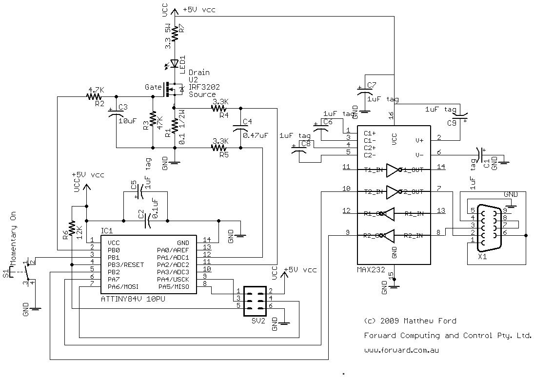
This project will require a more difficult coding style. In this tutorial we need to handle multiple interrupts. These are the ADC conversion complete, the timer1 interrupt for button denounce and general timing, the timer0 interrupt for timing the sending and sampling of the RS232 signals and a pin change interrupt to detect the start of reception of the next RS232 byte.

Tip 1. Make very small changes and always keep copies.

This is the most important tip for programming. Start with the smallest program you can, say set an output low, and then get it to to compile and test it works. Then, most importantly, take a copy of this working program and re-name it version1. I actually prepend 1_ to the code file, e.g. 1_RS232.asm. I also put a comment at the top of the code saying what I changed in this version. Like

// 1 First working code, sets output low Then I make a very small change

to enhance the program and test it again, and so on. I am up to version 44 for the RS232.asm code.

One piece of software that I recommend you buy is BeyondCompare or some other diff program. This will let you easily compare your current code to a previous version so you can see what you have done to stop it working.

A lot of programmers also use version control software like Subversion. For these small projects with just one assemble file it is not necessary, but is very useful as your projects grow in size and complexity. I use the version numbering system while I am away from base and then put the versions into Subversion when I return.

How to Enable an Interrupt

By default all interrupts are disabled. To enable an interrupt you need to

  1. enable the particular interrupt you want by writing to its control register and
  2. enable the global interrupt flag (using SEI)
Guideline 1. Keep the interrupt code small.

While the uC is executing the code in the interrupt routine it, usually, cannot handle any other interrupts. This is because the global interrupt flag is disabled automatically on entering the interrupt routine and turned on again by the RETI instruction at the end of the routine. Level triggered interrupts that come and go while you are handling some other interrupt are not lost, other interrupts are flagged and are processed when the code returns from the RETI instruction. So long interrupt routines mean you may miss some other signals altogether or deal with them after some delay. As we have seen above, the RS232 processing depends on sending the bits and sampling the inputs within a given time. This won't happen if you code spends too long in other interrupt tasks. In general in the interrupt handler just read the data and write it somewhere for the main program to process later.

Guideline 2. Keep global disable of interrupts to as short as possible.

The CLI instruction disables all interrupts and the SEI instruction re-enables the global interrupt flag. If you need to do something that cannot be interrupted, such as moving two bytes from one place to another, then surround the code with
CLI

SEI
to prevent some interrupt routine from changing the registers or global values while you are moving them. This code block should be kept as small as possible.
As stated above, interrupt handlers also globally disable interrupts. Interrupts are disabled on entry to the interrupt handler automatically by the uC and re-enable them on exit (RETI). The reasons given in guideline 1 for keeping the code short also apply here.

Guideline 3. Your main program can be interrupted between any two instructions.

Following guidelines 1 and 2 most of your code should be executed with interrupts enabled. This means that your main program can be interrupted between any two instructions. Because of this, you need to restore the previous values of all Registers and global variable, that do not transfer data, before returning from Interrupt.

If the interrupt changes any of the registers or storage (SRAM) you are working with, then the main program will appear to act strangely. For example, the main program can test some value is greater then 5 and then in the next instruction, after being interrupted, the value is suddenly less than 5. This is the most common problem with interrupt programming, and the hardest to debug. So take special care to guard against this using the programming approaches outlined below.

How to Avoid Interrupt Data Corruption

There are a number of basic ways to overcome this problem of an interrupt changing a register or SRAM value unexpectedly.
There are two basic issues here.

  1. How to prevent interrupt routines from un-intentionally changing the values of registers and SRAM used by other parts of the program
  2. How to main program can safely access registers and SRAM updated by an interrupt routine.
Possible solutions to 1) Preventing un-intentional changes to register and SRAM values, are:-

  1. For SREG, this register MUST be saved and restored by all interrupt handlers.
  2. For general purpose registers, either reserving specific registers for use by specific interrupt handlers, OR by saving and restoring registers used in the interrupt handler.
  3. For I/O and control registers your need retain the values of the bits not being change by the interrupt.
  4. For SRAM, reserving specific locations for use by specific interrupt handlers.
Possible solutions for 2) Safe access to registers and SRAM that is updated by interrupts, are:-

  1. Disable the interrupt inside the interrupt routine and do not enable it again until the main program has finished processing the data. When the interrupt routine returns the RETI will set the global interrupt flag to enable all the other interrupts that you have not disabled.
  2. In the interrupt routine, save the data to an SRAM location and then in the main program copy the data to a different location for processing. If you need to copy more then one byte then surround the code with CLI and SEI to prevent any interrupt changing the data before you can save it.
  3. Make sure your main program has enough time to process the data before the next interrupt can occur. An example of this is processing a denounced push button. The user cannot physically move the button in less then about 0.1 sec and the debounce code will not let the button program status change faster then 10mS (about 80,000 uC clock cycles, more then 40,000 instructions) which is more then enough time for the entire main programming loop to process the button press/release.
  4. Do all the processing inside the interrupt routine itself. Only use this approach for small tasks that don't need to transfer any data to or from the main program. For example flashing a led.
  5. Use 'guard' flags to control access to registers and SRAM locations. These flags let the main program know when it is safe to access and update values that are shared by interrupt handlers. Typically the flags indicate some or all interrupts have been disabled.
Let's look at some examples of applying each of these solutions.

1) How to prevent interrupt routines from un-intentionally changing the values

1) a) Preserving and restoring the SREG register.

This is needed for EVERY interrupt handler so I wrote two small macros.
// start interrupt routine
.macro SAVE_SREG
push Temp
in Temp, SREG // save the SREG
push Temp
.ENDMACRO

// end interrupt routine
.macro RESTORE_SREG
pop Temp
out SREG, Temp // restore the SREG
pop Temp
.ENDMACRO

where Temp is defined as R15. The save macro is used at the very start of the interrupt handler. It first puts the current value of the Temp register on the stack then transfers the SREG to Temp and puts it on the stack as well. This leaves Temp free for use by the interrupt routine. At the end of the routine, just before the RETI statement, the restore macro gets the SREG value off the stack, into Temp, and restores it and then restores the value of Temp the existed before the interrupt routine was called.

1) b) Saving and Restoring General Purpose Registers

My advice is to always save and restore every register you use in the interrupt routine, except of course if you are updating a register for access from the main program or another interrupt routine. You do this by pushing the registers at the start of interrupt routine and poping the in reverse order at the end of the interrupt routine. For example

.def RS232StatusReg = r17 // used in interrupt saved and restored
.def RS232BitCount = r18 // used in interrupt saved and restored
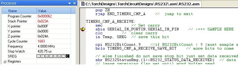
TIMER0_CMP_A_INT:
SAVE_SREG // save Temp and SREG
push RS232StatusReg
push RS232BitCount
...
pop RS232BitCount
pop RS232StatusReg
RESTORE_SREG // restore Temp and SREG and reti
reti // return from interrupt

If on the other hand you decide to allocate specific registers for the sole use of an interrupt routine then you need to carefully document this in your code. I do not recommend this approach because as your code grows you will run out of registers and need to push and pop them as shown above.

1) c) I/O and control registers.

I/O and control registers are shared by the whole program, so when an interrupt routine, or the main program, sets or clears a bit in one of them, you need to make sure the other bits are not changed. To do this you need to use one of two pairs of statements. Which pair you use depends on whether or not the i/o register is in the first 32, i.e. PRR to EEHRH (see the Register Summary in the datasheet).

If the i/o register is in the first 32 you can use SBI and CBI to set and clear individual bits in the register without changing the others. e.g;
sbi PORTA,SERIAL_OUT_A // Set transmit to 1 On the other hand if the register is outside the first 32 you need to load it into a temporary register first and then use SBR or CBR to set or clear the bits you want to change. Note: SBR and CBR are different from SBI and CBI. Where as SBI and CBI only need at bit number, 0 to 7, which you want to change, the SBR and CBR statements need a whole byte mask (0 to 254) to apply. e.g.

in Temp, GIFR
sbr Temp,1<<PCIF1
out GIFR,Temp ; clear pending pin change 1 int.

The 1<<PCIF1 translates to 1<<5 which shifts 1 five 5 places to the left, i.e. 0b00100000, SBR then OR's this mask with the register to set the bit, while CBR AND's the mask's complement to clear the bit

To set or clear more than one bit at a time just OR (||) the masks, i.e.
cbr Temp, (1<<CS02)|(1<<CS01)|(1<<CS00)

Tip: Instead of trying to remember if the i/o register is in the first 32, I just try using SBI, or CBI, and then if the compiler complains I replace SBI, with SBR, 1<< and add the IN and OUT statements

1) d) Reserving specific SRAM locations

SRAM is used for both stack and global volatile storage. Very early in the program you need to reserve some SRAM for use by globals by setting where the stack pointer starts (SP). e.g.

//***** Stack Pointer Setup Code *****
ldi Temp,high(RAMEND-(NO_GLOBAL_VARS+1)) ; Stack Pointer Setup
out SPH,Temp ; Stack Pointer High Byte
ldi Temp,low(RAMEND-(NO_GLOBAL_VARS+1)) ; Stack Pointer Setup
out SPL,Temp ; Stack Pointer Low Byte There are two coding statements you need to The RAMEND is defined in the include file for each AVR uC. The NO_GLOBAL_VARS is a variable I define at the top of the code. Note: the +1 to allow for global variable 0.

When I set the NO_GLOBAL_VARS, I also define a place holder for each one of them i.e.
...
.equ GLOBAL_27 = RAMEND-27
.equ GLOBAL_28 = RAMEND-28
.equ GLOBAL_29 = RAMEND-29
.equ GLOBAL_30 = RAMEND-30

Then as I use them I replace the GLOBAL_.. with the name of the variable. If I run out, I increase NO_GLOBAL_VARS and add more place holders. Your code should clearly comment the use of each of these SRAM locations.

2) How the main program can safely access Registers and SRAM updated by an Interrupt routine.

2) a) Disable the interrupt inside the interrupt routine.

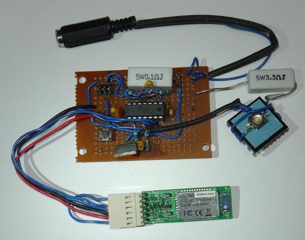
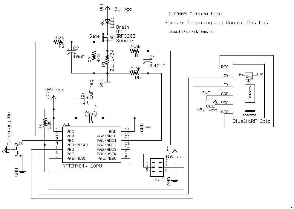
A slight variation of this approach is used in the LED_CONTROL processing in the BluetoothControlledLedDriver.asm (to be posted later). In this case the interrupt routine does nothing (actually is not defined). The ADC is set for single conversions and stops when the conversion is complete. The main program looks for the conversion complete flag and processes the reading, before starting the next conversion. So there is no possibility of the ADC reading being changed while the main program is processing them. This is also an example of Polling. That is where instead of having an interrupt routine, the main program just loops check to see if something has happened. This approach is not suitable for time critical applications.

2) b) Save the data to SRAM, then copy to a different location

An example of this from RS232.asm (to be posted later) is

lds Temp, RS232_STATUS
sbrc Temp, RS232_STATUS_TX_COMPLETE
The Timer0 Compare A interrupt, and others, update the RS232_STATUS SRAM location. The main program reads this location it to a register and then tests for various statuses. Since only one statement is need to read the byte, you don't need to surround the statements with CLI, SEI.

On the other hand if we want to set/clear a bit in an SRAM location that is updated by an interrupt, you need to make sure the interrupt routine does not try the value while the main program is trying to change the value. So we surround the main program's update statement with a CLI and SEI statements to stop any interrupt handler from interrupting this group of statements.

// clear RS232_STATUS_DATA_RECEIVED
// disable of interrupts to prevent some other interrupt change the RS232_STATUS
// after we load it and before we save it. If so then that change would be lost.
cli
lds Temp, RS232_STATUS
cbr Temp, (1<<RS232_STATUS_DATA_RECEIVED)
sts RS232_STATUS, Temp
sei

2) c) Make sure your main program has enough time to process the data before the next interrupt occurs.


In the BluetoothControlledLedDriver.asm (to be posted later), a timer interrupt checks the button position and updates the SwitchChanged flag. The main loop checks this flag each time round the loop and if it is set it clears the flag and then checks the button position. The code only works if the SwitchChanged flag and button position cannot change in the time it takes the program to do an entire loop. The SwitchChanged and SW_SWDown flags can only be updated once per 10mS. This is more then enough time for for the uC to execute and entire loop of the main program. So if the flags change just after this code is executed, they will still be valid next time the program loop comes around.

sbrs TRIGGER_Flags, TRIGGER_SwitchChanged
rjmp Finished_SwitchChanged_TRIGGER_PROCESSING
// else changed clear trigger now
cbr Trigger_Flags, (1<<TRIGGER_SwitchChanged)
// else switch changed state, check switch state
// clear the trigger
sbrc SW_Flags, SW_SWDown // skip rcall if switch is up
rcall PROCESS_SWDown_TRIGGER // set level accordingly

2) d) Do all the processing inside the interrupt routine itself.


The handling of the RS232_SEND_WORD in the Timer0 Compare A interrupt handler is an example of this (see RS232.asm to be posted later). This SRAM location is not used at all by the main program. All modifications are done in the interrupt handlers. So there is no possibility that its value can be changed by the main program.

2) e) Use 'guard' flags to control access to registers and SRAM locations.

This is a very common means to controlling access to shared registers and SRAM locations. In BluetoothControlledLedDriver.asm (to be posted later), the RS232_STATUS location is used to communicate the current status of the RS232.
For example when the RS232_STATUS_BUSY is set, the link is sending or receiving and it is not safe for the main program access or update the send/receive data. So the main program can load this status byte, using method 2) b), and then check the value of RS232_STATUS_BUSY and RS232_STATUS_SEND to see if it is safe to update the data to be sent. Note: that this code depends on RS232_STATUS_SEND remaining false at the end of sending until the main program starts another send, using 2) a) above.

lds Temp, RS232_STATUS
sbrs Temp, RS232_STATUS_BUSY
rjmp SEND_ADC_READING_TRANSMIT // not busy so can send
// if busy see if sending or receiving
sbrc Temp, RS232_STATUS_SEND
rjmp END_SEND_ADC_READING // busy sending so keep trigger and try later
// else not busy sending so send this reading
// Note RS232 may be busy receiving.
// If so this transmit will just terminate the receive
// if it has not finished by the time RS232_TRANSMIT is called below
SEND_ADC_READING_TRANSMIT:

Since we have not put these tests in a CLI, SEI block, an RS232 receive could start after we tested the RS232_STATUS_BUSY flag, or as noted in the code there could be a receive already in progress. In either case, as documented in the code, the transmit will take precedence and terminate any receive that is in progress.

2) f) Update the register atomically

Updating the register atomically means doing it in such a way that an interrupt can not disrupt the update. In practice this usually means doing the update in a single statement, such as

cbr Trigger_Flags, (1<<TRIGGER_Timer1)

which clears a bit in the Trigger_Flags register in one instruction. Interrupts never interrupt a single instruction and this instruction does not change any of the other bits in the register. Some Atmel uCs also provide atomic access or update to a pair of registers which guarentees that once you read/write the first register the second will not be changed before you read/write it. For example, in the Attiny84, when you read the low byte of the ADC result register it blocks the update of the result until the high byte has been read.
 
Last edited:

mpf

Enlightened
Joined
Oct 2, 2005
Messages
228
Re: Bluetooth Controlled LedDriver - A Tutorial - Part 5 added

Coding the RS232 Module

There are a number of ways you can code an RS232 interface on Atmel processors. For the larger processors, a hardware UART is provided. For the smaller processors, such as the Attiny84 used here, there is no hardware UART. The Attiny84 does have a USI hardware function for SPI communication. This can be also used as part of an RS232 interface (see Atmel application note "AVR307: Half Duplex UART Using the USI Module" for a C code version) However this restricts the pins you can use to the DI and DO pins. Atmel application note AVR305 provides a simple RS232 implementation, which can use any pins. Unfortunately the timer is implemented as a software loop so there are no cycles left for the processor to do anything else while it is sending or receiving. AVR274 provides a single wire timer based solution, where the send and receive bytes both use the same pin. This is not suitable for our application. One suitable alternative to the code presented here is a software based RS232 assembler code module from http://www.siwawi.arubi.uni-kl.de/avr_projects see the Software-UART (softuart_gittins) project on that page.

The code used here is a software base implementation using one of the hardware timers and providing half duplex RS232 on user selectable pins. The source code is in RS232.asm. As provided, it is configured for 9600 baud 1 start, 8 data and 1 stop bit half duplex transmission using PA7 for receiving and PB2 for transmission. To use other pins change the defines at the top of the code. To ensure the baud rate is accurate you should set OSC_CAL_STEP_1 and OSC_CAL_STEP_2 to clock calibration setting you determined from running OscCalibration above.

This code is designed to provide RS232 capabilities to your other programs. There are three routines you need to call:-
RS232_INIT which initialises the pins and timer0 and the interrupts,
RS232_TRANSMIT which transmits the bytes previously saved in the RS232_BUFFER_1 to n, where the number of bytes to send has been stored in RS232_SEND_COUNT
RS232_SET_TO_RECEIVE which sets the software to detect a start bit and start receiving a byte.

To see how to use this module look at the test program that is included, starting at RESET. This test program waits for a character to arrive and then echos back the character in hex, prefixed with "Received " and terminated by <cr><lf>

After setting the system clock, allocating space for the global SRAM variables and calibrating the system clock, the program loads the RS232_BUFFER locations with the fixed part of the return message. Then it calls RS232_INIT to initialize the RS232 module and then globally enables interrupts.

Then the program calls RS232_SET_TO_RECEIVE to set up for the receiving the first char and go into an infinite loop calling PROCESS_RS232.
In each call to PROCESS_RS232, it check the state of the RS232 module. This is called polling. If the RS232 module has just finished transmitting, i.e. RS232_STATUS_TX_COMPLETE is set, then we call RS232_SET_TO_RECEIVE to wait for the next character to arrive. Calling RS232_SET_TO_RECEIVE clears the RS232_STATUS_TX_COMPLETE for us.
If RS232_STATUS_TX_COMPLETE is not set then we test if RS232_STATUS_DATA_RECEIVED is set, if not we return to the main program which loops and calls PROCESS_RS232 again.
If RS232_STATUS_DATA_RECEIVED is set then we load the byte received and clear the flag to indicate we have copied the byte out of the buffer. Then we convert the byte to HEX and save the two numbers in the correct RS232_BUFFER locations, then set the RS232_SEND_COUNT and call RS232_TRANSMIT to send the all the bytes.

Of course in the background, while the statements in PROCESS_RS232 are being executed, the RS232 module's interrupts are interrupting the execution as necessary to send and receive the bytes.

Limitations of this RS232 Module

The software RS232 Module presented here, while suitable for its intended use, does have some limitations. These are:-
i) It cannot send and receive at the same time. Not a big limitation and the software to overcome this would be messy.
ii) When you are transmitting you can miss incoming characters, or when you stop transmitting and call RS232_SET_TO_RECEIVE, you might start to receive a byte half way though and get the wrong character. You can use the additional drivers on the MAX232 chip and extra pins on the Attiny84 to implement hardware handshaking to stop the PC from sending characters until you are ready to receive them. Another alternative is to be tolerant of bad characters or check them with a CRC check sum or by echo them back to the sender for verification.
iii) Noise on the receive line can trigger the pin level change interrupt and cause the uC to think there has been a start bit and start sampling the input and return garbage for the received character. This could be a problem in noisy environments, but I have not had any problems like this with this circuit.

None of these limitations are serious problems for controlling the Led Driver using RS232 / Bluetooth

Testing the RS232 Module

Start a new project, RS232 (see the first tutorial Basic uC 3 Level Led Driver for details on doing this). Download the code from RS232.asm and load it into the empty RS232.asm file the project created. Compile the code. Because timing is critical to the correct transition and reception of bytes, you cannot debug this code using the Dragon in-circuit debugger. Instead this code is more easily debugged using the ARV Studio simulator. The debug example below shows how to trace through the code and check that the receive sample times are correct.

In AVR Studio select the menu items Debug, Select Platform and Device. In the dialog that appears, select the AVR Simulator for the Platform and select the Attiny84 for the device.
SelectSimulator.JPG


Then, after compiling, set a breakpoint at
rcall PROCESS_RS232
line in the main program. Then start debugging using the Debug, Start Debugging menu item and then once debugging has started use Debug, Run to run to the break point. Now we are going to toggle the RS232 receive pin (PB2) to simulate a start bit arriving. This will trigger the pin level change interrupt. First take note of the current clock counter, 434, and stop watch 108.5uC, in the debugger.
StartClockCounter.JPG

Note that the Simulator uC frequency is set to 4Mhz, where as the circuit will actually be running at 8Mhz so all the times shown in the simulator need to be halved.

Now toggle the PB2 input pin in the PINB I/O view. As you move the mouse over the pins, AVR Studio will display their names.
PINB_PB2.JPG


Clicking on the square toggles the pin and changes the hex value (shown in red). Before continuing the run, set a breakpoint at the first line of the PIN_CHANGE_INT:, that is on the SAVE_SREG line. Then selecting Debug, Run again the simulator will stop at this point a few cycles later. So the pin change interrupt is working. Now set a breakpoint in the TIMER0_CMP_A_INT at the line that says

sbis SERIAL_IN_PORTIN,SERIAL_IN_PIN // <=== SAMPLE HERE This is
where the receive bit is sampled for each bit.

Choose Debug, Run again. The program will stop on your first breakpoint at rcall PROCESS_RS232. Remove this breakpoint and run again. When it stops at the breakpoint inside TIMER0_CMP_A_INT at the sample point, the cycle counter reads 1683 and the stop watch reads 420.75uS
FirstSample.JPG

i.e. there were 1683-434 =1249 clock cycles between changing the input receive pin and the first sample. At 8Mhz 1249 cycles is 156.125uS. One and half bits periods of 9600 baud is 1.5 x 1/9600 = 156.25uS or 1250 cycles. So we are very close to sampling in the middle of the first bit after the start bit. The difference in the stop watch is 312.25uS with a 4Mhz clock. With our two times faster 8Mhz clock, the time is half or 156.125uS. You can continue to run the software debug simulator and see when the next bits will be sampled and then to confirm when the send bits will be switched.

Loading the RS232 Module

Now that you have checked that the software will sample the receive bits at the correct time and send the bits at the correct time you can load the RS232.asm code into the Attiny84. Open the AVR Dragon programming dialog and in the Main tab set the path for both the RS232.hex and RS232.eep files. This code has eprom data which contains the constant part of the return string, so you need to program both the HEX and EEPROM files.

Remember the MAX232 chip is still removed. You tested it previously. Now you will test the uC is receiving and sending its signals on the correct pins on the MAX232 socket.
RS232_Programming.JPG


To program the uC, Erase the Device and program both the Flash and EEPROM.

To test the uC receive and send, connect you Frequency meter (or volt meter if you don't have a frequency meter) between pin 10 of the MAX232 socket and ground. The touch pin 9 of the MAX232 socket with a grounded wire. This will trigger a pin change interrupt in the uC and in turn send a series of bytes back to pin 10 of the MAX232. Your multimeter should show some fluctuation as the bits toggle on and off.

Communicating with your uC

Now that you have some indication that the uC software is actually working, you can turn off the power supply and fit the MAX232 chip and connect the serial cable to your computer. Start TeraTerm ,or whatever terminal software you are using, and configure it to talk to your serial port at 9600 baud, 1 start, 8 data, 1 stop, no parity as you did above in "RS232 connection to the PC Terminal Software". Local echo is off by default in TeraTerm, so to see the characters you type, turn it on by selecting the menu items Setup, Terminal and checking Local Echo
LocalEcho.JPG


Now press a key, say 1 and you should see
1Received 0x31
try some more keys, each time your uC should respond with hex value of the key you pressed.
RS232_test.JPG


As discussed above under "Limitations of this RS232 Module", if you manage to send characters faster then your uC can handle them, you will get back corrupted hex values, indicating the uC did not receive the byte correctly.
 

mpf

Enlightened
Joined
Oct 2, 2005
Messages
228
Re: Bluetooth Controlled LedDriver - A Tutorial - RS232 Software added

Converting the Three Level Led Driver to an Interrupt Drive Program

The Basic uC Led Driver that this tutorial is based on used a very reliable and easy to program method of handling the Analogue to Digital Converter (ADC) interrupt. It used method 2) d) "Do all the processing inside the interrupt routine itself." However while this is OK if there is just one interrupt, when you have to handle more then one interrupt it breaks Guideline 1 "Keep the Interrupt Code Small" Executing large blocks of code in the interrupt routine delays the handling of other interrupts. As we have seen in part 1, sending and receiving RS232 signals is time critical. So before we integrate the RS232 module into the Led Driver, we must first modify the Led Driver to be an interrupt driven program where the interrupts are handled quickly.

The original Led Driver code is in ThreeLevelDriver.asm , the revised code is in 3LevelDriver.asm. Most of the the code is the same. The main difference is that
i) the Led Control code and the Process State Triggers code is now called from the main loop,
ii) the ADC interrupt routine has disappeared and
iii) there is a timer interrupt routine.

First lets look at how the ADC measurements are collected. Instead of using an interrupt we just "pole" the ADSC flag to see if the ADC has finished converting the next sample.

LED_CONTROL:
sbic ADCSRA, ADSC
rjmp RET_LED_CONTROL // ADSC still set no reading yet

If it has not finished then, the LED_CONTROL routine just returns, otherwise it reads in the ADC sample, starts another conversion and drives the led control output in the same way as the original code did. Since the next conversion is not started until the last sample has been read, there is no possibility of losing a sample or having it partially over-written by a new value while we are still processing it.

Next look at the timer interrupt. This is similar to the RS232 timer interrupt but using a different timer. Timer1 is set up to fire an interrupt every 2mS. The interrupt routine is very short and simple

TIMER1_COMPARE_A_INT:
SAVE_SREG // not used here but leave as standard interrupt preamble
sbr TRIGGER_Flags, (1<<TRIGGER_Timer1) // modifies SREG
RESTORE_SREG
reti

It just sets a flag and returns. A routine in the main program, TIMER1_2mS, checks this flag and calls SWITCH_DEBOUNCE each time it is set.

TIMER1_2mS:
sbrs TRIGGER_Flags, TRIGGER_Timer1
rjmp END_TIMER1_2mS
// else changed clear trigger now
cbr Trigger_Flags, (1<<TRIGGER_Timer1)
rcall SWITCH_DEBOUNCE
END_TIMER1_2mS:
ret

You can see a pattern developing in this program and the RS232 program. The interrupt routines do the minimum work possible, save results and then set flags to alert the main program that data is available or has been sent or that some action has happened.

The main program loop is

MAIN_LOOP:
rcall LED_CONTROL
rcall TIMER1_2mS
rcall PROCESS_STATE_TRIGGERS
rjmp MAIN_LOOP

The interrupts set the flags and save results and these three routines called from the MAIN_LOOP look for changes in the flag settings and use the results to control the led and process the push button presses.

The rest of the code of 3LevelDriver.asm is very similar to the previous ThreeLevelDriver code, pushing the button changes the state and loads a new led current set point. Note that because the led control and the loading of the new led current set point are called from the main program loop and not from the interrupt routine, there is no possibility of set point being changed half way through the led control routine, LED_CONTROL

To program the uC, start a new project, 3LevelDriver, as described in the previous tutorial Basic uC 3 Level Led Driver , and downloaded the 3LevelDriver.asm and copy it into the empty .asm file created by the project. Compile the code and program the uC. Remember to change the Input hex file to the 3LevelDriver.hex file on the Program tab of the AVR Dragon programming dialog.

You led driver should run as it did in the previous tutorial, with the button click cycling through the 3 levels of led brightness and then off.
 

mpf

Enlightened
Joined
Oct 2, 2005
Messages
228
Re: Bluetooth Controlled LedDriver - A Tutorial - Part 8 added

Made mod to RS232.asm to allow this module to be used in a program which has other interrupts happening. Updated code here RS232.asm
 

mpf

Enlightened
Joined
Oct 2, 2005
Messages
228
Re: Bluetooth Controlled LedDriver - A Tutorial - Part 8 added

Adding the RS232 module to the Led Driver program

The last bit of software programming that needs to be done it to merge the RS232 module with the 3LevelDriver. The merged code is in BluetoothLedDriver.asm.

In this code the three methods of the main loop of the 3LevelDriver above have been moved to their own method, LED_CONTROL_PROCESSING and two new method have been added to the main loop, PROCESS_RS232 and SEND_ADC_READING.

The PROCESS_RS232 method processes the incoming characters from the RS232 module. '0' turns the led off, '1' sets low level, '2' sets medium level and '3' sets high level. Also 'u' and 'U' will increase the led setpoint while 'd' and 'D' will decrease it.

The SEND_ADC_READING method handles sending the ADC current reading back to the PC via the RS232 connection.

PROCESS_RS232

PROCESS_RS232 first checks if the RS232 module had just finished transmitting (the ADC reading) and if so sets it to receive characters. Otherwise the code checks if there is a new data byte has been received to be processed. Note the can occur even if the RS232 module is currently transmitting as the last byte received is not overwritten by a transmit. If there is a byte available, the code first saves it in Temp2 and then clears the RS232_STATUS_DATA_RECEIVED flag. The code to clear the flag is wrapped in disable interrupts block to ensure some other code does not try to update the RS232_STATUS at the same time.

PROCESS_RECEIVED_CHAR is then called to process the character received and update the led setpoint accordingly.

SEND_ADC_READING

SEND_ADC_READING is called every loop of the main loop, but just returns if the TRIGGER_2Hz is not set. The TRIGGER_2Hz is set every 0.5sec as part of the TIMER1_2mS code which is called by LED_CONTROL_PROCESSING code to update the push button debounce. If the TRIGGER_2Hz is set then we want to send the latest ADC reading, but first it checks if the RS232 is already occupied transmitting. If it is then the code just returns but leaves the TRIGGER_2Hz set so it will check again next loop to see if it can send. If the RS232 module is busy receiving a character then this code will interrupt the reception and transmit the ADC reading. Transmission takes precedence over reception so a burst of characters from the PC cannot prevent the transmission of the ADC reading each 0.5sec. Once the code had decided to send the ADC reading, it set the HEX values in the send buffer and calls RS232_TRANSMIT to send them. This code depends on RS232_TRANSMIT only being called from the main loop so that it is safe to update the transmit buffer globals once you have checked that the RS232 module is not transmitting.

To program the uC, start a new project, BluetoothLedDriver, as described in the previous tutorial Basic uC 3 Level Led Driver , and downloaded the BluetoothLedDriver.asm and copy it into the empty .asm file created by the project. Compile the code and program the uC. Remember to change the Input hex file to the BluetoothLedDriver.hex file and the EEPROM eep file to BluetoothLedDriver.eep on the Program tab of the AVR Dragon programming dialog.
 

mpf

Enlightened
Joined
Oct 2, 2005
Messages
228
Re: Bluetooth Controlled LedDriver - A Tutorial - Part 9 final code

Controlling the Led from your computer

To control the Led Driver from your computer, plug in the serial cable and set up the RS232 terminal connection as described in Communicating with your uC . When the terminal window opens it should immedately start displaying rows of the ADC 0x00 0x00 (assuming the led is off).

Press the '1' key, the Led should come on at Low and the ADC reading will change to about ADC 0x00 0x70. The reading will vary as the led current varies. Try the '2', '3' and '0' keys to change levels and turn the led off. The from the off press and hold the 'u' key. The led will increase to maximum intensity, about 0x03 0x15 = 787

ADC_TermWithResistor.JPG


Note that this maximum Led current is less then the maximium setpoint of 1000. This is because of the 3.3ohm protection resistor in series with the Led and because I am using a 4.5V power supply. Now that you are satisfied that every thing is running correctly, you can short out the 3.3ohm resistor (I used a clip lead). With the 3.3ohm resistor out of the circuit, the led can be driven at maximum current. That is about 0x03 0xE8 = 1000 with '3' and a little higher with 'u' (about 1023). 1023 is the maximum reading of the ADC.
 

mpf

Enlightened
Joined
Oct 2, 2005
Messages
228
Adding the Bluetooth connection

Now the software is all working, you can swap the RS232 cable connection for a Bluetooth connection. The circuit is shown below
BluetoothControlledLedDriver_circuit.png

This circuit does not show the 3.3ohm protection resistor that you can see in the following photo.
Bluetooth_BoardSmall.jpg


As you can see from the photo the 3.3ohm protection resistor is in series with the LED and is there to stop the LED burning out in the event the FET (U2) is turned on hard. Once you are sure every thing works as expected and you are not going to make any more changes, you can remove the resistor to get the maximum brightness from the LED (i.e. 500mA).
The RS232 Circuit Description section shows the 3.3ohm in its circuit.

Comparing these two circuit diagrams, you can see that the BlueSMiRF-Gold bluetooth module replaces the MAX232, its associated capacitors and the 9 pin Serial D connector. The RTS and CTS connection (Request-To-Send to Clear-To-Send) that was previously done on the 9 pin D connector is now done on the plug the connects to the bluetooth module. As an alternative, there are a couple of small pads on the bottom of the bluetooth board, (visible below) that when connected together, will also connect RST to CTS. The bluetooth module's pin names are screen printed on the bottom of the module's pcb.
BackofBluetoothModule.jpg


This module, supplied by www.sparkfun.com, has an on-board regulator and input and output level shifters so that you can drive the 3.3V bluetooth chip directly from the Attiny84's 5V supply and i/o pins. The regulator is a low drop out one so any supply voltage above about 3.5V should work.

Configuring the Bluetooth Module

The BlueSMiRF-Gold is uses the Roving Networks RN-41 sub-board complete with antenna. As supplied in the BlueSMiRF-Gold module, the RN-41 is set to 115,200 baud, 8 bits, No Parity, 1 stop bit, so you will need to configure the module to work at 9600. The Advanced User manual, rn-bluetooth-um.pdf , is available www.rovingnetworks.com. The User Guide, RN_BlueportII-ref-guide.pdf, can be down loaded from both www.sparkfun.com and www.rovingnetworks.com.

Both these documents are basically the same and detail three ways of configuring the RN-41, via switch settings, via its RS232 connection or directly via the bluetooth connection. The BlueSMiRF-Gold board does not provide access to the switch contacts on the RN-41 module so you have to use one of the other two configuration modes. Which one you use depends on whether or not your computer has bluetooth built in. My computer has bluetooth build in, so I will cover configuring the module via bluetooth first.

Configuring the Bluetooth Module via Bluetooth

To configure the BlueSMiRF-Gold via the bluetooth connection, power up your Bluetooth Controlled Led Driver and then check Bluetooth control panel on your computer after first making sure your computer's bluetooth system is enabled. The following pictures are from Window XP. Open "My Bluetooth Places" from the Programs list and if the FireFly device does not show up automatically try "searching for devices in range"
MyBluetoothPlaces.JPG


When you find the device double click on it to discover its services. Double click on the SPP service to connect.
SPP.JPG


It may then pop up a dialog box asking for authentication. If it does type 1234 in for the password.
SecurityCodeRequired.JPG


EnterCode1234.JPG


When it connects you will get a dialog box telling you which COM port the FireFly Bluetooth Module is connected to.
BT_Com5.JPG


The green led on the module will light when connection is made.

You can now start Tera Term and select Serial COM5. Unlike the RS232 connection, you will not see the display of the ADC current reading, because the default BlueSMiRF-Gold baud rate setting 115200 so the RS232 software in the Led Driver uC is not communicating correctly with the bluetooth module.
Note: The baud rate setting on Tera Term has absolutely no effect on the remote FireFly bluetooth module.

To change the setting of the Led Driver bluetooth module, you need to get into CMD mode by typing $$$. This must be done within 60sec of powering up the module, so once you have authorized the bluetooth connect, as described above, power down the Led driver and power it up again and connect via bluetooth, open the Tera Term window, set local echo (via the setup - > Terminal dialog box) and type $$$ with in 60secs of powering up. The red led on the bluetooth module will flash rapidly.

You can now configure the remote module for 9600 baud by typing the command SU, 9600 and press Enter. The module will respond AOK at the front of the same line. Then power down the led driver and power it up again and the next time you connect and start up Tera Term you will see the ADC current readings as before and be able to control the led brightness using the 'u' and 'd' and '1' '2' '3' '0' keys. Remember to click in the Tera Term window first so that your keystrokes are sent to the Led Driver.

Configuring the Bluetooth Module via RS232

If your computer does not have bluetooth built-in, then you need an other UBS Bluetooth module to connect to the led driver bluetooth module. But first you have to set the baud rate of the led driver module to 9600. To do this use the RS232 chip and Serial D connector you previously had connected to the led driver and leaving the power connected to the led driver board for both the RS232 driver chip and the bluetooth module, connect the BlueSMiRF-Gold Tx to Pin 10 of the MAX232 and connect Rx to pin 9 of MAX232. Now when to power up, you can connect to the bluetooth module via your serial port (at 115200 baud).

The following the instructions above, within 60 secs of powering up type $$$ and then issue the command SU,9600 to set 9600 baud. The change in baud rate will not actually take place until you turn the power off and on again. Once you have set the baud rate, you can remove the MAX232 pcb and re-connect the BlueSMiRF-Gold Tx and Rx to the uC pins as shown on the schematic above.

Now plug in the Bluetooth Modem - BlueDongle USB (from SparkFun.com) and when you open Tera Term you will see a new USB com port.
USB_BluetoothCOMport.JPG


The default baud for this USB Bluetooth module is also 115200, so you need to change the Tera Term baud to match using the Setup - > Serial Port dialog. Also set local echo again from the Setup - > Terminal dialog

Then type $$$ (within 60sec of powering up the USB bluetooth module) to get into CMD mode. Then type I,10 to look for other bluetooth devices. After a little while the address of the Led Drive bluetooth module should be displayed (make sure it is powered up also). For example 00066601E6A0,FireFly-E6A0,1F00 Then carefully type SR,00066601E6A0 , replacing the 00066601E6A0 with the address of your own Led Driver bluetooth module, so that the USB and Led Driver modules will be linked. Finally type C to tell the USB bluetooth module to connect to the Led Driver module and you should see the ADC current readings being displayed.

Unfortunately once you power down either module you need to get the USB module back into CMD mode and type C to connect again. You can make connection automatic by setting the USB module to be a Auto-connect Master mode. For convenience we will set the USB baud rate to 9600 also as that is what Tera Term comes up as.
To do this, power down and up the USB bluetooth module (unplug and plug in again). Close and open Tera Term and select the USB com port and set 115200 baud rate and local echo. The type $$$ to get into CMD mode. Type SU,9600 to set 9600 baud (next time the USB module powers up) and also type SM,3 to set the USB module to Auto-connect Master mode.

You can check your settings by typing D- which will display the USB bluetooth module settings. Then unplug the USB module, close Tera Term and plug the module back in. When the USB bluetooth module is plugged back in you will notice that the Led Drive bluetooth module led goes green, i.e. connected. Then on opening Tera Term and selecting the USB Com port you will see the ADC readings and (after clicking in the Tera Term window) you will be able to control the Led Driver via your keyboard.
 
Last edited:

mpf

Enlightened
Joined
Oct 2, 2005
Messages
228
Extensions to the Project

Here are a few suggestions for extending this project.

  1. Debugging live code
  2. A Remote control
  3. User changeable modes and settings
1 Debugging live code
This will be my initial use for this project. I am building a NiMh battery charger into my latest torch. The battery charger has a number of states, initial charge, fast charge, over voltage, over temperature, topup charge, etc. It also has a delta T termination condition which requires the temperature to be measured every 30 secs to check the rate of rise. By adding additional command characters to this project's code, I will be able to request the current mode of operation and get the latest temperature, delta T readings and charging current while the battery is charging.

2 A Remote Control

Using essentially the same circuit, but without the Led and power fet, you can make a remote control for your bluetooth controlled led driver. The previous section showed how to connect two bluetooth modules to each other and the Attiny84 has ample spare inputs for dedicated buttons for ON, OFF, Up and Down.

3 User changeable modes and settings

From the remote control or via commands from Tera Term or via a dedicated program, you can allow the user to change the mode of operation of your led driver. Add a timed auto-turnoff feature with adjustable timeout. Add more levels. Set the levels, etc. Using single character commands via bluetooth is much more convenient for the user, then going through a complicated series of button presses to change the mode of operation of the led driver.
 

kasey197

Newly Enlightened
Joined
Jan 8, 2006
Messages
32
this is a fabulous writeup & I'll be trying ot when I get a coupld of days off work... cool so, so so cool!
 

mpf

Enlightened
Joined
Oct 2, 2005
Messages
228
Revised BluetoothLedDriver.asm to correct pin test at top of PIN_CHANGE_INT and limit maximum setpoint for the current to 1000.
The revised code is available from http://www.forward.com.au/BluetoothLedDriver/BluetoothLedDriver.asm

The ADC maximum reading is 1023 and you should always be able to measure more then you are trying to control to. For proportional control, 10% extra is typical, for on-off control (bang-bang control), used here, 2% is sufficient.
 

mpf

Enlightened
Joined
Oct 2, 2005
Messages
228
Last edited:
Top