Mod'ed a dead Malkoff M30

Justin Case

Flashlight Enthusiast
Joined
Mar 19, 2008
Messages
3,797
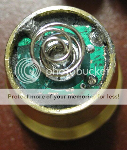
Used one of the sharp screwdriver tips from a Leatherman Wave to gouge out the black epoxy and expose the driver:
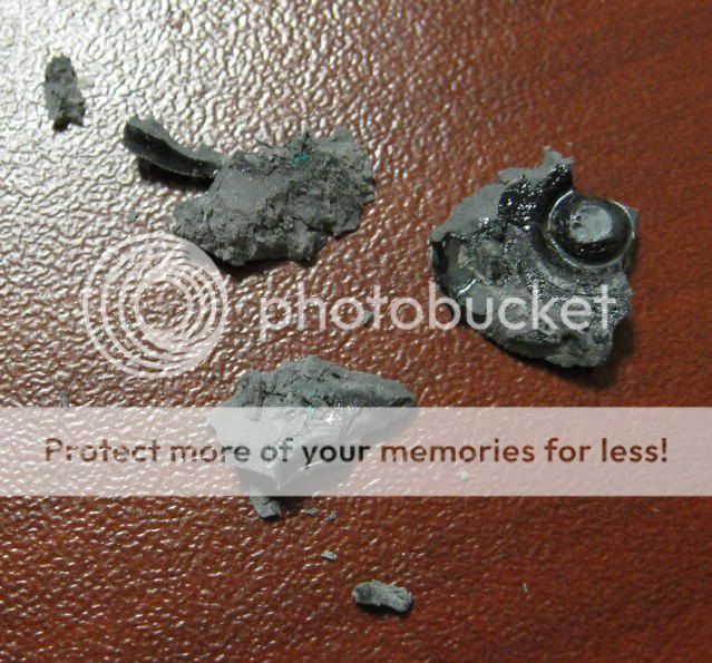
Malkoffdriverexposed.jpg


Epoxy bits:
Malkoffblackepoxy.jpg


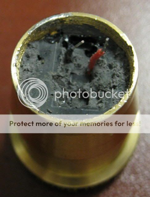
I peeled up the driver. Some components got torn off in the process.
Malkoffdriverpeeledup.jpg


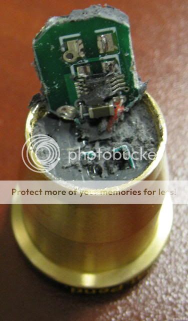
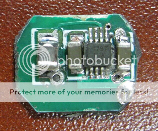
De-soldered the driver from the hookup wire leads. Note the use of a Maxim 1797 boost IC.
Malkoffdriverremoved.jpg


Malkoffboostdriver.jpg


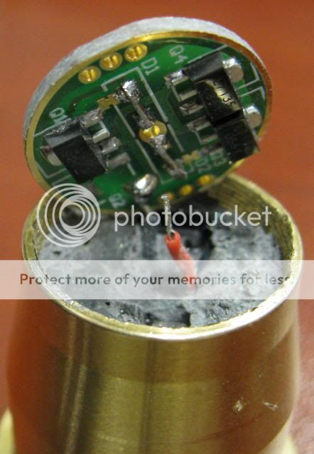
I substituted a single mode, 3xAMC7135 driver. I had to sand down the board to about 16.5mm diameter to fit into the heat sink. In this photo, I soldered only the black wire to the board, so that I could take the photo with the driver angled as seen. When using 1xIMR26500 in an FM IMR-C body, I get 1.06A current draw at the tail.
Malkoff3xAMC7135driver.jpg


FiveMega1xIMR-C.jpg


Beam shot from 6 feet, EV = -2. Hot spot lux at 1 meter ~7000.
Malkoffbeamshot6feetEV-2.jpg
 
Last edited:

Winx

Newly Enlightened
Joined
Mar 20, 2008
Messages
163
Location
Tampere, Finland
Nice. I have been thinking about to modify working M30 with Shiningbeam's 3-mode 1 amp driver. I already made drop-in with that and Q3 5C. Very nice driver, no visible PWM. Although I haven't looked that carefully.
 

greenLED

Flashaholic
Joined
Mar 26, 2004
Messages
13,263
Location
La Tiquicia
Nice job, Justin.
If you heat up the module (boiling in water works) the epoxy will soften up and it's a lot easier to clean out (and not damage the board's components).
 

Justin Case

Flashlight Enthusiast
Joined
Mar 19, 2008
Messages
3,797
Here is an oddity. It looks to me like the Maxim 1797 boost IC's feedback pin (pin #2) is connected to ground, which means that Vout is set to 5V. Not sure why the circuit should be that way. Seems like such a driver circuit might mean that your usual single-die, ~3.5V@1000mA LED would be direct driven all they way up to the 5V limit. Anyone else see it differently?
 

rmteo

Flashlight Enthusiast
Joined
Feb 11, 2009
Messages
1,071
Location
Colorado, USA
Looking at graph #5 on page 6 of the MAXIM datasheet and the description of the M30 on the website should give you a good idea.
 

Justin Case

Flashlight Enthusiast
Joined
Mar 19, 2008
Messages
3,797
Well the M30 web site also says the input voltage is 1V-5.5V, while the 1797 spec says that the IC input voltage range is from 0.7V to Vout, where Vout "can be set from +2V to +5.5V". I don't see any resistor voltage divider network on the driver to achieve Vout of 5.5V. So there is that apparent discrepancy.

As for Graph 5 on P. 6 of the 1797 datasheet compared to the M30 web site specs, I would assume that the LED is getting a nominal 1000mA at 3.3V to achieve 235+ lumens. But Graph 5 suggests only about 700mA or 750mA drive current at that input voltage.
 

Black Rose

Flashlight Enthusiast
Joined
Mar 8, 2008
Messages
4,626
Location
Ottawa, ON, Canada
Nice. I have been thinking about to modify working M30 with Shiningbeam's 3-mode 1 amp driver. I already made drop-in with that and Q3 5C. Very nice driver, no visible PWM. Although I haven't looked that carefully.
Those drivers do not use PWM for the low and medium modes....it's all current controlled :thumbsup:
 

Justin Case

Flashlight Enthusiast
Joined
Mar 19, 2008
Messages
3,797
I'm missing the relevance of Graph 5, P. 5 of the datasheet.

The driver basically looks like it copies the "Typical Operating Circuit" on P. 1, with the major difference that FB goes to GND instead of OUT (which fixes the output voltage at 5.0V). I see only the MAX1797, two caps, and an inductor on the board, just like with the "Typical Operating Circuit". What I would expect is a quasi-direct drive behavior, with graph #5 on P. 6 of the MAX1797 datasheet (specifically, the VOUT=+5.0V curve) convolved with the Vf-If curve of the LED. For example, the VOUT=+5.0V curve in graph #5 on P.6 of the datasheet shows a max output current of slightly more than 600mA (maybe about 630mA) at Vbatt=3.0V. At that forward current, based on jtr1962's data, a Cree XR-E Q5 could have a Vf of about 3.4V.

MrGman measured Iin=0.97A at Vin=3.0V, with Pdriver=2.91W and lumens out of about 157 lumens. That lumens figure is consistent with jtr1962's measurement of about 164 lumens for 600mA forward current. I estimate PLED at 0.630A*3.4V=2.14W, for a driver efficiency of about 74%.

Those who have an M30 and a bench power supply, hook up the M30 and test it from 0V-5.5V. I wager that the result will look like direct drive (see MrGman's data, for example), with the LED overdriven at Vin above about 3.5V (where If should be ~1000mA). As Vin continues to increase above ~3.5V, the forward current will probably eventually max out as the MAX1797 boost IC hits its switch current limit. For example, MrGman measured 1.89A current draw at 5.0V input, for a power draw by the driver of 9.45W. He also measured 269 lumens. Based on the data from jtr1962 in his white lumens testing thread, that might correspond to a forward current of about 1200mA-1400mA and a forward voltage of about 3.6V. This looks like approx the switch current limit for the MAX1797. It also looks like an overdriven LED and a very low driver efficiency (approx 3.6V*1.3A /9.45W = 4.68/9.45 = 50%).
 
Last edited:
Top