Modifying 35w ebay ballast questions

liteitup

Newly Enlightened
Joined
Jul 11, 2004
Messages
163
Hey guys i have these 35w ebay ballasts that i bought before i realized they are no where near the 35w rating. I bought the 55w ballasts which are still not truly 55w but they are atleast putting out what a "normal" 35w hid ballast is. Im quite happy with the output of these 55w ballasts. Needless to say in cpf fashion the 35w dimmer ballasts are now paperweights that are in need of modding.

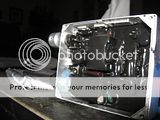
Ive ripped this 35w ballast apart and want to overdrive it. Ive read all kinds of threads here on modifying ballasts. One of the best threads from MorePower looked like it dealt with the 55w version i have. This 35w one is a different design. Appartently modifying the sense resistors on the 55w ballast only changed the start up current. Im wondering if adding resistors to this 35w ballast would on do the same thing? Has anyone played with one of these and can give me a direction to run with? I can solder but really have no idea what each piece in this ballast is or does... here are some internal pictures. click to get full size


thanks!
 

roadie

Enlightened
Joined
Sep 17, 2006
Messages
825
Location
Singapore
i got abit blurred trying to read yr problem ....

kindly state the main issue .. and kindly have a pic of the ballast in its orginal form ... and prove details where u got it ... etc
 

liteitup

Newly Enlightened
Joined
Jul 11, 2004
Messages
163
i got abit blurred trying to read yr problem ....

kindly state the main issue .. and kindly have a pic of the ballast in its orginal form ... and prove details where u got it ... etc

no issues it works, just no where near 35watt. I want to overdrive this ballast and am wondering if anyone has dealt with this particular one. its a 35w from xtreme hids. thanks
 

Patriot

Flashaholic
Joined
Feb 13, 2007
Messages
11,254
Location
Arizona
I understood your question fine I just don't have the knowledge to help you. I would PM Morepower and send him some detailed and sharp pictures of the ballast with insulation removed. Even though it's not the same ballast, he might be able to point you in the right direction.
 

liteitup

Newly Enlightened
Joined
Jul 11, 2004
Messages
163
I understood your question fine I just don't have the knowledge to help you. I would PM Morepower and send him some detailed and sharp pictures of the ballast with insulation removed. Even though it's not the same ballast, he might be able to point you in the right direction.

he hasnt been online since august :(
 

bshanahan14rulz

Flashlight Enthusiast
Joined
Jan 29, 2009
Messages
2,819
Location
Tennessee
look for a bunch of resistors in parallel and hope that they are for adjusting current after warmup.

Looks like they tried to save money by partially potting instead of completely potting? bleh.

But yeah, if the 55W has the same parts layout, you might could find out how. Have you tried doing anything with the other || resistors? the ones that aren't marked "sense resistors"
 

liteitup

Newly Enlightened
Joined
Jul 11, 2004
Messages
163
look for a bunch of resistors in parallel and hope that they are for adjusting current after warmup.

Looks like they tried to save money by partially potting instead of completely potting? bleh.

But yeah, if the 55W has the same parts layout, you might could find out how. Have you tried doing anything with the other || resistors? the ones that aren't marked "sense resistors"

havnt attempted anything yet. dont want to smoke it lol... i think i will try first with the resistors i marked as sense resistors. they are in parallel and im assuming .05 ohms a piece? Like i said i dont know that much about components but im not afraid to learn new things.
 

liteitup

Newly Enlightened
Joined
Jul 11, 2004
Messages
163
Getting more of the potting material off the critical areas is worth the effort.
Here are two resistor charts that might help. I think the ones to look for are in groups of equal value :

http://www.webcalc.net/calc/0231.php
http://www.hobby-hour.com/electronics/resistorcalculator.php

Nice that they went easy on the potting! :thumbsup: Go for it.

the black coating is actually rubber... unfortunately it doesnt really come off easy. The underside with the circuit board was a foam. Im hoping the 3 r050 resistors in parallel are the current sensing resistors. I would add more to make it see less current correct?
 

joedm

Newly Enlightened
Joined
Jun 13, 2006
Messages
161
Location
Australia
might be time for someone to take one for the team and try this out :thumbsup:

I'd definitely be doing something along these lines if someone could figure this out.
 

IgNITEor

Newly Enlightened
Joined
Oct 1, 2006
Messages
193
Location
central Oregon high desert
That's one way to describe it. Decrease resistance, increase current flow.
If you can find a potentiometer/variable resistor with your existing value near it's midpoint, you've got easy flexibility to fine tune things.

Locating all the solder traces and where resistors are bridged is helpful.
You'll eventually want to find room for some heat removal as the board's gonna get cookin' later!
 

liteitup

Newly Enlightened
Joined
Jul 11, 2004
Messages
163
That's one way to describe it. Decrease resistance, increase current flow.
If you can find a potentiometer/variable resistor with your existing value near it's midpoint, you've got easy flexibility to fine tune things.

Locating all the solder traces and where resistors are bridged is helpful.
You'll eventually want to find room for some heat removal as the board's gonna get cookin' later!

i was wrong about the top coating... it is potted with a thin rubber layer. i scraped at it a little harder and it starter coming off.

The three parallel resistors appear to be between a FET and some type of coil (flyback converter on the following link)...


Im trying to follow this thread. It appears that they have a similar setup as far as the resistors, fet, and the coil. https://www.candlepowerforums.com/threads/151030


That particular ballast also has 6 .1 ohm resistors which would have the same value as 3 .05ohm resistors, correct? Im hoping i can just add 2 more resistors to bump the output into the 40w OUTPUT range. Now i just have to source some of these r050 resistors and give it a shot i guess. I guess i could also try to unsolder one of the resistors and see if the output goes down.

Now there is another thread dealing with the 55w rated ballast and adjusting the resistors only changed the startup current. but they also talked about a pot. to adjust but i cant find any pot. on this board...
 
Last edited:

liteitup

Newly Enlightened
Joined
Jul 11, 2004
Messages
163
might be time for someone to take one for the team and try this out :thumbsup:

I'd definitely be doing something along these lines if someone could figure this out.

ill take one for the team, but i dont want to go shooting in the dark either lol!
 

IgNITEor

Newly Enlightened
Joined
Oct 1, 2006
Messages
193
Location
central Oregon high desert
Correct.They're probably using six to dissipate some heat. Interesting that they are having to use six all together in parallel. Hmmmm......
Make notes, you've got a big audience. Like all those people during the Dark Ages up in the galleries watching open room medical operations.

Snip, snip...........:popcorn:
 

LumenHound

Flashlight Enthusiast
Joined
Apr 16, 2005
Messages
1,797
Location
Toronto
I have a "35 watt" spotlight and it's ballast has an almost identical layout. On mine there is a tiny pot on the side of the small board closest to the case. The pot was covered with potting compound and was initially hard to detect due to it's small size.
I had to put a hole in the side of the ballast case in order to get at the compound surrounding the pot with sharp toothpicks.
 

mvyrmnd

Flashlight Enthusiast
Joined
Sep 4, 2009
Messages
3,391
Location
Australia
I have a "35 watt" spotlight and it's ballast has an almost identical layout. On mine there is a tiny pot on the side of the small board closest to the case. The pot was covered with potting compound and was initially hard to detect due to it's small size.
I had to put a hole in the side of the ballast case in order to get at the compound surrounding the pot with sharp toothpicks.
My 35W was similar - after finding the little pot under the rubber and clearing around it, it was just a matter of turning it a little and measuring the output amps.

Mine kept going all the way to .0023 Amps on the bulb side. At 20,000V (average output from ballast, my DMM doesn't go high enough to confirm) thats a tasty 46W from a 35W ballast. It's racked up a few hours at that rate and so far no hassles.
 

joedm

Newly Enlightened
Joined
Jun 13, 2006
Messages
161
Location
Australia
got any pics of this pot?

If you have, it may tempt me to bust mine open and have a look :popcorn:
 

mvyrmnd

Flashlight Enthusiast
Joined
Sep 4, 2009
Messages
3,391
Location
Australia
Check out Morepower's post
https://www.candlepowerforums.com/posts/2581207&postcount=7

The first picture shows the pot. It's tiny ans looks like a raised Philips head screw.

His advice in an earlier post "Anyway 1/4 turn clockwise is all it takes, but don't go any further than that or you will start going backwards as the pot dosn't seem to have a definate stop."

The pot does not have a stop. it will just keep on turning all day. Think of it like a clock. At 11:59 it's at it's highest resistance. at 12:00 it's at it's minimum. You just need to find 12:00. I took the time to turn a little and test, and kept going until I found it.

You can go for the resistor mod that followed in the linked post, but I didn't want to puch much more thatn that on cheap hardware.

Good Luck!
 

bshanahan14rulz

Flashlight Enthusiast
Joined
Jan 29, 2009
Messages
2,819
Location
Tennessee
There are many many ballasts with the "Hella gen3" case. Anybody have any insight as to which one is the kind with the easy-to-mod pot? One user found the pot in the ballast that was already installed in his HID light, but just curious if others have found ballasts from aftermarket sources with the same components.
 

BVH

Flashaholic
Joined
Sep 25, 2004
Messages
7,023
Location
CentCalCoast
just a note on some of the POTs out there. Seems some of us with Xeray ballasts found that the POT's are not geared for much turning of the screw. I know of one who increased from 75 to 80 Watts or so and no matter how many times he tried to bring it back to original position, it would not change output any longer.
 
Top