HKJ
Flashaholic
[size=+3]Drivers, how leds are adapted for different battery voltages[/size]
With incandescent flashlight the battery voltages has to match the bulb voltage, but with a led flashlight this is not the case, instead a electronic circuit is placed between the battery and the led to adjust the battery voltage to the led. In this article I will describe different types of drivers and what voltages/battery configurations they work with.
When adding a electronic circuit to the light, many manufacturers also includes electronic to select different brightness levels in the driver circuit. The brightness can, depending on some factors, be regulated with either PWM (puls width modulation) or CC (current control).
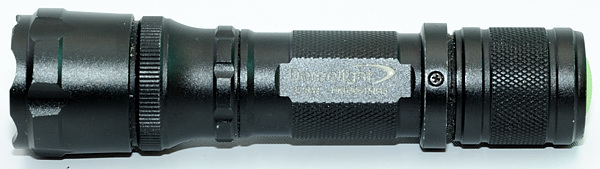
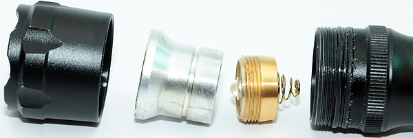
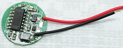
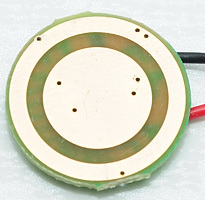
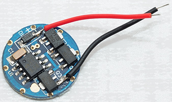
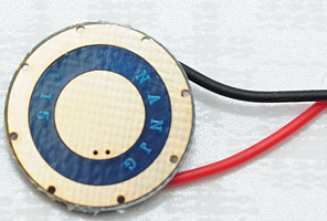
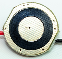
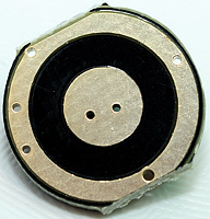
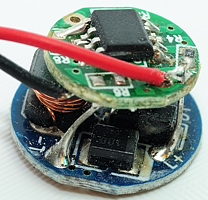
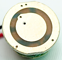
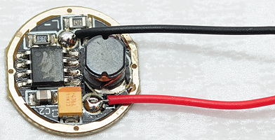
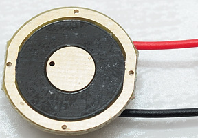
These drives has to be placed in the flashlight, the usual location is in the head of the light, just behind the led. I have used a light where it is possible to remove the led/driver assembly (Called a pill), as an example.
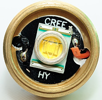
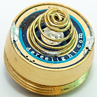
Looking from the led side, it is possible to see the red and black wires from the driver and from the bottom the driver circuit board can be seen.
[size=+2]Voltages[/size]
In the old days with incandescent, the bulb voltage and the battery voltage had to match (Usual bulb voltage a bit less than battery voltage). But with led's it is another game, a led white will turn on at about 2.5 volt, and reach maximum brightness at about 3.7 volt, but this voltage varies between different samples of the same led, the voltage is called Vf. Depending on battery voltage and what kind of regulation is required, different types of drivers has to be used.
The battery voltage will depend on the chemistry of the battery (and number of batteries used):
These voltages are from a fresh battery measured without load to a nearly drained battery measured with load.
Trying to match a number of batteries to the led voltage, it is possible to select between the following drives:
Note: The Vf for green or red leds are very different from white leds.
[size=+2]PWM contra CC[/size]
There are two ways to regulate the brightness on a light, either turning the led on/off at a fast rate (PWM) or reducing the current to the led (CC), both has advantages and disadvantages.
Both types of driver can generate audible noise, this noise is generated by the inductor. The audible noise is not from the buck/boost conversion, that works at frequencies far above the audible range, but from the regulation to keep a constant output.
[size=+3]PWM (Pulse Width Modulation)[/size]
This method of regulation will turn the light on/off at a fast pace, and use the ratio between on and off to regulate the brightness. The following traces are recorded with a light sensor in front of the flashlight.
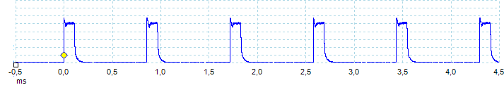
The first trace is from a low level, here the light is on 13% of the time and it is flashing 1200 times each second.
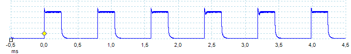
Same light as above, at the medium level, here the light is on 32% of the time and the frequency is the same: 1200 flashes each second.
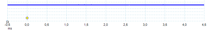
Same light again, this time at full power. Here the flashing is disabled and the light is running at full power all the time.
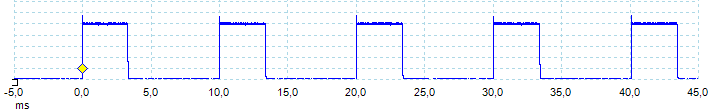
Another light, running at medium power, the light is on 33% of the time, but the frequency is much lower, the light is only flashing 100 times each second. The slow flashing rate has some disadvantages.
In PWM the light is usual driven at full power, but not 100% of the time. This makes it possible to design the driver only for the led Vf at full current, there is no need to handle the lower Vf at lower currents. The constant drive current will also secure that the led tint is stable (It changes slightly with drive current).
But PWM has some serious disadvantages:
A driver working at high current will have lower efficiency, than a driver working at a low current.
A led working at max. current will have lower efficiency than a led with lower current.
The flashing is usual invisible in static situation, but when something is moving, it can play tricks with the vision. One example is something rotating with 6000 RPM that will look like it is standing still or rotating very slowly if the light is supplied from a light with 100 flashes / second. A fan with 3 wings only need to rotate 2000 RPM, because it only need to turn 1/3 turn to look the same.

Here I have sweept the light over a white wall while taking the picture, as expected it shows a line.

But increasing the sweep speed has an unexpected result, only a few spots are bright. This is due to PWM.
[size=+3]CC (Current Control)[/size]
With CC a constant current is always going into the led, to change brightness the current is regulated up or down. Sometimes this regulation might leave a little noise in the current, but this has no visual impact. This noise will make the traces of the light look jagged, the one shown below is very regular, but on some lights it is much more irregular.
The following traces are recorded with a light sensor in front of the flashlight.
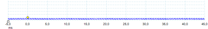
Low brightness, the current is low and stable.
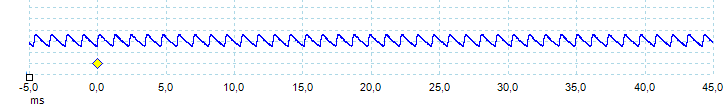
Medium brightness, the regulation is measureable in the light, but not visible to the eye.
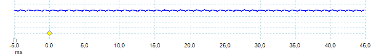
High brightness.
As can be seen, the current is table at all settings. This will give a better efficiency than PWM, because the lower brightness settings is using a lower current and both drive and led has better efficiency at low current (At very low current the efficiency will be worse again).
But CC also has a few disadvantages:
There will be a minor tint shift when changing brightness.
The driver must be able to supply lower voltages to the led, to make low currents possible.
[size=+2]Direct drive[/size]
This is the same way incandescent lights works, the battery is directly connected to the led (There may be small resistor in between). For this to work the battery voltage must be the same or a little bit higher than the led voltage. Looking at the above battery voltages a single LiIon fits the bill, preferable with a small resistor.
Another solution is 3*Alkaline, this is to high a voltage, but alkaline sags under load. Using Lithium FeS2 in this kind of light, will overdrive the led and reduce the lifetime of led, because they do not sag as much as alkaline.
This kind of drive has a very long runtime, because the brightness and current consumption is declining while the power is used. I.e. with a fresh battery the light can have 200 lumen, but after a few hours in can be down to 10 lumen with corresponding much lower power consumption. This is useful for lights that must not just turn off when the battery is low (It does not work with protected LiIon).
Note: The 3xAlkaline solution is used in many cheaper lights.
[size=+3]Examples of direct drive drivers[/size]
Not all direct drive lights are without electronic, this driver here is a direct drive PWM driver, i.e. it will turn the power on/off, but not change any voltage or limit current.
Another direct drive PWM circuit with two modes and strobe.
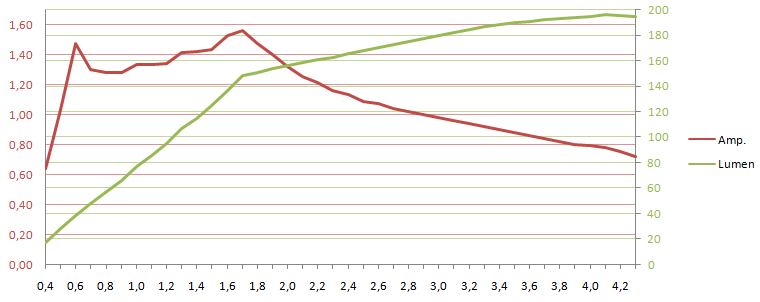
[size=+3]Example curves of the current and brightness[/size]
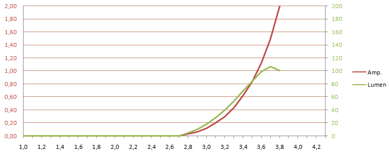
A typical direct drive light. This light is designed to work with 3xAlkaline and depends on the voltage sag in the batteries, to keep the current down. The specification says it is a 3 watt light and it reaches 3 watt at 3.5 volt, but at 3.8 volt it is 7.6 watt and the light output is dropping due to heat.
[size=+3]Battery possibilities when using direct drive[/size]
It is best to stay with exactly the specified battery type, and not change chemistry or battery size.
For other battery size/chemistry, check that the light keeps the same brightnes and does not get hotter than usual.
[size=+2]Current drive[/size]
To make direct drive safer and maybe add some levels to it a constant current generator can be added in series with the battery. This is usual a chip called 7135 that can deliver 350 mA with a very low voltage drop (0.2 volt), using 3 of these will give a 1050 mA drive current (usual rounded to 1000mA).
Due to the 0.2 volt drop in the chip, the battery voltage must be 0.2 volt higher than the led voltage, but the led will not be overdriven, if the voltage is higher. The only problem for higher voltage will be heat in the driver.
This driver works well for a single LiIon and can also be used for 3*alkaline/3*Lithium FeS2.
Drivers with this chip usual include a microprocessor that can be used to turn the chip on/off very fast (PWM) to regulate the brightness of the light.
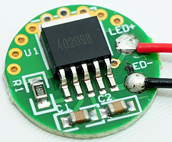
[size=+3]Examples of a current driver[/size]
The picture shows a driver with 3 x 7135 chips and one microprocessor to control the brightness.
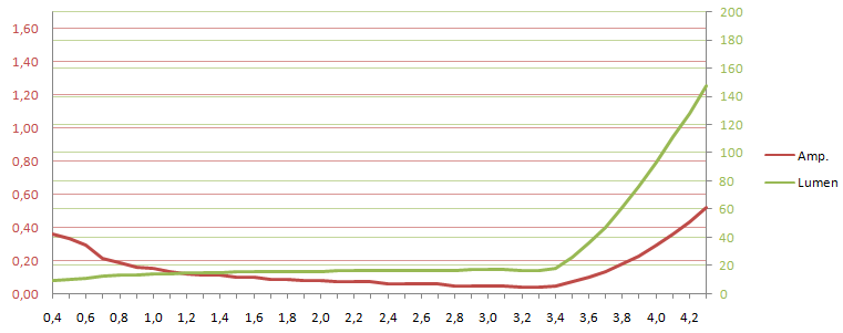
[size=+3]Example curves of the current and brightness[/size]
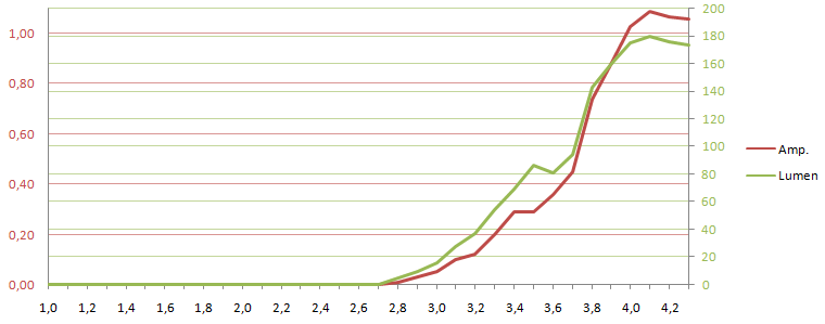
This light has current drive and uses a led that start at a low voltage. The difference between current drive and direct drive is very obvious here, the current stops rising at about 4 volt and stays just above 1A, i.e. 3x7135 chips. The slightly falling output is due to heat.
[size=+3]Battery possibilities when using a current driver[/size]
Use batteries with a voltage slight above the Vf of the led, i.e. 3xAlkaline/NiMH/Lithium FeS2 or 1xLiIon will all work and be safe.
[size=+2]Boost driver[/size]
This type of drive will increase voltage and is used for battery configuration with below led voltage. If the battery voltage is above the led voltage, the current will usual pass through the driver (with a small voltage loss) and directly drive the light at higher than maximum brightness.
This makes boost driver useful for many different battery configurations:
Note: Some drives are only designed to work with voltages in the 1 to 1.5 volt range.
Because the drive can only increase voltage, it might have some problems with low brightness settings, when using batteries with more than 3 volt, but that depends on how the brightness is regulated: PWM: No problem, CC: low brightness is not low anymore.
These drivers will require a high (Usual about 1 volt) voltage to start and when started they can sustain a considerable lower battery voltage.
[size=+3]Examples of boost driver[/size]
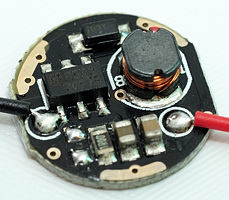
A 0.5 A boost driver with 0.7 to 3.0 volt input range, it has only a single brightness level.
A more powerful boost driver, this driver can deliver 1 A with 0.7 to 4.2 volt input, it has only a single brightness level.
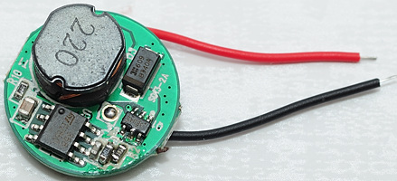
A boost driver with 5 modes, to get space for a microprocessor a second level has been added. This is sometimes done by using a boost controller to feed a direct drive controller (Note the L+ and L- legend on the lower circuit, this is probably LED+ and LED-).
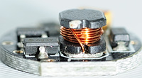
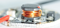
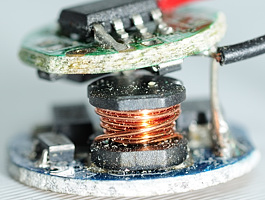
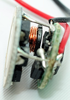
All drivers has an inductor (the coil with copper wire), this shows that it is a buck or boost driver.
[size=+3]Example curves of the current and brightness[/size]
First a boost driver running at maximum output, at low voltage it is limited by a maximal current draw of about 1.4A, when the voltage reaches 1.7 volt the light will try to keep a stable output, but is not perfect at it. The driver must have a high voltage drop or the led a high Vf, because it keeps a steady dropping current up to 4.3 volt.
This light is "safe" with LiIon, the power is staying at about 3 watt.
Same light, this time on low. Here the light reaches a stable output below 1 volt, but when the battery voltages reaches 3.5 volt the current and brightness will increase, this is because leds has a lower Vf at lower output and when the battery is above the Vf + driver loss for the low setting, the circuit goes into direct drive with no control of brightness or current. But it looks safe enough, because it does not go above the maximum output from the previous graph.
Another light with better regulation, up to about 1.8 volt the light is current limited, and then it keeps good regulation, until it goes into direct drive at 3.8 volt. This light may be damaged by LiIon batteries, because the led power is considerable increased (doubled) above the designed level. At the specified voltages it uses about 3 watt, but with a fresh LiIon it will use 6-7 watt.
A very classical boost driver, it is easy to see the different phases of the regulation:
1) Below 1.4 volt the driver can not draw maximum current.
2) From 1.4 to 2.3 volt the driver is limited by current, this limit is placed at about 2.2 A for this driver.
3) From 2.3 volt to 3.7 volt the driver has good regulation.
4) Above 3.7 volt the driver goes into direct drive and the current will increase fast.
Another type of boost driver, this driver keeps a constant current load on the battery and will increase the power to the led with increasing battery voltage. The drive looks safe up to about 3 volt, above that the led does not increase much in brightness, even with increasing power consumption, this is probably because the efficiency of the led is dropping due to temperature. At 3.6 volt the driver goes into direct drive and the led output goes dramatically down, this is a very bad sign.
[size=+3]Battery possibilities when using a boost driver[/size]
Do not use a battery with more volts than the light is specified for, LiIon can be very hard on this kind of light (or work fine).
A light rated for 3 volt (Lithium or 2xAlkaline/NiMH/Lithium FeS2) might also work at 1.5 volt (i.e. 1xAlkaline/NiMH/Lithium FeS2).
Many people do use LiIon in these lights and often it will work, but the lifetime of both the led and the battery will be greatly reduced, if the drive power goes significantly up.
[size=+2]Buck driver[/size]
This type of drive will decrease voltage and is used for battery configuration with above led voltage. If the battery voltage is below the led voltage, the current will usual pass through the driver (with a small voltage loss) and directly drive the light at lower brightness.
This makes this driver useful for many different battery configurations:
Note: Drivers has a maximum voltage they can stand, this is seldom specified but will usual be above 9 volt (i.e. 2xLiIon).
Because this driver can only decrease voltage, it has a problem with 1xLiIon, the minimum LiIon voltage is below what is required for maximum brightness in a led (3.7 volt). A led with a low Vf and a driver with a low voltage drop can just about keep a stable output on LiIon.
Using CC for brightness will always work and allow the full range of brightness settings.
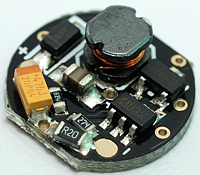
[size=+3]Examples of buck driver[/size]
The above picture shows a single level buck driver.
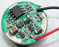
This picture shows a multilevel buck driver. Because there is electronic for both buck and brightness control, the circuit contains many parts and requires both sides of the circuit board (In some lights 2 or 3 circuit boards are stacked).
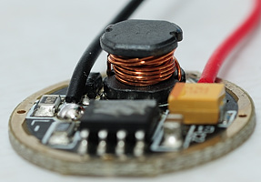
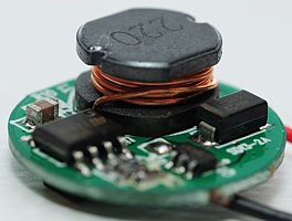
Both drivers has an inductor (the coil with copper wire), this shows that it is a buck or boost driver.
[size=+3]Example curves of the current and brightness[/size]
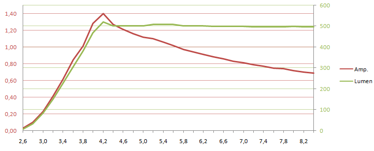
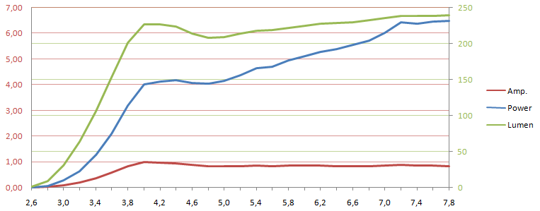
Here is a typical buck driver, the brightness and current will increase until the voltage reaches 4.2 volt (That is Vf and driver loss), then the brightness stabilizes and the current will drop with increasing voltage.
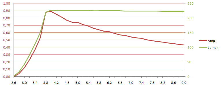
Another typical buck driver, here the changeover is at about 3.8 volt
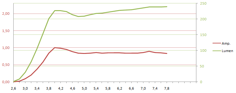
This driver was a bit of a surprise, the current increases until 4 volt, then the brightness stabilizes and the current starts dropping, but at around 5 volt the current does not drop anymore, but stays constant.
[size=+3]Battery possibilities when using a buck driver[/size]
Many lights designed for 2xCR123 will work with a single LiIon battery, either 17670 (for a battery tube with low inner diameter) or 18650, but the light output is not fully stabilized.
For 3xCR123 lights it is safe to use 2x17500 or 2x18500 LiIon batteries, it is just about the same voltage, but it might not be safe to use 3x16340 LiIon batteries.
On 2xCR123 light the batteries can often be replaced with 2x16340 LiIon batteries, many buck drivers can take the extra voltage, but this will cut the runtime in half. Check the current draw with CR123 and 16340 batteries, the 16340 must draw less current than CR123 (With fresh batteries 20-30% less current is expected).
[size=+2]Buck/boost driver[/size]
This type of drive will either increase or decrease voltage, depending on what is required. This makes it the best driver for multiple battery configurations and for light that can do both full brightness and a really low low with a supply in the 3 to 4 volt range without using PWM.
This driver is often used on single cell LiIon lights, that both have a high and very low brightness. The driver can boost the voltage from a nearly empty LiIon to the full Vf of the led at max. brightness, but it can also buck the voltage from a full LiIon to the low Vf of a low brightness CC driven led.
[size=+3]Example curves of the current and brightness[/size]
This driver works from 0.9 to 4.2 volts, it looks like any boost driver at low voltages, but due to the buck function, it does not increase current or brightness in the 3.7 to 4.3 volt range.
Same light, this time on low level, as can be seen the driver has no problem keeping a low level independent of the battery voltage.
[size=+3]Battery possibilities when using a buck/boost driver[/size]
The reason to use buck/boost driver is to support batteries with voltage both below and above the Vf of the led, i.e. these light will support 2xAlkaline/NiMH/Lithium FeS2, 1xCR123 and 1x16340 batteries with full brightness control for both types.
They might also support lower voltages and it is safe to try batteries with lower voltages.
Do not use higher voltages, except if it is specified.
[size=+2]Notes[/size]
All voltages in here are rough values, different led voltages (Vf) and different driver architecture will have slightly different voltages.
All lumen values are scaled from lux measurement and lumen specification of flashlight.
Discharging a LiIon battery too much, can make it unsafe, be careful with unprotected LiIon batteries!
It is never completely safe to go outside the specification for a battery or flashlight, sometimes a light or a battery might get damaged or blow up, following the guidelines here will keep this risk at a minimum, but not eliminate it completely.
I usual writes 16340 to specify 3.7 volt LiIon batteries in CR123 size, because RCR123 can also mean 3.2 volt LiIon batteries.
With incandescent flashlight the battery voltages has to match the bulb voltage, but with a led flashlight this is not the case, instead a electronic circuit is placed between the battery and the led to adjust the battery voltage to the led. In this article I will describe different types of drivers and what voltages/battery configurations they work with.
When adding a electronic circuit to the light, many manufacturers also includes electronic to select different brightness levels in the driver circuit. The brightness can, depending on some factors, be regulated with either PWM (puls width modulation) or CC (current control).
These drives has to be placed in the flashlight, the usual location is in the head of the light, just behind the led. I have used a light where it is possible to remove the led/driver assembly (Called a pill), as an example.
Looking from the led side, it is possible to see the red and black wires from the driver and from the bottom the driver circuit board can be seen.
[size=+2]Voltages[/size]
In the old days with incandescent, the bulb voltage and the battery voltage had to match (Usual bulb voltage a bit less than battery voltage). But with led's it is another game, a led white will turn on at about 2.5 volt, and reach maximum brightness at about 3.7 volt, but this voltage varies between different samples of the same led, the voltage is called Vf. Depending on battery voltage and what kind of regulation is required, different types of drivers has to be used.
The battery voltage will depend on the chemistry of the battery (and number of batteries used):
- Alkaline: 0.8 to 1.5 volt
- NiMH: 1 to 1.4 volt
- Lithium FeS2: 0.8 to 1.7 volt
- Lithium: 2 to 3 volt
- LiIon: 3.3 to 4.2 volt
These voltages are from a fresh battery measured without load to a nearly drained battery measured with load.
Trying to match a number of batteries to the led voltage, it is possible to select between the following drives:
- With voltage below the led voltage a boost driver must be used.
- When the battery voltage is just above the led voltage, it is possible to use direct drive or a current driver.
- With voltage significantly above the led voltage a buck drive is used.
- With the battery voltage both below and above the led voltage a buck/boost driver is used.
Note: The Vf for green or red leds are very different from white leds.
[size=+2]PWM contra CC[/size]
There are two ways to regulate the brightness on a light, either turning the led on/off at a fast rate (PWM) or reducing the current to the led (CC), both has advantages and disadvantages.
Both types of driver can generate audible noise, this noise is generated by the inductor. The audible noise is not from the buck/boost conversion, that works at frequencies far above the audible range, but from the regulation to keep a constant output.
[size=+3]PWM (Pulse Width Modulation)[/size]
This method of regulation will turn the light on/off at a fast pace, and use the ratio between on and off to regulate the brightness. The following traces are recorded with a light sensor in front of the flashlight.
The first trace is from a low level, here the light is on 13% of the time and it is flashing 1200 times each second.
Same light as above, at the medium level, here the light is on 32% of the time and the frequency is the same: 1200 flashes each second.
Same light again, this time at full power. Here the flashing is disabled and the light is running at full power all the time.
Another light, running at medium power, the light is on 33% of the time, but the frequency is much lower, the light is only flashing 100 times each second. The slow flashing rate has some disadvantages.
In PWM the light is usual driven at full power, but not 100% of the time. This makes it possible to design the driver only for the led Vf at full current, there is no need to handle the lower Vf at lower currents. The constant drive current will also secure that the led tint is stable (It changes slightly with drive current).
But PWM has some serious disadvantages:
A driver working at high current will have lower efficiency, than a driver working at a low current.
A led working at max. current will have lower efficiency than a led with lower current.
The flashing is usual invisible in static situation, but when something is moving, it can play tricks with the vision. One example is something rotating with 6000 RPM that will look like it is standing still or rotating very slowly if the light is supplied from a light with 100 flashes / second. A fan with 3 wings only need to rotate 2000 RPM, because it only need to turn 1/3 turn to look the same.
Here I have sweept the light over a white wall while taking the picture, as expected it shows a line.
But increasing the sweep speed has an unexpected result, only a few spots are bright. This is due to PWM.
[size=+3]CC (Current Control)[/size]
With CC a constant current is always going into the led, to change brightness the current is regulated up or down. Sometimes this regulation might leave a little noise in the current, but this has no visual impact. This noise will make the traces of the light look jagged, the one shown below is very regular, but on some lights it is much more irregular.
The following traces are recorded with a light sensor in front of the flashlight.
Low brightness, the current is low and stable.
Medium brightness, the regulation is measureable in the light, but not visible to the eye.
High brightness.
As can be seen, the current is table at all settings. This will give a better efficiency than PWM, because the lower brightness settings is using a lower current and both drive and led has better efficiency at low current (At very low current the efficiency will be worse again).
But CC also has a few disadvantages:
There will be a minor tint shift when changing brightness.
The driver must be able to supply lower voltages to the led, to make low currents possible.
[size=+2]Direct drive[/size]
This is the same way incandescent lights works, the battery is directly connected to the led (There may be small resistor in between). For this to work the battery voltage must be the same or a little bit higher than the led voltage. Looking at the above battery voltages a single LiIon fits the bill, preferable with a small resistor.
Another solution is 3*Alkaline, this is to high a voltage, but alkaline sags under load. Using Lithium FeS2 in this kind of light, will overdrive the led and reduce the lifetime of led, because they do not sag as much as alkaline.
This kind of drive has a very long runtime, because the brightness and current consumption is declining while the power is used. I.e. with a fresh battery the light can have 200 lumen, but after a few hours in can be down to 10 lumen with corresponding much lower power consumption. This is useful for lights that must not just turn off when the battery is low (It does not work with protected LiIon).
Note: The 3xAlkaline solution is used in many cheaper lights.
[size=+3]Examples of direct drive drivers[/size]
Not all direct drive lights are without electronic, this driver here is a direct drive PWM driver, i.e. it will turn the power on/off, but not change any voltage or limit current.
Another direct drive PWM circuit with two modes and strobe.
[size=+3]Example curves of the current and brightness[/size]
A typical direct drive light. This light is designed to work with 3xAlkaline and depends on the voltage sag in the batteries, to keep the current down. The specification says it is a 3 watt light and it reaches 3 watt at 3.5 volt, but at 3.8 volt it is 7.6 watt and the light output is dropping due to heat.
[size=+3]Battery possibilities when using direct drive[/size]
It is best to stay with exactly the specified battery type, and not change chemistry or battery size.
For other battery size/chemistry, check that the light keeps the same brightnes and does not get hotter than usual.
[size=+2]Current drive[/size]
To make direct drive safer and maybe add some levels to it a constant current generator can be added in series with the battery. This is usual a chip called 7135 that can deliver 350 mA with a very low voltage drop (0.2 volt), using 3 of these will give a 1050 mA drive current (usual rounded to 1000mA).
Due to the 0.2 volt drop in the chip, the battery voltage must be 0.2 volt higher than the led voltage, but the led will not be overdriven, if the voltage is higher. The only problem for higher voltage will be heat in the driver.
This driver works well for a single LiIon and can also be used for 3*alkaline/3*Lithium FeS2.
Drivers with this chip usual include a microprocessor that can be used to turn the chip on/off very fast (PWM) to regulate the brightness of the light.
[size=+3]Examples of a current driver[/size]
The picture shows a driver with 3 x 7135 chips and one microprocessor to control the brightness.
[size=+3]Example curves of the current and brightness[/size]
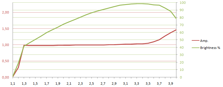
This light has current drive and uses a led that start at a low voltage. The difference between current drive and direct drive is very obvious here, the current stops rising at about 4 volt and stays just above 1A, i.e. 3x7135 chips. The slightly falling output is due to heat.
[size=+3]Battery possibilities when using a current driver[/size]
Use batteries with a voltage slight above the Vf of the led, i.e. 3xAlkaline/NiMH/Lithium FeS2 or 1xLiIon will all work and be safe.
[size=+2]Boost driver[/size]
This type of drive will increase voltage and is used for battery configuration with below led voltage. If the battery voltage is above the led voltage, the current will usual pass through the driver (with a small voltage loss) and directly drive the light at higher than maximum brightness.
This makes boost driver useful for many different battery configurations:
- 1xAlkaline/NiMH/Lithium FeS2
- 2xAlkaline/NiMH/Lithium FeS2
- 1xLithium
- And sometimes: 1xLiIon
Note: Some drives are only designed to work with voltages in the 1 to 1.5 volt range.
Because the drive can only increase voltage, it might have some problems with low brightness settings, when using batteries with more than 3 volt, but that depends on how the brightness is regulated: PWM: No problem, CC: low brightness is not low anymore.
These drivers will require a high (Usual about 1 volt) voltage to start and when started they can sustain a considerable lower battery voltage.
[size=+3]Examples of boost driver[/size]
A 0.5 A boost driver with 0.7 to 3.0 volt input range, it has only a single brightness level.
A more powerful boost driver, this driver can deliver 1 A with 0.7 to 4.2 volt input, it has only a single brightness level.
A boost driver with 5 modes, to get space for a microprocessor a second level has been added. This is sometimes done by using a boost controller to feed a direct drive controller (Note the L+ and L- legend on the lower circuit, this is probably LED+ and LED-).
All drivers has an inductor (the coil with copper wire), this shows that it is a buck or boost driver.
[size=+3]Example curves of the current and brightness[/size]
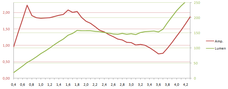
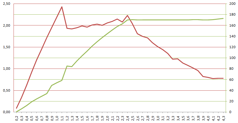
First a boost driver running at maximum output, at low voltage it is limited by a maximal current draw of about 1.4A, when the voltage reaches 1.7 volt the light will try to keep a stable output, but is not perfect at it. The driver must have a high voltage drop or the led a high Vf, because it keeps a steady dropping current up to 4.3 volt.
This light is "safe" with LiIon, the power is staying at about 3 watt.
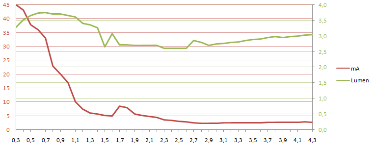
Same light, this time on low. Here the light reaches a stable output below 1 volt, but when the battery voltages reaches 3.5 volt the current and brightness will increase, this is because leds has a lower Vf at lower output and when the battery is above the Vf + driver loss for the low setting, the circuit goes into direct drive with no control of brightness or current. But it looks safe enough, because it does not go above the maximum output from the previous graph.
Another light with better regulation, up to about 1.8 volt the light is current limited, and then it keeps good regulation, until it goes into direct drive at 3.8 volt. This light may be damaged by LiIon batteries, because the led power is considerable increased (doubled) above the designed level. At the specified voltages it uses about 3 watt, but with a fresh LiIon it will use 6-7 watt.
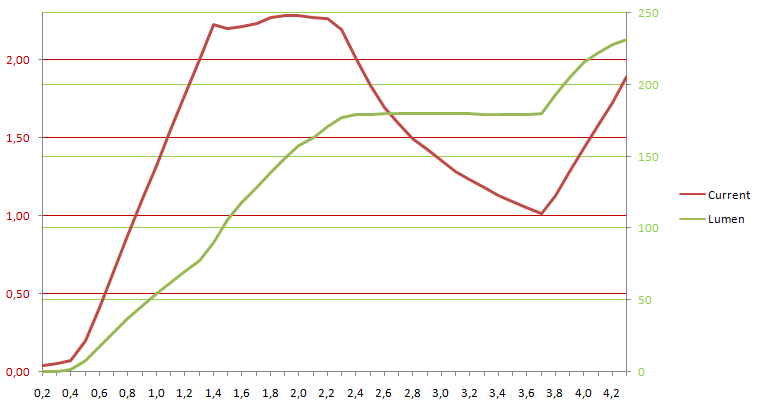
A very classical boost driver, it is easy to see the different phases of the regulation:
1) Below 1.4 volt the driver can not draw maximum current.
2) From 1.4 to 2.3 volt the driver is limited by current, this limit is placed at about 2.2 A for this driver.
3) From 2.3 volt to 3.7 volt the driver has good regulation.
4) Above 3.7 volt the driver goes into direct drive and the current will increase fast.
Another type of boost driver, this driver keeps a constant current load on the battery and will increase the power to the led with increasing battery voltage. The drive looks safe up to about 3 volt, above that the led does not increase much in brightness, even with increasing power consumption, this is probably because the efficiency of the led is dropping due to temperature. At 3.6 volt the driver goes into direct drive and the led output goes dramatically down, this is a very bad sign.
[size=+3]Battery possibilities when using a boost driver[/size]
Do not use a battery with more volts than the light is specified for, LiIon can be very hard on this kind of light (or work fine).
A light rated for 3 volt (Lithium or 2xAlkaline/NiMH/Lithium FeS2) might also work at 1.5 volt (i.e. 1xAlkaline/NiMH/Lithium FeS2).
Many people do use LiIon in these lights and often it will work, but the lifetime of both the led and the battery will be greatly reduced, if the drive power goes significantly up.
[size=+2]Buck driver[/size]
This type of drive will decrease voltage and is used for battery configuration with above led voltage. If the battery voltage is below the led voltage, the current will usual pass through the driver (with a small voltage loss) and directly drive the light at lower brightness.
This makes this driver useful for many different battery configurations:
- 4+xAlkaline/NiMH/Lithium FeS2
- 2+xLithium
- Sometimes 1xLiIon
- 2+xLiIon
Note: Drivers has a maximum voltage they can stand, this is seldom specified but will usual be above 9 volt (i.e. 2xLiIon).
Because this driver can only decrease voltage, it has a problem with 1xLiIon, the minimum LiIon voltage is below what is required for maximum brightness in a led (3.7 volt). A led with a low Vf and a driver with a low voltage drop can just about keep a stable output on LiIon.
Using CC for brightness will always work and allow the full range of brightness settings.
[size=+3]Examples of buck driver[/size]
The above picture shows a single level buck driver.
This picture shows a multilevel buck driver. Because there is electronic for both buck and brightness control, the circuit contains many parts and requires both sides of the circuit board (In some lights 2 or 3 circuit boards are stacked).
Both drivers has an inductor (the coil with copper wire), this shows that it is a buck or boost driver.
[size=+3]Example curves of the current and brightness[/size]
Here is a typical buck driver, the brightness and current will increase until the voltage reaches 4.2 volt (That is Vf and driver loss), then the brightness stabilizes and the current will drop with increasing voltage.
Another typical buck driver, here the changeover is at about 3.8 volt
This driver was a bit of a surprise, the current increases until 4 volt, then the brightness stabilizes and the current starts dropping, but at around 5 volt the current does not drop anymore, but stays constant.
[size=+3]Battery possibilities when using a buck driver[/size]
Many lights designed for 2xCR123 will work with a single LiIon battery, either 17670 (for a battery tube with low inner diameter) or 18650, but the light output is not fully stabilized.
For 3xCR123 lights it is safe to use 2x17500 or 2x18500 LiIon batteries, it is just about the same voltage, but it might not be safe to use 3x16340 LiIon batteries.
On 2xCR123 light the batteries can often be replaced with 2x16340 LiIon batteries, many buck drivers can take the extra voltage, but this will cut the runtime in half. Check the current draw with CR123 and 16340 batteries, the 16340 must draw less current than CR123 (With fresh batteries 20-30% less current is expected).
[size=+2]Buck/boost driver[/size]
This type of drive will either increase or decrease voltage, depending on what is required. This makes it the best driver for multiple battery configurations and for light that can do both full brightness and a really low low with a supply in the 3 to 4 volt range without using PWM.
This driver is often used on single cell LiIon lights, that both have a high and very low brightness. The driver can boost the voltage from a nearly empty LiIon to the full Vf of the led at max. brightness, but it can also buck the voltage from a full LiIon to the low Vf of a low brightness CC driven led.
[size=+3]Example curves of the current and brightness[/size]
This driver works from 0.9 to 4.2 volts, it looks like any boost driver at low voltages, but due to the buck function, it does not increase current or brightness in the 3.7 to 4.3 volt range.
Same light, this time on low level, as can be seen the driver has no problem keeping a low level independent of the battery voltage.
[size=+3]Battery possibilities when using a buck/boost driver[/size]
The reason to use buck/boost driver is to support batteries with voltage both below and above the Vf of the led, i.e. these light will support 2xAlkaline/NiMH/Lithium FeS2, 1xCR123 and 1x16340 batteries with full brightness control for both types.
They might also support lower voltages and it is safe to try batteries with lower voltages.
Do not use higher voltages, except if it is specified.
[size=+2]Notes[/size]
All voltages in here are rough values, different led voltages (Vf) and different driver architecture will have slightly different voltages.
All lumen values are scaled from lux measurement and lumen specification of flashlight.
Discharging a LiIon battery too much, can make it unsafe, be careful with unprotected LiIon batteries!
It is never completely safe to go outside the specification for a battery or flashlight, sometimes a light or a battery might get damaged or blow up, following the guidelines here will keep this risk at a minimum, but not eliminate it completely.
I usual writes 16340 to specify 3.7 volt LiIon batteries in CR123 size, because RCR123 can also mean 3.2 volt LiIon batteries.
Last edited: