P7 Mag Mod (Incomplete and still procrastinating)

Umibuta

Newly Enlightened
Joined
Jul 3, 2009
Messages
48
I have asked too many questions without giving back and my conscience is eating me. So here is my build so far...

Here are the criteria for my build:
- Handy (Mag D is acceptable)
- powerful for video (P7 "seems" ok)
- not much machining required. (I only have a hobby drill and hand tools)

Work required :
- Seals and waterproofing:
1) Epoxy Putty for lens (see pic)
2) UK SL4 O-ring used for tail-cap o-ring
3) off-the-shelf o-ring for the bezel
4) JB weld for piezo and cut-down barrel.

- Light and control
5) heatsink from local PC shop (See pic)
6) SSC P7 CSXO and D Li-ION from KD
7) SKU 07612 from DX for control
8) SKU 01886 from DX to supply up to 2.4A (after 4months of waiting it is being delivered as of this post)

- Switch
9) 16mm Piezo (See pic)
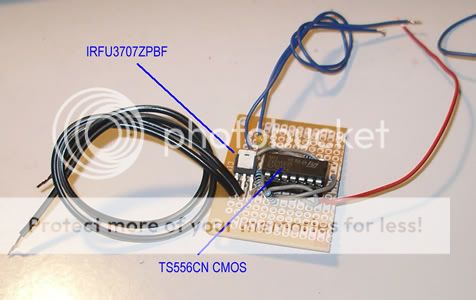
10) using a modified Bill Bowden toggle circuit. (Having difficulties here now)

And here is the work so far since June.....

Bezel.jpg

Putty Epoxy is used to seal the lens to the bezel.

Lens.jpg

Lens is a 4.5mm thick Acrylic (3.5mm at the edge for better thread on bezel)

Contacts.jpg

The switch is on the tail cap. And this screw-in contact is what i came up with. Springs and contacts salvaged from the stock Mag switch. Separate alu. plate was filed to fit tailcap.

Contacts2.jpg

Contacts on tail cap and barrel. Barrel contact plate was tedious to file to fit the tiny step inside the barrel without falling through.

LEDHead.jpg

LED on Heatsink on barrel on Lighthead....

LEDHS1.jpg

Used a heatsink I bought from the local PC shop and filed to size.

Tailcap.jpg

Piezo switch on Tailcap.
 
Last edited:

Umibuta

Newly Enlightened
Joined
Jul 3, 2009
Messages
48
I had wanted to use this circuit by SoCalSwami but this circuit only works above 5V.

7-Bill-Bowden-Inverter-circuit-revised.jpg


I was advised to replace the 556 chip with a CMOS 556 one. Does anyone know if a direct swap of the 556 chip will work or do i need to modify the circuit further for the swap.
 

gcbryan

Flashlight Enthusiast
Joined
Oct 19, 2009
Messages
2,473
Location
Seattle,WA
Is putty epoxy easy to use, how exactly does it work? Meaning, can you use it like regular putty and when it sets is it really hard like regular epoxy or does it still have some flex?

Is it available at some place like Home Depot?

Thanks for the pictures. Sorry I can't answer your question.:confused:
 
Last edited:

H20doctor

Enlightened
Joined
Jan 16, 2008
Messages
222
Location
seattle
your Mag build looks good .... you've got a lot of Hours into that Light , Keep going...
 
Joined
Feb 1, 2008
Messages
889
Location
US
I have some time ago made two PCB for that circuit . If it is in any help for you . Circular version go in the scubapro scubalux 200 (removed battery pack and instaled cylindrical single ended balast 24W(110mm ) and scubapro scubalux 100( removed battery pack and instaled rectangular single ended balast 24W (84mm)) PCB are not super small or even SMT because there were no need to be.


switch it is placed on lower pad (M,M) and version

switch it is placed on the top ( M,M )

I hve used TLC556CN instead of piezo I used reed switch.
 
Last edited:

Umibuta

Newly Enlightened
Joined
Jul 3, 2009
Messages
48
Is putty epoxy easy to use, how exactly does it work? Meaning, can you use it like regular putty and when it sets is it really hard like regular epoxy or does it still have some flex?

Is it available at some place like Home Depot?

Thanks for the pictures. Sorry I can't answer your question.:confused:

I am using the Loctite Fixmaster Underwater Repair Epoxy. Its a 2 part epoxy and is like plasticine when kneaded except that it is stickier. I am not sure if it flex but when hardens you can't leave any nail marks if you dig your nail in. Alternatively, Selleys Knead it Aqua was also recommended to me before. There are no Home Depot where I am so I can't help you with that.

What is your wanted supply voltage? And are you replacing the 556 or the NTE978 chip?

I am using a single Li-LION. That's up to 4.2V. Not sure of the voltage when it is drained. Yes I am replacing the NTE978 for a CMOS 556. Can you help with the circuit (so that it works for a single Li-ION Battery)? :hairpull:Thanks
 

Umibuta

Newly Enlightened
Joined
Jul 3, 2009
Messages
48
I have some time ago made two PCB for that circuit . If it is in any help for you

Lucca> Thank you for the circuit, I still dare not venture into etching my own circuit board yet though I am sure they will be a lot neater. I am sure once I have this torch done I will try building my circuits to make it more compact.

I am not familiar with Electronics but your circuit looks similar to a toggle circuit. Is that the general configuration with circuits involving 556/555 timer?

Btw what is the voltage you are using for your light?
 
Joined
Feb 1, 2008
Messages
889
Location
US
Hi!
I use normaly for my lights (in that case HID 10 cell NiMh , D size) votage at full baterry is arround 15 volts and then drops) at that circuit starts at
2V and up to 15V http://focus.ti.com/lit/ds/symlink/tlc556.pdf piezo can be in that case problematic not TLC556 (it is CMOS).

My circut it is from web page of Bill Bowden .Circuit is modified on MOSFET http://www.bowdenshobbycircuits.info/page9.htm#555mono.gif from relay and it is titled ''Relay Toggle Circuit Using a 556 Timer '' On that page you have similar cirsuits involving timers.

555 IC is a single timer , 556 IC it is a dual timer .
 

Umibuta

Newly Enlightened
Joined
Jul 3, 2009
Messages
48
SealFailure.jpg


Tested the torch yesterday to a depth of over 50m. And the Loctite underwater epoxy gave way at approx 45m. Droplets of water were seen on the edges of the lens. And at 50m a steady stream of tiny bubbles could be seen. Once on the surface the lens could easily be pushed out of the bezel.

Fortunately, I only tested the mag integrity without the internals. This test at least proved that the SL4 o-ring for the tailcap and ,SURPRISINGLY, the stock o-ring for the bezel proved worthy to a depth of 50m. The stepped acrylic lens with the thinnest at approx 3.5mm was also strong enough to with stand the pressure. Overall, I am glad with the results and came out a little more knowledgeable. Hopefully those who are in the same shoes will find this information helpful.

Next test on the lens seal will be with the loctite 5699 flange sealant... hopefully late this month or early february.

Also, the replaced the 556 timer with a cmos 556 and the bowden toggle circuit is working without any fault. With a single Li-ion battery no heat was noticed on the Mosfet as some reported. However, the piezo switched seems to be a little too sensitive switching on and off in a split second from a single touch. Not sure if this is due to the so called "bouncing".
 
Last edited:

hanachan

Newly Enlightened
Joined
Nov 21, 2008
Messages
115
Location
Japan
hi,
your report is very interesting & useful for me.
ive learned more from non success story.

IMHO, the front lens 4.5-3.5mm thick is too thin.
indeed the acrylic lens was not broken but at such depth
it is deformed with water pressure, its central part is dented
and possibly the edge part is warped, that causes seal breaking.
from my experience a (about)10mm thick acrylic plate or (about)6mm thick glass lens
may be necessary to overcome 50m water pressure.

i hope your working's success. Thank you.
 

Packhorse

Flashlight Enthusiast
Joined
Nov 29, 2007
Messages
1,912
Location
New Zealand
I have never used a step lens design in any of my Mag based light builds.
I found the stock Mag polycarbonate ( 1mm+-) deformed enough at 40 meters to smash a MR16 halogen 's lens
Since then I have used 4mm acrylic and had no issues what so ever with regular dives below 50 meters. ( with 8 -10 builds)

In my mind a stepped lens may be stronger and on paper offer a better way of sealing since the O ring is behind the lens but in practice getting the O ring to seal on the thin edge of the light head and the machined part of the lens can lead to issues.
 
Last edited:

Umibuta

Newly Enlightened
Joined
Jul 3, 2009
Messages
48
After a year of procrastinating and delay I have finally completed (but not satisfied) my Mag mod. About my Mod:

1) Nothing much has been changed from the initial design
2) I am still using a stepped lens 5mm at thickest area and approx 3.5mm at the edges
3) I decided on using JB weld for the lens on the bezel. (More on this)
4) Switch is still a piezo switch.
5) Tested to 59m (though only for less than a minute) and internals are bone dry
6) It's still a P7 on a single Li-ion 32650 battery with a 3 mode driver.

Image2061.jpg

Modified 3D Mag, cut down to approx 1.5D. (AA size battery for perspective)

Image2071.jpg

Another perspective showing the piezo switch at tail cap

Although I am not a technical diver but I would like my torch to be rated around 60m. I do not dive regularly to that depth but for an added sense of security.

Part of the procrastination is that I only dive once a month or every 2 months.
Here are my findings:

Epoxy / Adhesive Seals
I have flooded the mag about 10 times all tested to a depth of 50m+ (without internals off course). Any epoxy will fail without positive pressure from inside. Of the epoxy/adhesive seal I have tried JB Weld is by far the best and also by far the most tedious to remove using a dremel grinder.

a) JB Weld
I have dove to 40m+ and without a leak. The seal between the lens and the bezel held up. Once beyond the depth of 50m tiny streams of bubbles can be seen where the JB weld has been applied. Interestingly, it seals again as you ascended to 40m. And you would have a pressurised canister, either open up the torch to equalise at depth or open your torch with brute force in a pool of water, I reckon it will "pop" if open in air. Upon inspection the leak was actually intact between the lens and the JB weld ( i guess i have not sufficiently roughened the lens for the epoxy to "bite"). The integrity of JB weld seems good.

2nd dive with the same torch. Again no leak however, after 30m (shallower this time) it started leaking. Upon surfacing the JB weld was found cracked.

b) Loctite Underwater repair Epoxy
Easiest to apply. As per my post earlier in January. Complete failure after one dive to 45m.

c) Loctite 5699 RTV Flange Sealant
Although I had positive pressure from inside by tightening the torch with the head pressing on the lens and the lens on the bezel, I reckon, the positive pressure was too little and the sealant was too thin at the inner edge of the bezel. Complete failure at 20m. I have had success on this Loctite 5699 on other projects and also tested to 59m, it is just not a good seal for this instance. I suppose as a semi-permanent thread seal where you would have to open to service once in a blue moon you could experiment with this. For a permanent seal I use the JB weld on my Piezo switch, numerous dives to over 50m and not a leak from there.

Positive Pressure
For my dive last Saturday, I had another similar lens made but this time I ensured that when I screw the bezel on the mag the thickness of the lens would allow a tiny gap between the bezel and the mag. A sign that mag is positively pressing on the lens and the lens on the bezel. I assume with this positive pressure the Loctite Underwater Epoxy will work just as well.

Image2051.jpg

Normal fully closed bezel - no gap between bezel and mag

Image2031.jpg

Bezel cannot be completed closed due to thicker lens i.e. positive pressure

Image2041.jpg

Lens with JB Weld Seal


SSC P7
The common PC heat sink did well in conducting heat away although the contact area on the mag is much smaller than the dedicated purchased ones. I think I might have connected wrongly the P7 with the 3 mode driver and 1.4A Amc 7135. I am getting more than 3 hours continuously on 2.4A on a 32560 rated at "5500mAH". Also although in my room it seems bright underwater at 6m it cannot even compare with a UK C8 LED. I am using a bare P7 without reflector or optics though (I want the widest smoothest beam for Video). Any advise? Is this due to the lack of optics or at 2.4A the P7 will burn brighter and shouldn't last more than 3 hours.

I am going build another 2 for my own use. But this time I will try to use a 4mm thick acrylic and instead of using adhesive I will try O-ring. I had had a successful dive with O-ring to 30m and a 5mm thick acrylic. But with a 5mm thick acrylic the bezel can only screw one revolution or less - a little too risky I feel.

Btw I love the Piezo switch, even with a 3mm glove I could switch the torch easily. But with a 3 mode driver and switching between modes is a little "unnatural" though easy enough.

I guess the biggest hurdle so far was to make it waterproof to over 50m. Overall, I am glad all worked well and I have my very 1st DIY torch and future upgrading will be very interesting.
 
Last edited:

Packhorse

Flashlight Enthusiast
Joined
Nov 29, 2007
Messages
1,912
Location
New Zealand
O rings are the way to go. Never had issues with my lights that were not due to user/assembly error.

Its a bit hard to tell from your pics but it looks like the P7 is a long way back from the lens. If you want maximum light to exit the torch the P7 should be almost touching the lens. You are probably losing 30% or more light. But this will not make your light any more intense, just a wider beam. You may want to consider putting an aspheric lens in front of the P7 to concentrate the beam a little. The beam may be a bit tighter than now but it should also be a lot more intense. You may still have to move the LED forward. The closer the aspheric is to the LED the wider the beam, the more light it will catch anbd the more even the beam will be. The 44Mmm DX aspheric fits inside the Mag quite nicely although you may need to more the LED back even further.

As for it running for 3 hours off a 5500ma cell.... The current will be limited to 1.4/2.4A ( or what ever it is) untill the battery voltage drops to the LED Vf. At that stage the current will be limited to what the LED will draw. If you want it to run at full output for longer then get a bigger battery pack or a LED with a lower Vf.
 
Last edited:

Umibuta

Newly Enlightened
Joined
Jul 3, 2009
Messages
48
Its a bit hard to tell from your pics but it looks like the P7 is a long way back from the lens. If you want maximum light to exit the torch the P7 should be almost touching the lens. You are probably losing 30% or more light. But this will not make your light any more intense, just a wider beam. You may want to consider putting an aspheric lens in front of the P7 to concentrate the beam a little. The beam may be a bit tighter than now but it should also be a lot more intense.

Actually, the P7 is seated away from the lens so that I can place the aspheric lens as you have suggested. But with the lens in reverse with the concave side facing the LED. Although the intensity is increased, I can see a slight donut on the beam with the lens on reverse rather than a smooth wide beam when placed normally. For the next torch, I will try this lens(http://www.kaidomain.com/ProductDetails.aspx?ProductId=1753) directly onto the bezel and see how things turn out.

As for it running for 3 hours off a 5500ma cell.... The current will be limited to 1.4/2.4A ( or what ever it is) untill the battery voltage drops to the LED Vf. At that stage the current will be limited to what the LED will draw. If you want it to run at full output for longer then get a bigger battery pack or a LED with a lower Vf.

I am not really sure what the AMC7135 does but I thought it was something like a constant current circuit that will output 2.4A for a certain Voltage range. Although I would like to have a longer runtime, I am wondering what a 2.4A brightness is like? Or what I am getting from the P7 is already 2.4A. Measuring the amps when direct driving the P7 i am getting something like 1.1A ...? :thinking:I could be measuring wrongly just as i could have connected the circuit wrongly...:crazy:
 

Packhorse

Flashlight Enthusiast
Joined
Nov 29, 2007
Messages
1,912
Location
New Zealand
Hmm, never tried the aspheric with the convex ( not concave since saves go in) side facing the LED.

Cant see that 52mm lens fitting inside the mag head. I have seen others use it but none in a dive light where the aspheric will be exposed to water.

AMC's work like smart resistors. The will pass up to 350ma per chip. 9 chips = 2800ma. as soon as the battery cant deliver 350ma per chip at a given load the amc goes into direct drive and supplies as much current as the battery can manage.
If direct drive gives you 1.1 amp putting a AMC in line will not increase this.
 

Umibuta

Newly Enlightened
Joined
Jul 3, 2009
Messages
48
Cant see that 52mm lens fitting inside the mag head. I have seen others use it but none in a dive light where the aspheric will be exposed to water.

I will report back how it goes but being a procrastinator it may be a few more months. :crackup:

If direct drive gives you 1.1 amp putting a AMC in line will not increase this.

Thanks :) I will try it with eneloop to see if it is any brighter. I have heard that the 32650 Li-ion is somewhat different from the normal 18650.
 

Umibuta

Newly Enlightened
Joined
Jul 3, 2009
Messages
48
Cant see that 52mm lens fitting inside the mag head. this.

You are right the 52mm lens is too thick to fit inside the D Mag.

Went for a dive last weekend and I am glad to report that with this lens alone you can go up to 60m. However, you will need to replace the o-ring with a 2.5mm thick one. Interesting to note is that:

1) The Bezel opening is a little (just a little) small for the lens. The convex side of the lens (instead of the lip) is resting on the bezel opening.


2) Both sides of the lens are convex. The "flat" side is slightly protruding out.
Image2181.jpg


Image2171.jpg
 
Last edited:

Klem

Enlightened
Joined
Mar 26, 2010
Messages
581
Location
Perth Australia
I had wanted to use this circuit by SoCalSwami but this circuit only works above 5V.

7-Bill-Bowden-Inverter-circuit-revised.jpg


I was advised to replace the 556 chip with a CMOS 556 one. Does anyone know if a direct swap of the 556 chip will work or do i need to modify the circuit further for the swap.

______________________________________________________

Yes, a direct swap with a CMOS version of the 556 works without needing to change the circuit, however you will not save any power by doing so. Both versions chew the same; 5mW.

Most 556 chips operate on a range from 2-15V and if you choose a FET with a low gate voltage you should be able to operate it below 5V.

If you don't want the light to immediately come on every time you connect power to the circuit you can put a .01uF across the switch terminals.

I recommend going for a smaller FET package like an I-PAK, as opposed to the popular IRLZ34N which comes in a larger TO220 package. The I-Pak is more compact yet has all the specs we will ever need. I recommend something like this;
http://au.farnell.com/international.../mosfet-n-logic-i-pak/dp/1013424?Ntt=101-3424

Seen in the photo below

togglecircuitcmos.jpg
 

gav6280

Enlightened
Joined
May 1, 2008
Messages
556
Location
10 Min from NDAC.
For a long lasting torch that gives you piece of mind and doesn't cost you a fortune to keep rebuilding, i think you may be much better off trying to avoid epoxys and sealer's etc altogether?

Rubber or silicone O'rings are the way forward.

Why would you want to rely on a tub of grunge that is made for sealing your bathroom when you have so much time, money and effort already invested?
 
Top