
Hi people,
I've been following this forum for a while and have been ordering some parts here and there, but never got around to finish the mod I had in mind.
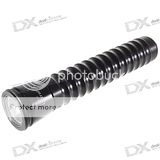
I joined this forum to learn about the Ultrafire W200 mods since I wanted to mod this light myself.
Since I noticed that some people (not only on this forum) were interested in the mod I was making, I decided to make a detailed report so here we go.
The mod I'm going to do is a conversion to an Ultrafire W200 using 2 LiIon batteries, a Seoul Semiconductor P7 LED and a driver with 3 modes (High/Medium/Low). This replaces a cree P4/Q5 LED with 'no' driver and 3 AA batteries. I don't have a lathe, so you should be able to make a similar mod even with no advanced tools.
Ingredients:
Ok, now that we now what we need, here's how I did it.
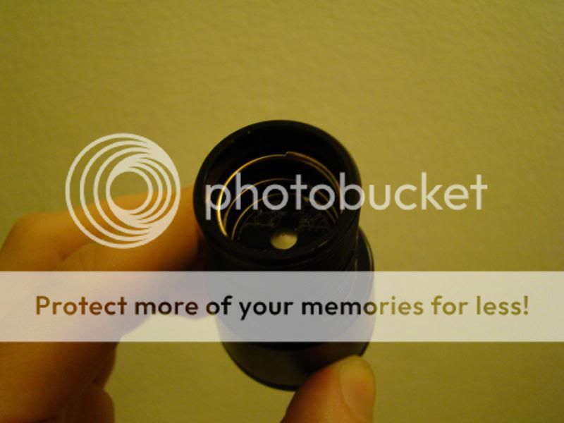
First thing to do is to disassemble the lamp. Please read this thread to find out how to do this. It is well illustrated so I'm not going to repeat that.
After measuring the height of the reflector, and the inside of the light head, I realised that there was an easy way to mount the led at the exact height that I needed. If I glued the LED on a metal circular plate with a thickness of 1mm, the height of the led with star, but without the dome lens, just fitted below the reflector. In fact, the star on which the LED is mounted had a thickness of 2mm, the base of the led (withouth the dome lens) is 2.5mm so including the the 1mm metal beneath the star, that makes 5.5mm. The reflector is 19mm high.
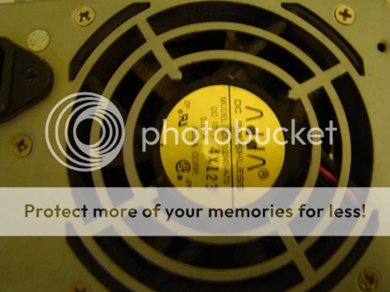
This is where I got the metal from:
 (I'm still looking for a better source for this
  )
)
I just cut the center of the fan grill from an old computer power supply. I clamped it between 2 washers of about the correct size, and sanded it down to the desired diameter. The washers helped keeping it round.
This was the result:
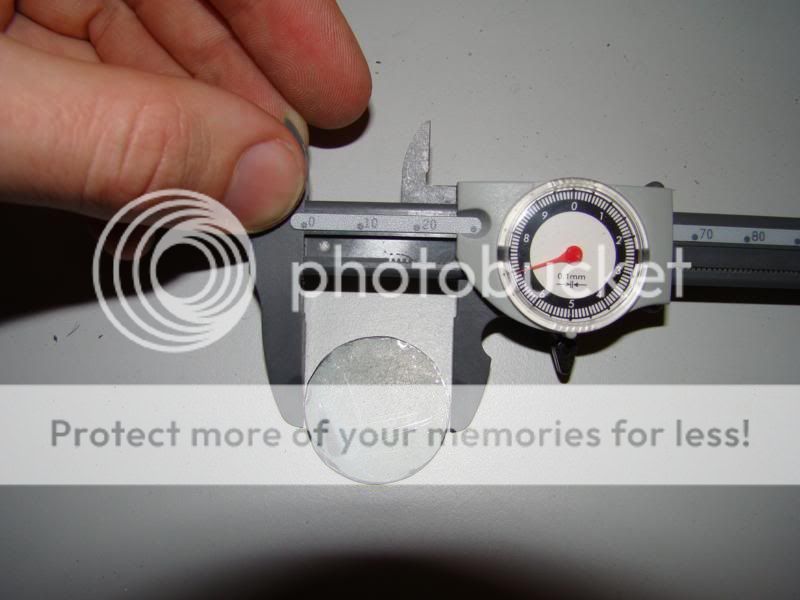
Diameter of 27mm fits perfectly in the light head.
Next challenge was how and where to mount the driver.
I figured it would need to be in the bottom part of the light head which restricted the diameter to 21mm maximum. On kaidomain, I found a driver for the P7 that was 19mm, perfect!
I read on this forum about this driver. Packhorse seemed to get good results with this driver. He mentionned that it needed to be fixed to a heatsink.
The metal that I'm going to put under the LED is propably not enought to transfer the heat to the light head since it only touches the light head on the outer circle of the metal.
So I need extra heatsinking on the back of the LED and for the driver... Since the driver needs to make contact with the batteries, I decided that putting a heatsink between the LED and the driver would be the easiest sollution.
I found an aluminum rod with a diameter of 20mm (21mm would have been better) and cut a little piece from it. After measuring the height of the batteries, the thickness of the driver and the available space above and below the batteries, I guestimated that 10mm would be a nice size to start with. Later, this proved to be a good guess.
I drilled a hole in it to fit a component (coil) of the driver. I also made a groove on the side and a little hole through the heatsink (under some strange angle) to allow the wires from the driver to get past the heatsink so I would be able to connect the wires to the LED. Since the diameter of the heatsink was only 20mm and the inner diameter of the light head was 21mm, I was affraid that I would have problems getting the heat away from the heatsink to the lighthead and eventually into the water. As you will see later, I used some pipe in the battery compartment. I also used a piece of this pipe (cut open at one site to be able to fit it around the heatsink) to fill the gap between the heatsink and the light head. Unfortunately, in mechanical design, 20mm+0.5mm+0.5mm is NOT equal to 21mm due to tollerances, so I had to use my dremel to sand it down a little to make it fit.
This was the end result:
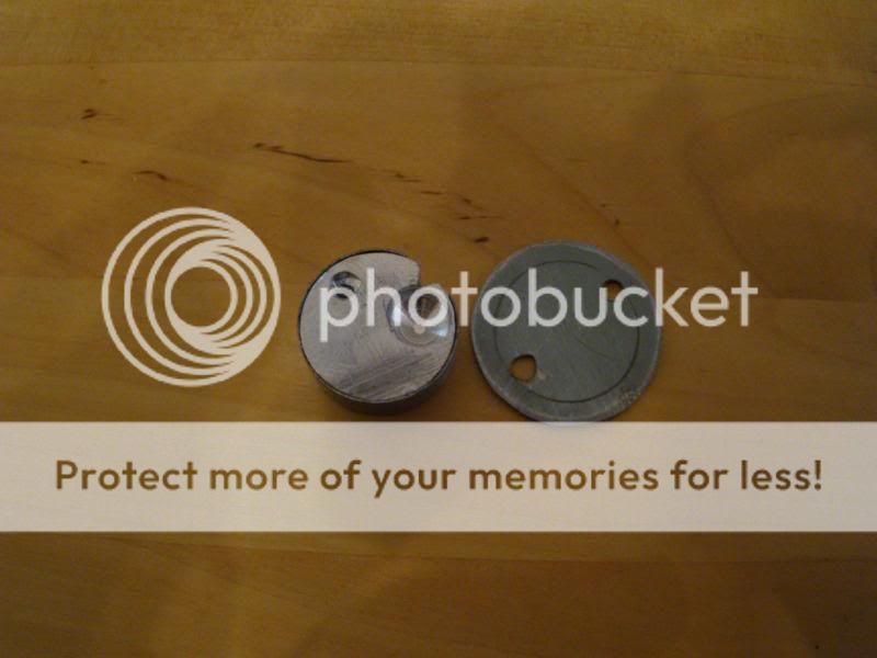
And this is how it is going to be assembled:
I once bought a P60 drop-in module from dealextreme that I initially planned to use in this mod, but I didn't use it since I decided to use the P7 LED. The drop-in module came with a spring with diamter 20.5mm or something so fitted the light head perfectly and was also big enough to fit around the LiIon batteries.
After figuring out where the - side of the batteries should be connected to the driver, I soldered the spring to the driver:
Next step was assembling my homemade LED pil. I used this thermal glue from dealextreme between the heatsink and the metal 'ring' around it and to glue the metal circle to the heatsink. That last part was a bit tricky since I had to make sure that the heatsink was exactly in the middle (or it would not fit in the light head) and that I was still able to put the wire of the driver through the heatsink. Putting it in the lighthead with the wire of the driver throught the hole while the glue was drying proved successful.
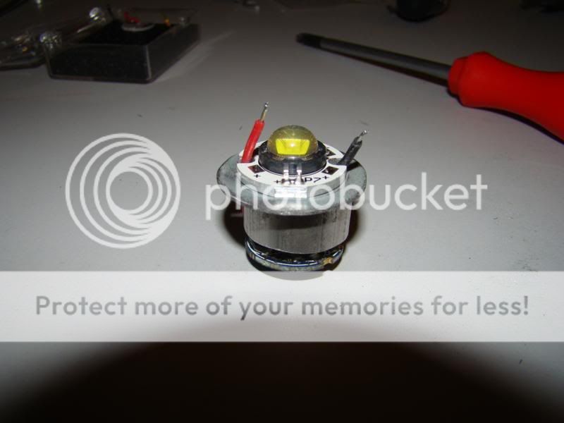
I then also glued the driver to the heatsink. When finished, it looked like this:
I also glued the LED in place on top of this, and soldered the wires to the leds, Red: + , black: -.
I didn't want to glue all this in the light head (in case I would want to use another LED in the future, or if something went wrong) so I used thermal grease that doesn't harden, also from dealextreme ;-), to put the LED with driver and heatsink in the light head:
Since the dome of the P7 LED is 9mm in diameter, and the original P4 LED is less, I also had to modify this. I tried to dril the hole bigger, although that was easier said than done. Nevertheless, I managed to get the hole a little larger than 9mm so the LED would not be stuck in the hole.
I could now reassemble the front lens. I had already replaced the O-ring that keeps the lens in place because the original O-ring was a bit damaged and also very soft (low quality). I also replaced the 3 o-rings that seal the connection with the battery compartment.
Next, I figured that the tube which holds the AA batteries was not going to work with the LiIon batteries, since they have a diameter of 18-19mm. The inner diameter of the delrin part of the lamp is just over 20mm so that leaves about 0.5mm space between the batteries and the delrin.
In the local hobby shop (Brico), I found a metal pipe with a wall thickness of 0.5mm and an outer diameter of 19mm and a length of 1m for 5€.
Initially I had cut a piece from the pipe that was the same length as the 2 batteries, but since I used the spring on the driver, this would be to long.
Also, the inner diameter of the pipe was a little too small for the batteries to slide in and out easily. This I solved by opening up the tube lengthwise at 1 side. Doing this allows you to stretch it open a little so the inner diameter becomes larger.
This also allowed the batteries to slide in and out of the tube without problems:
I reused the original spring that is located in the back of the light body. This spring connects the - of the batteries to the tube, which allows the electrons to reach the driver once the spring at the driver side touches the tube.
The + side of the top battery should touch the center pole of the driver.
After some trial and error, I settled with a tube length of about 126mm. This however depends on the height of the spring which I forgot to measure (from a standard drop-in module from dealextreme)...
This is the end result:
On the left, you can see the original ultrafire W200, on the right the modified W200.
I did a quick intensity comparison by taking a picture with fixed settings on my wall of both lights and looking at the intensity profile of a line through the center of the spot. I didn't take care that all batteries were charged, so this may not be a good comparison for total intensity, it's just to get an idea of the light pattern:
Now I'll just have to see how it performs while diving.
Here are some preliminarybeam shots for comparison, more to come if you want them.
Unmodified W200 with a Cree Q5 led:

Modified W200 with SSC P7 and stock reflector:

Final thoughts:
I hope you enjoyed the read. If something is unclear, just ask and I'll try to add the info.
Johan
I've been following this forum for a while and have been ordering some parts here and there, but never got around to finish the mod I had in mind.
I joined this forum to learn about the Ultrafire W200 mods since I wanted to mod this light myself.
Since I noticed that some people (not only on this forum) were interested in the mod I was making, I decided to make a detailed report so here we go.
The mod I'm going to do is a conversion to an Ultrafire W200 using 2 LiIon batteries, a Seoul Semiconductor P7 LED and a driver with 3 modes (High/Medium/Low). This replaces a cree P4/Q5 LED with 'no' driver and 3 AA batteries. I don't have a lathe, so you should be able to make a similar mod even with no advanced tools.
Ingredients:
- 1 Ultrafire W200 (dealextreme)
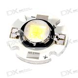
- 1 SSC P7 LED on a star (dealextreme)
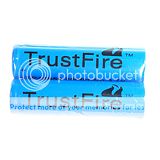
- 2 Lithium Ion batteries of type 18650 (dealextreme)
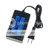
- LiIon 18650 charger
- (for most of Europe) Converter plug
- thermal glue (dealextreme)
- thermal paste (dealextreme)
- 3 mode driver for SSC P7 LED (Kaidomain)
- spring - there is one included in this DX item that might work
- metal pipe with diameter 19mm and 0.5mm wall thickness (local building material parts store - Brico)
- 1mm thick metal
- 20-21mm diameter aluminum rod for making a heatsink
Ok, now that we now what we need, here's how I did it.
First thing to do is to disassemble the lamp. Please read this thread to find out how to do this. It is well illustrated so I'm not going to repeat that.
After measuring the height of the reflector, and the inside of the light head, I realised that there was an easy way to mount the led at the exact height that I needed. If I glued the LED on a metal circular plate with a thickness of 1mm, the height of the led with star, but without the dome lens, just fitted below the reflector. In fact, the star on which the LED is mounted had a thickness of 2mm, the base of the led (withouth the dome lens) is 2.5mm so including the the 1mm metal beneath the star, that makes 5.5mm. The reflector is 19mm high.
This is where I got the metal from:
)I just cut the center of the fan grill from an old computer power supply. I clamped it between 2 washers of about the correct size, and sanded it down to the desired diameter. The washers helped keeping it round.
This was the result:
Diameter of 27mm fits perfectly in the light head.
Next challenge was how and where to mount the driver.
I figured it would need to be in the bottom part of the light head which restricted the diameter to 21mm maximum. On kaidomain, I found a driver for the P7 that was 19mm, perfect!
I read on this forum about this driver. Packhorse seemed to get good results with this driver. He mentionned that it needed to be fixed to a heatsink.
The metal that I'm going to put under the LED is propably not enought to transfer the heat to the light head since it only touches the light head on the outer circle of the metal.
So I need extra heatsinking on the back of the LED and for the driver... Since the driver needs to make contact with the batteries, I decided that putting a heatsink between the LED and the driver would be the easiest sollution.
I found an aluminum rod with a diameter of 20mm (21mm would have been better) and cut a little piece from it. After measuring the height of the batteries, the thickness of the driver and the available space above and below the batteries, I guestimated that 10mm would be a nice size to start with. Later, this proved to be a good guess.
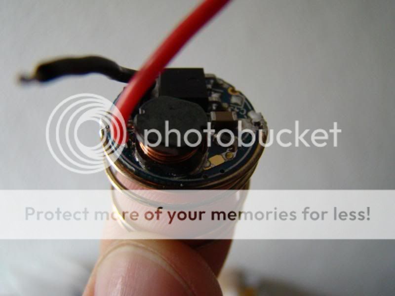
I drilled a hole in it to fit a component (coil) of the driver. I also made a groove on the side and a little hole through the heatsink (under some strange angle) to allow the wires from the driver to get past the heatsink so I would be able to connect the wires to the LED. Since the diameter of the heatsink was only 20mm and the inner diameter of the light head was 21mm, I was affraid that I would have problems getting the heat away from the heatsink to the lighthead and eventually into the water. As you will see later, I used some pipe in the battery compartment. I also used a piece of this pipe (cut open at one site to be able to fit it around the heatsink) to fill the gap between the heatsink and the light head. Unfortunately, in mechanical design, 20mm+0.5mm+0.5mm is NOT equal to 21mm due to tollerances, so I had to use my dremel to sand it down a little to make it fit.
This was the end result:
And this is how it is going to be assembled:
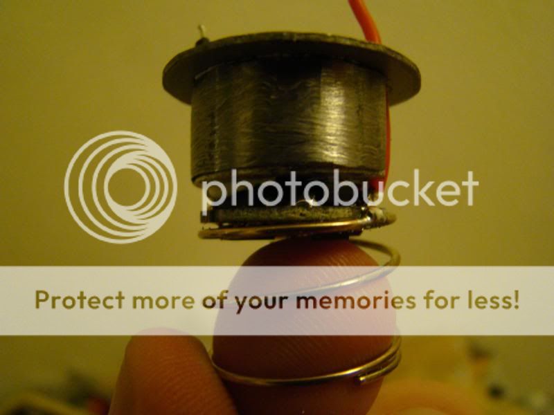
I once bought a P60 drop-in module from dealextreme that I initially planned to use in this mod, but I didn't use it since I decided to use the P7 LED. The drop-in module came with a spring with diamter 20.5mm or something so fitted the light head perfectly and was also big enough to fit around the LiIon batteries.
After figuring out where the - side of the batteries should be connected to the driver, I soldered the spring to the driver:
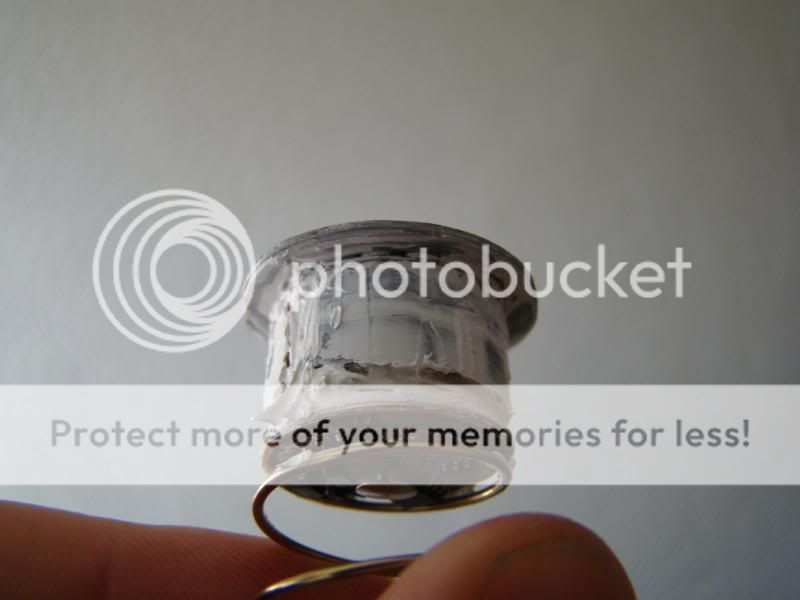
Next step was assembling my homemade LED pil. I used this thermal glue from dealextreme between the heatsink and the metal 'ring' around it and to glue the metal circle to the heatsink. That last part was a bit tricky since I had to make sure that the heatsink was exactly in the middle (or it would not fit in the light head) and that I was still able to put the wire of the driver through the heatsink. Putting it in the lighthead with the wire of the driver throught the hole while the glue was drying proved successful.
I then also glued the driver to the heatsink. When finished, it looked like this:
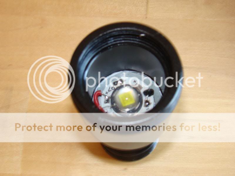
I also glued the LED in place on top of this, and soldered the wires to the leds, Red: + , black: -.
I didn't want to glue all this in the light head (in case I would want to use another LED in the future, or if something went wrong) so I used thermal grease that doesn't harden, also from dealextreme ;-), to put the LED with driver and heatsink in the light head:
Since the dome of the P7 LED is 9mm in diameter, and the original P4 LED is less, I also had to modify this. I tried to dril the hole bigger, although that was easier said than done. Nevertheless, I managed to get the hole a little larger than 9mm so the LED would not be stuck in the hole.
I could now reassemble the front lens. I had already replaced the O-ring that keeps the lens in place because the original O-ring was a bit damaged and also very soft (low quality). I also replaced the 3 o-rings that seal the connection with the battery compartment.
Next, I figured that the tube which holds the AA batteries was not going to work with the LiIon batteries, since they have a diameter of 18-19mm. The inner diameter of the delrin part of the lamp is just over 20mm so that leaves about 0.5mm space between the batteries and the delrin.
In the local hobby shop (Brico), I found a metal pipe with a wall thickness of 0.5mm and an outer diameter of 19mm and a length of 1m for 5€.
Initially I had cut a piece from the pipe that was the same length as the 2 batteries, but since I used the spring on the driver, this would be to long.
Also, the inner diameter of the pipe was a little too small for the batteries to slide in and out easily. This I solved by opening up the tube lengthwise at 1 side. Doing this allows you to stretch it open a little so the inner diameter becomes larger.
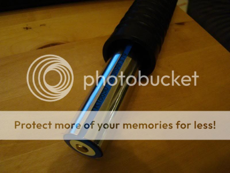
This also allowed the batteries to slide in and out of the tube without problems:
I reused the original spring that is located in the back of the light body. This spring connects the - of the batteries to the tube, which allows the electrons to reach the driver once the spring at the driver side touches the tube.
The + side of the top battery should touch the center pole of the driver.
After some trial and error, I settled with a tube length of about 126mm. This however depends on the height of the spring which I forgot to measure (from a standard drop-in module from dealextreme)...
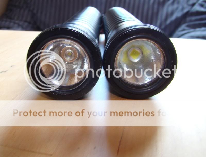
This is the end result:
On the left, you can see the original ultrafire W200, on the right the modified W200.
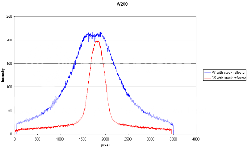
I did a quick intensity comparison by taking a picture with fixed settings on my wall of both lights and looking at the intensity profile of a line through the center of the spot. I didn't take care that all batteries were charged, so this may not be a good comparison for total intensity, it's just to get an idea of the light pattern:
Now I'll just have to see how it performs while diving.
Here are some preliminarybeam shots for comparison, more to come if you want them.
Unmodified W200 with a Cree Q5 led:
Modified W200 with SSC P7 and stock reflector:
Final thoughts:
- It took me some time to figure it all out, but once I had the components, it was actually quite easy to put it all together.
- The reflector is not designed for this LED, so the beam is more floody than the unmodified light. If I'd want a better focused P7 light, I'd need a bigger reflector, so that is not going to fit in this light. I haven't tried it with an aspheric though.
- It was fun to do
- I need to find a better source for the base plate under the LED and maybe also the heat sink.
- When used above the water, the light head warms up quite fast when on high, indicating that the heat transfer works well.
- I need to do more testing to get a good idea of the run-time with the 3 modes.
- need more beamshots - this will also allow me to calculate the beam angle.
- This build was a good introduction to using high power LEDs. It already got me thinking about my next build.
I hope you enjoyed the read. If something is unclear, just ask and I'll try to add the info.
Johan
