Android Mobile Phone control of pfodDevices - Completed - A Tutorial - Led Driver
Android™ Controlled LED Driver using pfodApp™
This tutorial extends the Bluetooth Controlled Led Driver to allow the LED to be controlled from your Android mobile.
NO Android programming is required!!
It replaces the original J2ME version with the Android version.
The pfodApp for Andriod provides a complete solution for controlling arbitrary microcontroller devices, such as Arduino, from your AndroidTM mobile phone.
For the Mobile Phone J2ME java version of the pfodApp see here.
These four posts are also available at
Part 1 – Introduction to pfodAppsTM/pfodDevices™
Part 2 -- Intoduction to pfodApp™ – the Mobile Phone Application
Part 3 – Led Controller pfodDevice™ Messages
Part 4 – Coding the Led Controller pfodDevice™
Introduction
This tutorial will first cover the communication protocol, pfod (Protocol For Operations Discovery), that is used to control the LED driver and show some of the Android screens that will be used to control the LED driver. The next section will introduce the Android pfodApp application and show how you can test out the screens from your PC. The last two sections will cover the design of the micro-pages that will be used to control the LED driver and the coding of the micro itself.
Part 1 – Introduction to pfodApps/pfodDevices
Why pfodDevices?
I found the bluetooth connectivity to the Mobile Phone Controlled Led Driver very useful and wanted to extend it to my other torches, led lighting and household devices. But I did not want to have to remember what each device could do and did not want to have to re-code the mobile phone application to support each new device. The solution I come up with was to define a simple Protocol For Operations Discovery (pfod) by which the mobile application asked the device what commands it supports and then lets the user choose one.
pfodDevices™ are devices that support this protocol, as defined in pfodSpecificationV1.2.pdf
pfodAppsTM are applications that connect to pfodDevices and display the commands available and let the user choose one.
pfodApps are like micro-browsers that display the micro-pages served by the pfodDevice. But the messages defined in the pfodSpecificationV1.2 are much simpler then HTML and are designed for easy implementation in micro devices such as Arduino. The maximum message size is 255 bytes.
Non-English languages are optionally supported by the pfodSpecificationV1.2.pdf , but are not implemented in the current Android pfodApp. If you are a non-English speaker and would like to help in testing the Android pfodApp to another language, contact me.
In this tutorial I will show the Android version of pfodApp and what is need to convert the Mobile Phone Controlled Led Driver into a pfodDevice. Even if you don't make the Led Controller, you can play around with the Andriod Bluetooth pfodApp using the bluetooth connection on your laptop or download the free pfodAppDemo, which shows examples of how all the pfodApp screens will look on your mobile.
pfodDevice and pfodApp are trade marks of Forward Computing and Control Pty. Ltd.
What can pfodDevices™ do?
Before going into the details, let's see how the Android Bluetooth pfodApp can control a simple pfodDevice™, in this case the pfod Led Controller.
To see larger selection of screens look at the pfod Specification or install the pfodAppDemo application on your Android.
On starting the Android Bluetooth pfodApp it shows the Connect To screen.
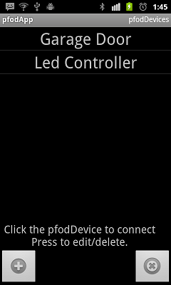
This lists the names of the Bluetooth pfodDevices you have setup. To add a new pfodDevice click Add button (+). See pfodAppForAndroidGettingStarted.pdf for how to set up these connections.
This Andriod Bluetooth pfodApp can control any device which has a bluetooth/serial connection and implements pfod (Protocol For Operations Discovery). The protocol itself does not mandate using bluetooth, other implementations could use wifi, internet or SMS to make the connection and transfer the messages.
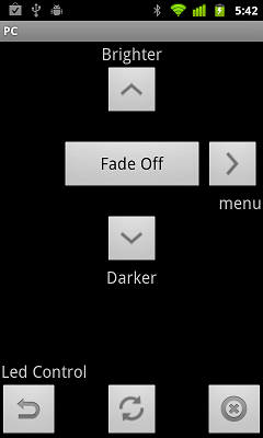
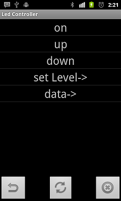
When you click on a pfodDevice to connect to,say the Led Controller, the pfodApp connects and requests the pfodDevice's main menu. In this the pfodDevice returns a Navigation Menu. Other devices might just show a selection list menu depending on their capabilities.
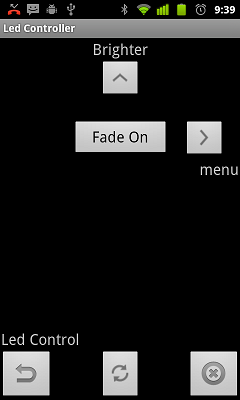
Pressing the "Fade On" button turns the Led on and updates the display with a "Darker" down button. Then, after a few seconds, when the Led has reached full brightness the display updates to
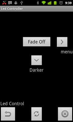
How does the pfodApp know that the Led has reached maximum brightness and that the "Brighter" button should no longer be shown.?
When the Led Controller sent the Navigation Menu, it also send a non-zero refresh interval. That tells the pfodApp to repeatedly re-request this menu each refresh interval. You can see these multiple requests and responses
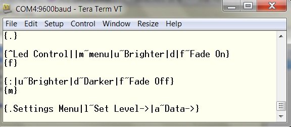
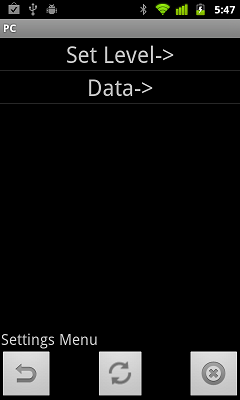
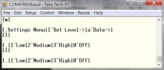
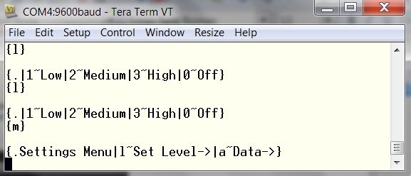
Pressing the right direction key sends the command associated with the Menu label to the pfod Led Controller. The pfod Led Controller sends back "Settings Menu e.g.
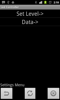
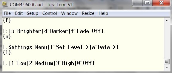
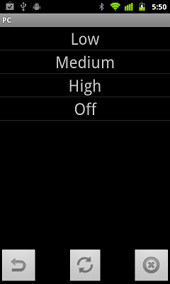
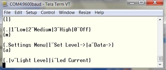
Sending the "Set Level" command, the pfod Led Controller responds with a new sub-menu which lets you set the Led level to High, Med, Low or Off
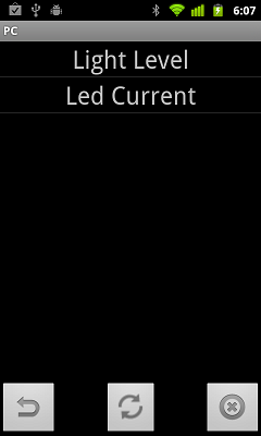
Sending the "Data" command, the pfod Led Controller responds with a sub-menu of
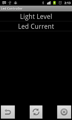
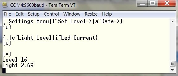
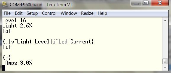
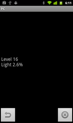
Sending the "Light Level" command, the pfod Led Controller responds with the Streaming Raw Data message and then sends the current light level details in free text.
Other possible messages a pfodDevice™ could respond with include requesting text input, numeric input and single and multi-selections from a list.
What makes this pfodApp mobile application so useful is that the one application can control many different devices. It is the device that tells the mobile what functionality is available. The mobile then just displays the commands and lets you choose. Languages other then English can also be supported.
Protocol For Operations Discovery (pfod)
The specification for pfod is detailed in the pfod Specification It defines the message formats and some minimal connection details. The specification does not define how the messages are displayed to the user.
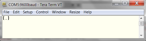
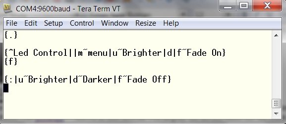
Here is another example of the initial connection message exchange. Each message, except streaming raw data, is contained within a start and end character { } . When the pfodApp mobile application establishes a connection, it first sends the getMainMenu message, {.} , to the pfodDevice. The pfodDevice responds with a menu of functionality that is supports. In this example the pfodDevice responds with{.|o~on|u~up|d~down|s~set Level->|a~data->} . This message defines a menu which defines 5 items on, up, down, set Level-> and data->
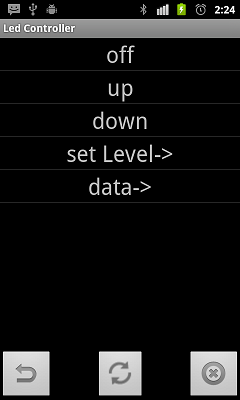
Each of these menu items is associated with a command that the pfodDevice will respond to. For example when the user selects the on menu item, the application will send the associated command o to the pfodDevice™ (as the message {o} ).
The pfodDevice™ then executes that command and responds to the application with some message, perhaps an empty one {}, to indicate the pfodDevice™ received the command and has executed it. In this case the pfod Led Controller responds with the message {:|o~off} This updates the display text for the o command to show off.
For a detailed description of the messages, examples and a sample displays, see the pfod Specification .
For simple devices, single letter commands are sufficient and no processing of user input is required. This minimizes the coding required in the micro-controller to implement the protocol. See the pfod Led Controller section for a detailed asm code example or see Arduino Garage Door remote control for an Arduino example.
The next section will cover setting connecting your Android mobile, via bluetooth, to a terminal session on your PC so that you can design and test the micro-pages your pfodDevice will serve to the pfodApp
Android is a trademark of Google Inc., Arduino is promoted by http://www.arduino.cc/
Android™ Controlled LED Driver using pfodApp™
This tutorial extends the Bluetooth Controlled Led Driver to allow the LED to be controlled from your Android mobile.
NO Android programming is required!!
It replaces the original J2ME version with the Android version.
The pfodApp for Andriod provides a complete solution for controlling arbitrary microcontroller devices, such as Arduino, from your AndroidTM mobile phone.
For the Mobile Phone J2ME java version of the pfodApp see here.
These four posts are also available at
Part 1 – Introduction to pfodAppsTM/pfodDevices™
Part 2 -- Intoduction to pfodApp™ – the Mobile Phone Application
Part 3 – Led Controller pfodDevice™ Messages
Part 4 – Coding the Led Controller pfodDevice™
Introduction
This tutorial will first cover the communication protocol, pfod (Protocol For Operations Discovery), that is used to control the LED driver and show some of the Android screens that will be used to control the LED driver. The next section will introduce the Android pfodApp application and show how you can test out the screens from your PC. The last two sections will cover the design of the micro-pages that will be used to control the LED driver and the coding of the micro itself.
Part 1 – Introduction to pfodApps/pfodDevices
Why pfodDevices?
I found the bluetooth connectivity to the Mobile Phone Controlled Led Driver very useful and wanted to extend it to my other torches, led lighting and household devices. But I did not want to have to remember what each device could do and did not want to have to re-code the mobile phone application to support each new device. The solution I come up with was to define a simple Protocol For Operations Discovery (pfod) by which the mobile application asked the device what commands it supports and then lets the user choose one.
pfodDevices™ are devices that support this protocol, as defined in pfodSpecificationV1.2.pdf
pfodAppsTM are applications that connect to pfodDevices and display the commands available and let the user choose one.
pfodApps are like micro-browsers that display the micro-pages served by the pfodDevice. But the messages defined in the pfodSpecificationV1.2 are much simpler then HTML and are designed for easy implementation in micro devices such as Arduino. The maximum message size is 255 bytes.
Non-English languages are optionally supported by the pfodSpecificationV1.2.pdf , but are not implemented in the current Android pfodApp. If you are a non-English speaker and would like to help in testing the Android pfodApp to another language, contact me.
In this tutorial I will show the Android version of pfodApp and what is need to convert the Mobile Phone Controlled Led Driver into a pfodDevice. Even if you don't make the Led Controller, you can play around with the Andriod Bluetooth pfodApp using the bluetooth connection on your laptop or download the free pfodAppDemo, which shows examples of how all the pfodApp screens will look on your mobile.
pfodDevice and pfodApp are trade marks of Forward Computing and Control Pty. Ltd.
What can pfodDevices™ do?
Before going into the details, let's see how the Android Bluetooth pfodApp can control a simple pfodDevice™, in this case the pfod Led Controller.
To see larger selection of screens look at the pfod Specification or install the pfodAppDemo application on your Android.
On starting the Android Bluetooth pfodApp it shows the Connect To screen.
This lists the names of the Bluetooth pfodDevices you have setup. To add a new pfodDevice click Add button (+). See pfodAppForAndroidGettingStarted.pdf for how to set up these connections.
This Andriod Bluetooth pfodApp can control any device which has a bluetooth/serial connection and implements pfod (Protocol For Operations Discovery). The protocol itself does not mandate using bluetooth, other implementations could use wifi, internet or SMS to make the connection and transfer the messages.
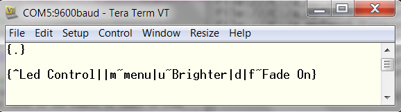
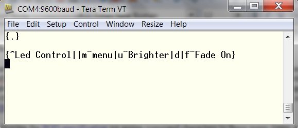
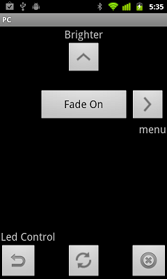
When you click on a pfodDevice to connect to,say the Led Controller, the pfodApp connects and requests the pfodDevice's main menu. In this the pfodDevice returns a Navigation Menu. Other devices might just show a selection list menu depending on their capabilities.
Pressing the "Fade On" button turns the Led on and updates the display with a "Darker" down button. Then, after a few seconds, when the Led has reached full brightness the display updates to
How does the pfodApp know that the Led has reached maximum brightness and that the "Brighter" button should no longer be shown.?
When the Led Controller sent the Navigation Menu, it also send a non-zero refresh interval. That tells the pfodApp to repeatedly re-request this menu each refresh interval. You can see these multiple requests and responses
Pressing the right direction key sends the command associated with the Menu label to the pfod Led Controller. The pfod Led Controller sends back "Settings Menu e.g.
Sending the "Set Level" command, the pfod Led Controller responds with a new sub-menu which lets you set the Led level to High, Med, Low or Off
Sending the "Data" command, the pfod Led Controller responds with a sub-menu of
Sending the "Light Level" command, the pfod Led Controller responds with the Streaming Raw Data message and then sends the current light level details in free text.
Other possible messages a pfodDevice™ could respond with include requesting text input, numeric input and single and multi-selections from a list.
What makes this pfodApp mobile application so useful is that the one application can control many different devices. It is the device that tells the mobile what functionality is available. The mobile then just displays the commands and lets you choose. Languages other then English can also be supported.
Protocol For Operations Discovery (pfod)
The specification for pfod is detailed in the pfod Specification It defines the message formats and some minimal connection details. The specification does not define how the messages are displayed to the user.
Here is another example of the initial connection message exchange. Each message, except streaming raw data, is contained within a start and end character { } . When the pfodApp mobile application establishes a connection, it first sends the getMainMenu message, {.} , to the pfodDevice. The pfodDevice responds with a menu of functionality that is supports. In this example the pfodDevice responds with{.|o~on|u~up|d~down|s~set Level->|a~data->} . This message defines a menu which defines 5 items on, up, down, set Level-> and data->
Each of these menu items is associated with a command that the pfodDevice will respond to. For example when the user selects the on menu item, the application will send the associated command o to the pfodDevice™ (as the message {o} ).
The pfodDevice™ then executes that command and responds to the application with some message, perhaps an empty one {}, to indicate the pfodDevice™ received the command and has executed it. In this case the pfod Led Controller responds with the message {:|o~off} This updates the display text for the o command to show off.
For a detailed description of the messages, examples and a sample displays, see the pfod Specification .
For simple devices, single letter commands are sufficient and no processing of user input is required. This minimizes the coding required in the micro-controller to implement the protocol. See the pfod Led Controller section for a detailed asm code example or see Arduino Garage Door remote control for an Arduino example.
The next section will cover setting connecting your Android mobile, via bluetooth, to a terminal session on your PC so that you can design and test the micro-pages your pfodDevice will serve to the pfodApp
Android is a trademark of Google Inc., Arduino is promoted by http://www.arduino.cc/
Last edited: