
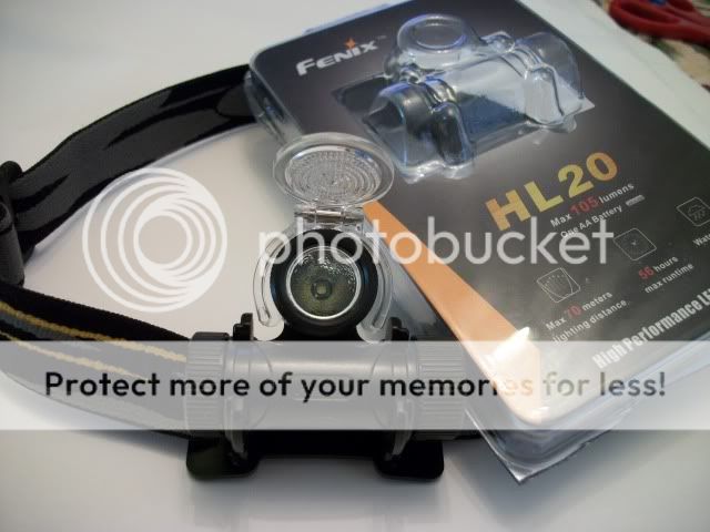
I had this HL20 sitting unused, and decided that it would be a good candidate for an XP-G mod.
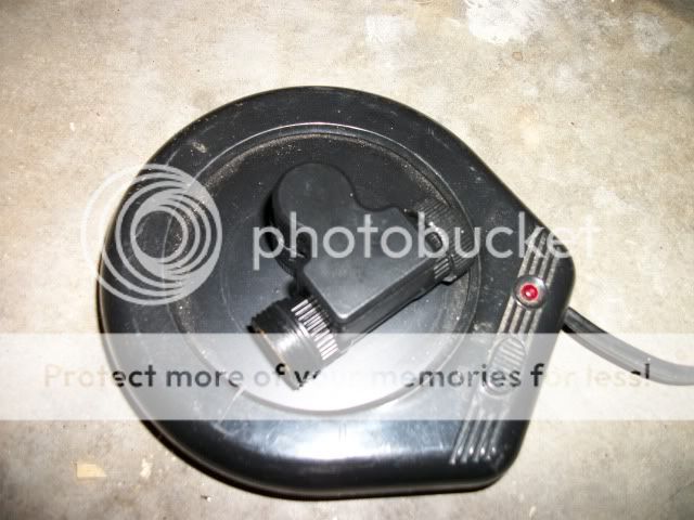
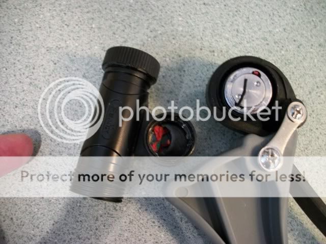
The obvious first task was opening the head. I like to use a mug warmer to soften the epoxy on most lights, and figured that it should work on the HL20 as well.
The next step is to use my trusty strap wrench to get the head open. It worked after repositioning the strap. I was able to unscrew the head off with my hands once the epoxy seal was broken.
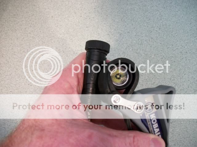
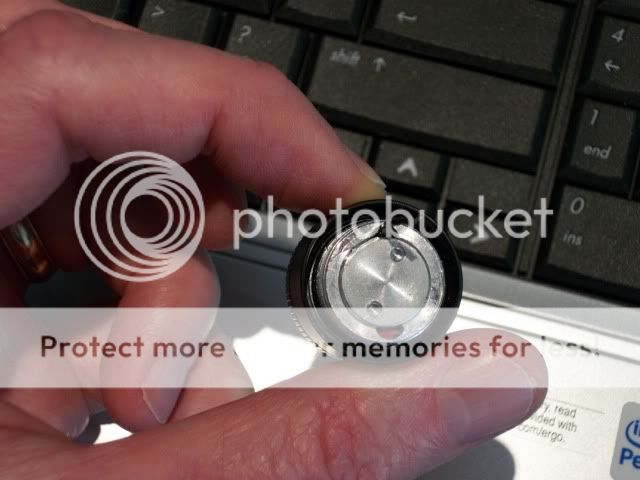
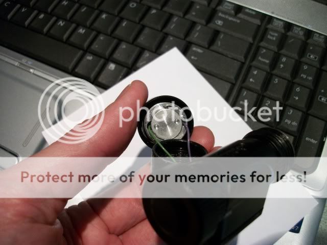
Uh oh... broken wires. The LED is part of the head that I just unscrewed. Is this mod doomed? I am an eternal optimist, so I'm not too worried at this point.
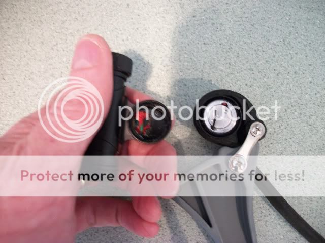
A closeup shot showing the broken wires, and the screw in heatsink.
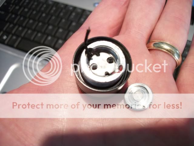
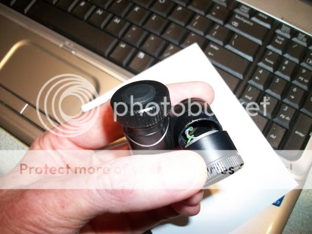
The screw-in heatsink removed from the head, and the back of the LED board.
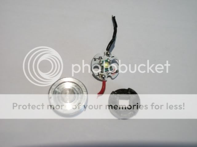
All of the parts in the head laid out. The black centering ring fits over the LED, and is centered by the back of the reflector. This should ensure a perfectly centered LED every time. Good design, Fenix.
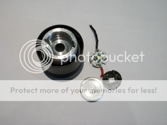
An even closer view of the heatsink, LED board and centering ring.
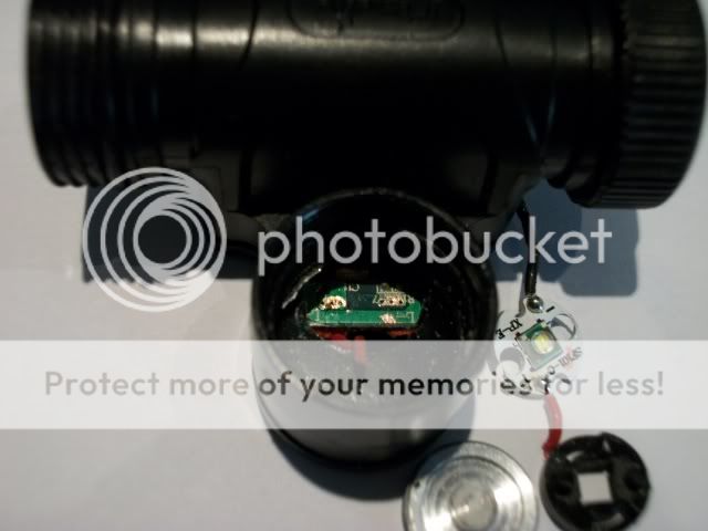
A look into the body of the headlamp showing the PCB. I removed some of the solder mask to test whether the positive wire and the pad on the board are connected. They are connected! I made the assumption that the pad on the other side was for the negative LED lead.
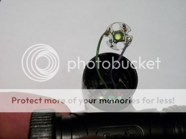
After soldering the XP-G onto the existing board, I soldered teflon wires onto the pads that I exposed earlier. A quick connection to the LED board, and it is time for a quick test to verify that the mod is going to work. Success!
The centering ring is in place, ready for installation into the head.
The LED installed in the head, and the heatsink screwed back into place.
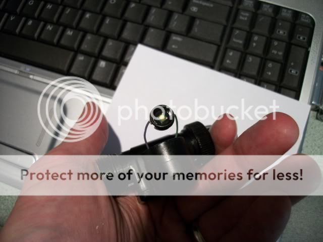
Look into the gap between the head and body. See the twisted wires to the
LED? I figure that If I wind the wires counter-clockwise, that when I screw the head on, it will not bind the wires too bad.
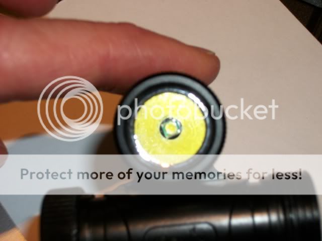
OK, the head is threaded back on, now it is time to test the light. It works. And the LED is perfectly focused, as it should be.
The obvious first task was opening the head. I like to use a mug warmer to soften the epoxy on most lights, and figured that it should work on the HL20 as well.
The next step is to use my trusty strap wrench to get the head open. It worked after repositioning the strap. I was able to unscrew the head off with my hands once the epoxy seal was broken.
Uh oh... broken wires. The LED is part of the head that I just unscrewed. Is this mod doomed? I am an eternal optimist, so I'm not too worried at this point.
A closeup shot showing the broken wires, and the screw in heatsink.
The screw-in heatsink removed from the head, and the back of the LED board.
All of the parts in the head laid out. The black centering ring fits over the LED, and is centered by the back of the reflector. This should ensure a perfectly centered LED every time. Good design, Fenix.
An even closer view of the heatsink, LED board and centering ring.
A look into the body of the headlamp showing the PCB. I removed some of the solder mask to test whether the positive wire and the pad on the board are connected. They are connected! I made the assumption that the pad on the other side was for the negative LED lead.
After soldering the XP-G onto the existing board, I soldered teflon wires onto the pads that I exposed earlier. A quick connection to the LED board, and it is time for a quick test to verify that the mod is going to work. Success!
The centering ring is in place, ready for installation into the head.
The LED installed in the head, and the heatsink screwed back into place.
Look into the gap between the head and body. See the twisted wires to the
LED? I figure that If I wind the wires counter-clockwise, that when I screw the head on, it will not bind the wires too bad.
OK, the head is threaded back on, now it is time to test the light. It works. And the LED is perfectly focused, as it should be.