
My how far we have come in just a few years. From top-O-the-line LEDs that put out 30 lumens to now into the thousands of lumens. From when the most powerful modern LED had a maximum drive rating of 350mA as compared to todays 13A+. Most importantly to the point of this thread is the current density has risen to almost 4Xs the original Luxeons.
Despite this massive increase in current density the industry still uses the same old mcpcb technology with little in the way of improvements. While more than sufficient for some tasks for others they fall woefully short. Running these new large die-high current LEDs-in flashlights that were never designed for them in the first place certainly falls in the latter category. Some of us crazy folk also like to overdrive our LEDs to eek out every last drop of light.
I am always amazed at how far people go to maximize the lumens making sure they have the latest bin and special drivers, AR coated glass, the best thermal compound they can find, resistance mods, and list goes on. All this effort and so many people miss the worst offender in their light. The mcpcb. This is the greatest bottleneck for heat getting out of most of these high power flashlights. You could have a giant chunk of dry ice as the last portion of your heatsink but if you have a saltine stuck in between your LED and the ice you wont be moving the heat too terribly fast. Remember that the closer you get to the LED die the more critical it is that there is a good thermal conductor.
What am going to be doing in this thread is using it as a repository for some of my thermal tests and showing some ways to improve the heat extraction. Hopefully you find it enlightening. The goal is to help more people put greater effort into the thermal side of things. I know it's not easy as there aren't really any proper off-the-shelf solutions so this will require some DIY work. It's worth it!
TheTests________________________
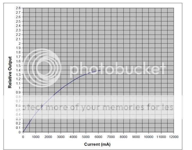
The first one I want to show you is a test jtr1962 did of an XP-G R5 overlayed on my test of the same bin and type LED. The difference is how we managed the thermal side of things. Both of us have it mounted to a large heatsink to shed all that heat but as jtr1962 said about his setup it was a fairly lousy thermal path. Keep in mind that what I am doing here is in no way intended to take the shine off of his immense work in getting hard facts on whether these LEDs live up to there billing. His tests just provided me data to help me make a point for this thread.
So here we have my test of an XP-G R5 with thinned ceramic backer epoxied to solid copper in blue, my test of an XP-G R5 with a thinned ceramic backer epoxied to a heat-pipe in yellow, and jtr1962's in red.

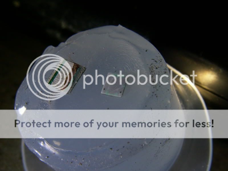
So why the big disparity in the amount of current my XP-G could handle vs his? A superior thermal path. Some of you may remember me shaving down the backs of LEDs in the past. These new LEDs are so tiny that I had to come up with a new way to handle them. I put a mold release agent over the LED and then poured mold silicone over it(note this is not the stuff you get at the store. It has a catalyst that is added). After setting up I peeled it up off the glass with the LED being held as secure as you please allowing me to use a diamond coated disk in my dremel to shave the ceramic down. When done I gently pried the LED out of the silicone. This might also work with the HomeDepot variety of silicone as well but I can't be sure. You would want to keep the blob relatively small to avoid having a gummy center that will not dry. You might also be able to use something like a very thin layer of Vaseline as a release agent. That is not an official recommendation as I have not tried it to know for sure.
The shaved XP-G is on the right.
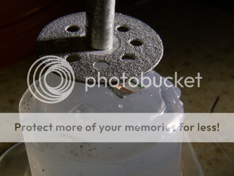
Here is the diamond coated disk I used. Should be able to find it at Lowes or Home Depot with all the other Dremel attachments. You want to tilt it ever so slightly and constantly change your direction of attack so that you wear the surface down evenly.

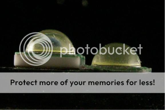
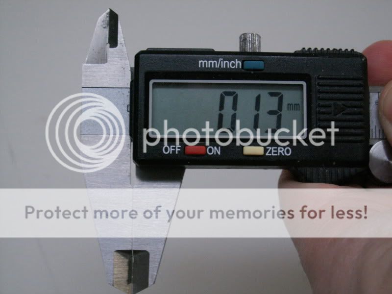
The ceramic is now about .1mm thick.
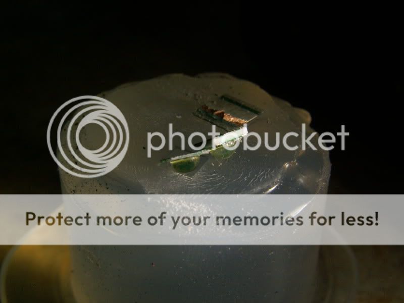
After shaving the back I used Arctic Silver to bond it to a piece of copper 1/8th thick. It would be advisable to scrape the silicone off the top pads and tin before attaching to the copper base. Otherwise you will find it next to impossible to tin those tiny pads. You'll notice I added kapton tape to hold the wires in place. Without this the tiny solder points joining the wires to the LED would snap at the tinyest movement. You must have the wires fixed somehow before you solder.
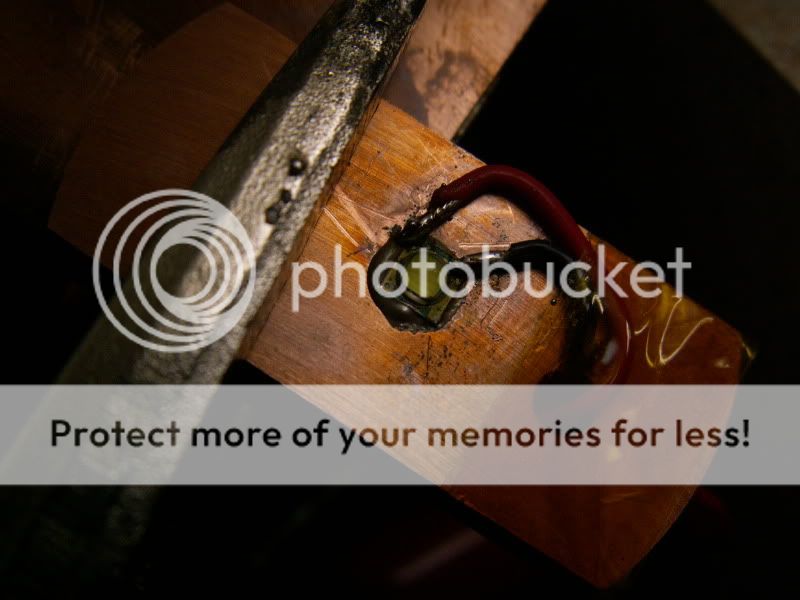
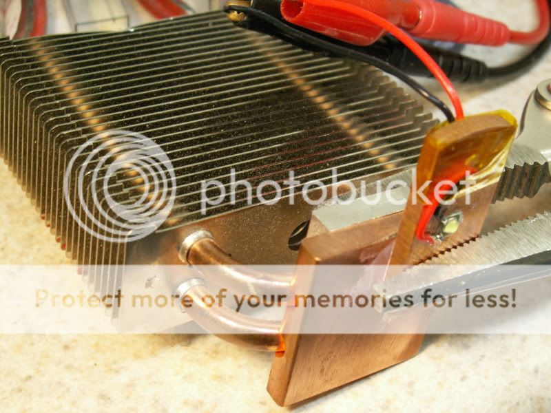
Here is the simple little setup to get rid of the heat. Not pretty but it works.
_______________________________
This next one is my test of an XL-M T6 soldered to a solid piece of copper. Some people have reported that there is not much in the way of lumens to be had past 3A. That may be true if you have a bad thermal path but as you can see there is quite a bit more past the maximum rating of 3A.
MCPCB tests_________________________
This section will contain information on the best and worst MCPCB performers. I will reserve my initial opinions until I can do proper testing on all my boards. I am waiting on a few to come in from across the ocean so the full test will not be posted until then. If you have some you want me to test PM me.
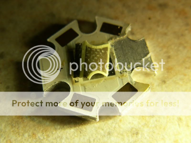
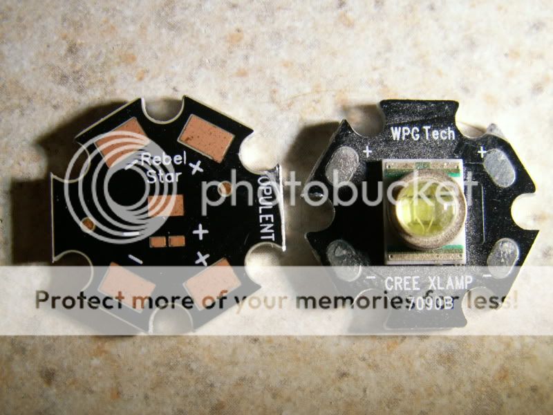
First off let's see why I don't care for MCPCBs. MCPCB stands for Metal Core Printed Circuit Board. Nothing wrong with the metal core part. It is the material used to create electrical insulation between the metal core and the top side traces that is the culprit. Here is a picture of a board for the XR-E bought from Cutter. The chip I pealed off is laid upside down. If you look close you will notice the glass fibers that make up the insulatory layer. The glass is part of a composite along with epoxy.
Here is how thick I measured the laminated layer without the metal traces taken into account.
Here's a couple more that will be tested.
__________________
More to come. Among other things I will also be testing LEDs on heat pipes.
Despite this massive increase in current density the industry still uses the same old mcpcb technology with little in the way of improvements. While more than sufficient for some tasks for others they fall woefully short. Running these new large die-high current LEDs-in flashlights that were never designed for them in the first place certainly falls in the latter category. Some of us crazy folk also like to overdrive our LEDs to eek out every last drop of light.
I am always amazed at how far people go to maximize the lumens making sure they have the latest bin and special drivers, AR coated glass, the best thermal compound they can find, resistance mods, and list goes on. All this effort and so many people miss the worst offender in their light. The mcpcb. This is the greatest bottleneck for heat getting out of most of these high power flashlights. You could have a giant chunk of dry ice as the last portion of your heatsink but if you have a saltine stuck in between your LED and the ice you wont be moving the heat too terribly fast. Remember that the closer you get to the LED die the more critical it is that there is a good thermal conductor.
What am going to be doing in this thread is using it as a repository for some of my thermal tests and showing some ways to improve the heat extraction. Hopefully you find it enlightening. The goal is to help more people put greater effort into the thermal side of things. I know it's not easy as there aren't really any proper off-the-shelf solutions so this will require some DIY work. It's worth it!
TheTests________________________
The first one I want to show you is a test jtr1962 did of an XP-G R5 overlayed on my test of the same bin and type LED. The difference is how we managed the thermal side of things. Both of us have it mounted to a large heatsink to shed all that heat but as jtr1962 said about his setup it was a fairly lousy thermal path. Keep in mind that what I am doing here is in no way intended to take the shine off of his immense work in getting hard facts on whether these LEDs live up to there billing. His tests just provided me data to help me make a point for this thread.
So here we have my test of an XP-G R5 with thinned ceramic backer epoxied to solid copper in blue, my test of an XP-G R5 with a thinned ceramic backer epoxied to a heat-pipe in yellow, and jtr1962's in red.
So why the big disparity in the amount of current my XP-G could handle vs his? A superior thermal path. Some of you may remember me shaving down the backs of LEDs in the past. These new LEDs are so tiny that I had to come up with a new way to handle them. I put a mold release agent over the LED and then poured mold silicone over it(note this is not the stuff you get at the store. It has a catalyst that is added). After setting up I peeled it up off the glass with the LED being held as secure as you please allowing me to use a diamond coated disk in my dremel to shave the ceramic down. When done I gently pried the LED out of the silicone. This might also work with the HomeDepot variety of silicone as well but I can't be sure. You would want to keep the blob relatively small to avoid having a gummy center that will not dry. You might also be able to use something like a very thin layer of Vaseline as a release agent. That is not an official recommendation as I have not tried it to know for sure.
The shaved XP-G is on the right.
Here is the diamond coated disk I used. Should be able to find it at Lowes or Home Depot with all the other Dremel attachments. You want to tilt it ever so slightly and constantly change your direction of attack so that you wear the surface down evenly.
The ceramic is now about .1mm thick.
After shaving the back I used Arctic Silver to bond it to a piece of copper 1/8th thick. It would be advisable to scrape the silicone off the top pads and tin before attaching to the copper base. Otherwise you will find it next to impossible to tin those tiny pads. You'll notice I added kapton tape to hold the wires in place. Without this the tiny solder points joining the wires to the LED would snap at the tinyest movement. You must have the wires fixed somehow before you solder.
Here is the simple little setup to get rid of the heat. Not pretty but it works.
_______________________________
This next one is my test of an XL-M T6 soldered to a solid piece of copper. Some people have reported that there is not much in the way of lumens to be had past 3A. That may be true if you have a bad thermal path but as you can see there is quite a bit more past the maximum rating of 3A.
MCPCB tests_________________________
This section will contain information on the best and worst MCPCB performers. I will reserve my initial opinions until I can do proper testing on all my boards. I am waiting on a few to come in from across the ocean so the full test will not be posted until then. If you have some you want me to test PM me.
First off let's see why I don't care for MCPCBs. MCPCB stands for Metal Core Printed Circuit Board. Nothing wrong with the metal core part. It is the material used to create electrical insulation between the metal core and the top side traces that is the culprit. Here is a picture of a board for the XR-E bought from Cutter. The chip I pealed off is laid upside down. If you look close you will notice the glass fibers that make up the insulatory layer. The glass is part of a composite along with epoxy.
Here is how thick I measured the laminated layer without the metal traces taken into account.
Here's a couple more that will be tested.
__________________
More to come. Among other things I will also be testing LEDs on heat pipes.
Last edited: