
samgab
Flashlight Enthusiast
I have a 4-pack of new eneloops that I recently bought.
I just ran 1A charge and 1A discharge cycles on them all, using my Turnigy Accucell 8150 Hobby charger. I then corrected the data to account for the measured readout error the Hobby charger has in current and to correct for voltage drop through the wire I use. And here are the results in chart form:
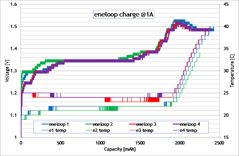
Charge:
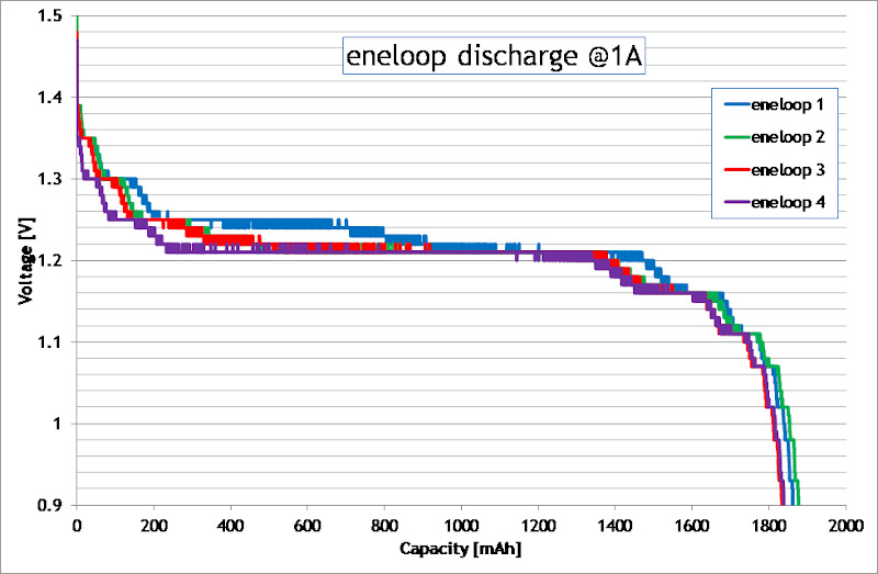
Discharge:
Musings on the results:
When charging, I have the -ΔV cutoff set to 5mV.
I also have the Temp max set to 40°C.
Only eneloop #2 (green) terminated based on -ΔV in this test. In all the other cases, termination was by max temp, although you can clearly see that the cells were fully charged by the curve. There just wasn't enough of a -ΔV to trigger the 5mV termination. This shows why it is so important to have a max temp, or even better, a ΔT/Δt (delta of temperature over delta of time) cutoff. As well as ideally a max mAh and a max time cutoff too.
I also had set a max mAh of 2500mAh, and a max time of 150 minutes, but neither of these termination methods was reached in the the tests, because in the case of eneloop #2 -ΔV activated, and in the cases of eneloops #1, 3, and 4; the max temp cutoff activated.
I think I would be better to tweak the max mAh to something like 2200mAh, looking at the chart. Once the curve flattens out after the -ΔV, any further charging is fairly pointless and possibly just damaging to the cell.
I might try the same tests again but using a 2A rate. Maybe there will be a bigger -ΔV signal at that rate and they might all terminate using that method at that rate, or maybe even at 1.5A.
I just ran 1A charge and 1A discharge cycles on them all, using my Turnigy Accucell 8150 Hobby charger. I then corrected the data to account for the measured readout error the Hobby charger has in current and to correct for voltage drop through the wire I use. And here are the results in chart form:
Charge:
Discharge:
Musings on the results:
When charging, I have the -ΔV cutoff set to 5mV.
I also have the Temp max set to 40°C.
Only eneloop #2 (green) terminated based on -ΔV in this test. In all the other cases, termination was by max temp, although you can clearly see that the cells were fully charged by the curve. There just wasn't enough of a -ΔV to trigger the 5mV termination. This shows why it is so important to have a max temp, or even better, a ΔT/Δt (delta of temperature over delta of time) cutoff. As well as ideally a max mAh and a max time cutoff too.
I also had set a max mAh of 2500mAh, and a max time of 150 minutes, but neither of these termination methods was reached in the the tests, because in the case of eneloop #2 -ΔV activated, and in the cases of eneloops #1, 3, and 4; the max temp cutoff activated.
I think I would be better to tweak the max mAh to something like 2200mAh, looking at the chart. Once the curve flattens out after the -ΔV, any further charging is fairly pointless and possibly just damaging to the cell.
I might try the same tests again but using a 2A rate. Maybe there will be a bigger -ΔV signal at that rate and they might all terminate using that method at that rate, or maybe even at 1.5A.
")