Mike S
Newly Enlightened
- Joined
- Apr 29, 2011
- Messages
- 132
I've been playing with this circuit on and off for a while now. It uses the Linear LTC3490 driver IC. Input voltage can be between ~0.8-3.2V and it outputs a constant 350 mA on fresh cells. I've had a couple of problems getting it to function correctly.
The first light it was going to be used in was an inexpensive single cell light. It originally had a type of joule thief circuit that powered a 5 mm LED. It would draw a little over 600 mA at the tail cap and the LED must have had 5 or 6 dies in it because current at the emitter was close to 250 mA.
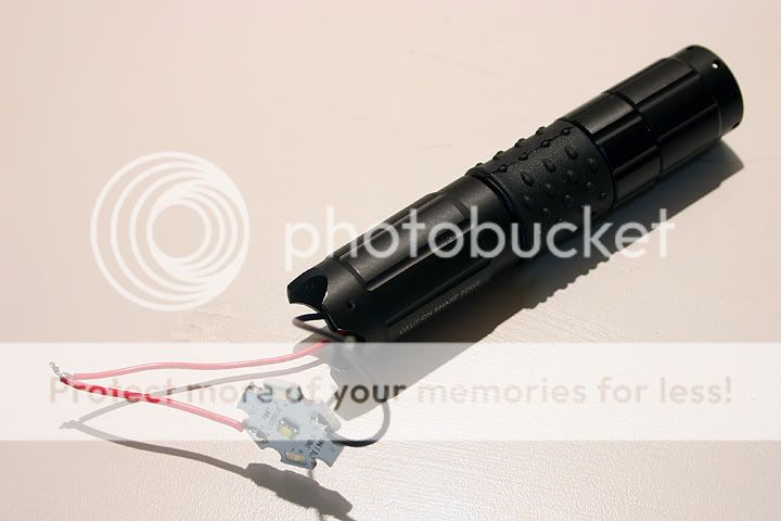
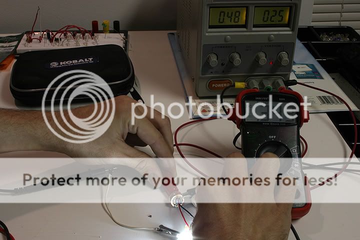
When I put the LTC3490 circuit together, I soldered a couple of wires to the positive and negative pads so that it could be tested outside of the flashlight. A NiMH or lithium primary would be pinched between the wires and the XP-G lit up perfectly. Current at the LED was a fairly constant 340 mA. Current at the cell would start at roughly 800 mA and then climb to about 1600 mA, which is what the datasheet shows as typical. The problem was that the driver IC was getting hot after a couple of seconds. This didn't happen every time. It seemed to occur mostly when the connection to the cell was poor. Sometimes the wires would slip as they were being pressed to the cell. If a good connection was made on the first try, there was no heat, or so it seemed that way. I figured once the driver was in the light, the switch would take care of the poor connection. It didn't. Actually the IC heats up every time the switch is on, but there's also a new problem. There is way too much resistance in the tail cap.
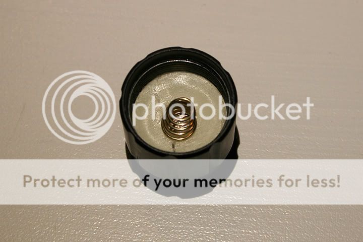
With a single cell light, the datasheet says 1 ohm of resistance has a significant effect on the output. At the LED, I'm seeing 220 mA instead of 340 with the switch in place. With the switch bypassed, the output goes back up to 340 mA. Is there anything that be done to this cheap switch other than bypassing the spring with a piece of wire? It looks like it's pressed and might have to be drilled or cut out.
Anyways those are the two main problems. Heat and tail cap resistance. Actually, later on I killed this driver when I was screwing down the tail cap. The switch must have been on because the LED flickered a few times. Once it was tightened down, the LED would no longer light up. I've never worked with an IC that was so sensitive to poor connections, but then again, I've never built a boost circuit like this before. Just the occasional joule thief.
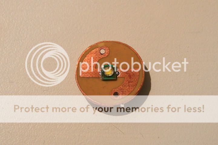
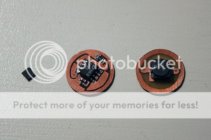
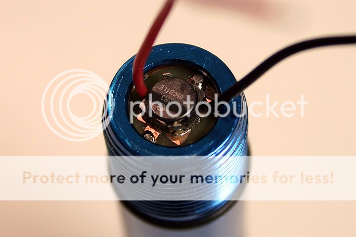
Here are some photos of the first hand soldered PCB. The output cap is too far away from the IC, the traces were too thin and the pull down resistor is way too large. I wonder if the length and width of the traces had anything to do with the heat?
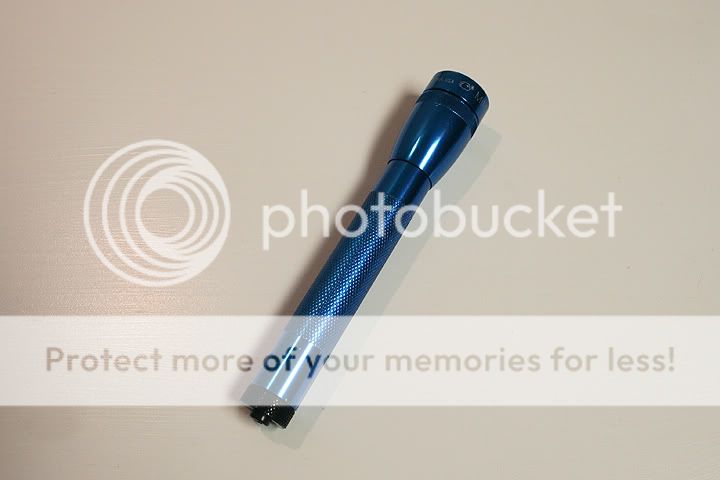
This is the light. It's my brother's flashlight and was originally modded with an AMC7135/14500 set up. He's too careless to use a lithium ion cell and constantly allows the protection circuit to trip. That why we're looking to AA boost circuits so that he can use a more stable power source.
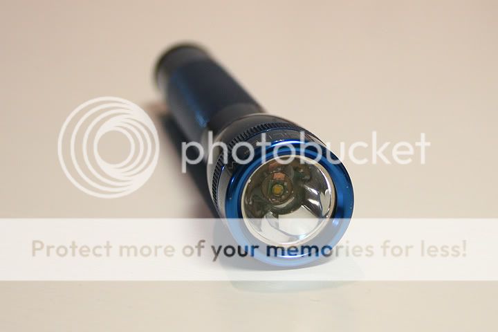
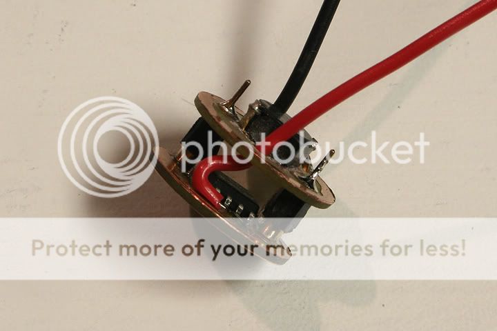
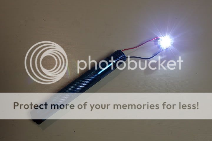
This is the latest build. It's a 15 year old incan minimag. It was modded earlier with a Nite Ize drop-in that made it a whiter light, but not a brighter light. The tail switch was reused for this 1W boost circuit.
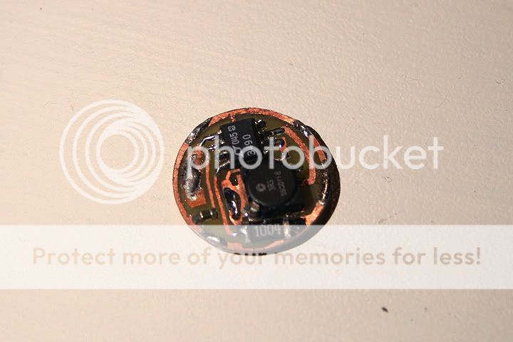
The 14 mm inner diameter made it difficult to fit all the components onto one board. Since that plastic spacer needs to be removed and takes up 8 or 9 mm, it made sense to use a double layer PCB and move the inductor to the top. It fills the gap perfectly. The IC on the far left is the LTC3490 in a "DD" package. Way too small to work with. After several failed reflow soldering attempts I switch to the SOIC-8.
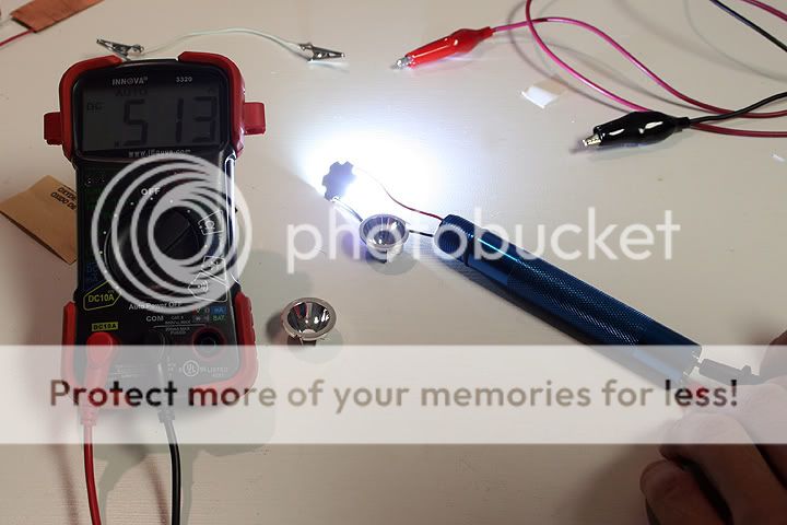
Current at tail cap with 2 NiMH Enercell's charged to 1.32V.
I still have to make a small heat sink for the XP-G or XP-E and figure out which reflector to use.
The first light it was going to be used in was an inexpensive single cell light. It originally had a type of joule thief circuit that powered a 5 mm LED. It would draw a little over 600 mA at the tail cap and the LED must have had 5 or 6 dies in it because current at the emitter was close to 250 mA.
When I put the LTC3490 circuit together, I soldered a couple of wires to the positive and negative pads so that it could be tested outside of the flashlight. A NiMH or lithium primary would be pinched between the wires and the XP-G lit up perfectly. Current at the LED was a fairly constant 340 mA. Current at the cell would start at roughly 800 mA and then climb to about 1600 mA, which is what the datasheet shows as typical. The problem was that the driver IC was getting hot after a couple of seconds. This didn't happen every time. It seemed to occur mostly when the connection to the cell was poor. Sometimes the wires would slip as they were being pressed to the cell. If a good connection was made on the first try, there was no heat, or so it seemed that way. I figured once the driver was in the light, the switch would take care of the poor connection. It didn't. Actually the IC heats up every time the switch is on, but there's also a new problem. There is way too much resistance in the tail cap.
With a single cell light, the datasheet says 1 ohm of resistance has a significant effect on the output. At the LED, I'm seeing 220 mA instead of 340 with the switch in place. With the switch bypassed, the output goes back up to 340 mA. Is there anything that be done to this cheap switch other than bypassing the spring with a piece of wire? It looks like it's pressed and might have to be drilled or cut out.
Anyways those are the two main problems. Heat and tail cap resistance. Actually, later on I killed this driver when I was screwing down the tail cap. The switch must have been on because the LED flickered a few times. Once it was tightened down, the LED would no longer light up. I've never worked with an IC that was so sensitive to poor connections, but then again, I've never built a boost circuit like this before. Just the occasional joule thief.
Here are some photos of the first hand soldered PCB. The output cap is too far away from the IC, the traces were too thin and the pull down resistor is way too large. I wonder if the length and width of the traces had anything to do with the heat?
This is the light. It's my brother's flashlight and was originally modded with an AMC7135/14500 set up. He's too careless to use a lithium ion cell and constantly allows the protection circuit to trip. That why we're looking to AA boost circuits so that he can use a more stable power source.
This is the latest build. It's a 15 year old incan minimag. It was modded earlier with a Nite Ize drop-in that made it a whiter light, but not a brighter light. The tail switch was reused for this 1W boost circuit.
The 14 mm inner diameter made it difficult to fit all the components onto one board. Since that plastic spacer needs to be removed and takes up 8 or 9 mm, it made sense to use a double layer PCB and move the inductor to the top. It fills the gap perfectly. The IC on the far left is the LTC3490 in a "DD" package. Way too small to work with. After several failed reflow soldering attempts I switch to the SOIC-8.
Current at tail cap with 2 NiMH Enercell's charged to 1.32V.
I still have to make a small heat sink for the XP-G or XP-E and figure out which reflector to use.
")