How to find fault in my simple rectifier circuit?

seanspotatobusiness

Newly Enlightened
Joined
Jul 12, 2010
Messages
81
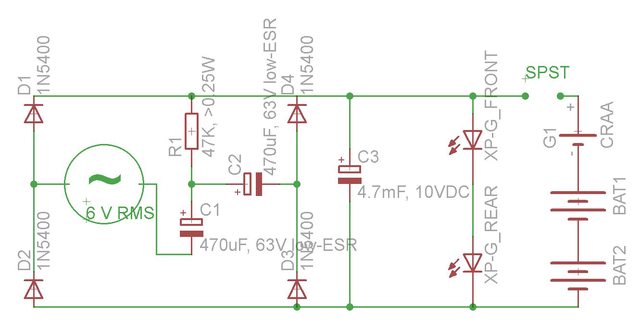
I made this circuit, based on a website with designs to power LEDs using a dynamo. In the breadboard, it worked as planned. However, when I soldered the components into stripboard, it didn't work. I tried using my multimeter to check the diodes and when it should read "1.", it reads about .600 (reads about .200 in other direction) - could this be because they're in a circuit instead of isolated or could be because of heat damage from soldering?


kG8Mkl.jpg
 

Steve K

Flashlight Enthusiast
Joined
Jun 10, 2002
Messages
2,786
Location
Peoria, IL
The reading of 0.6 makes sense, as that's about what I'd expect the forward voltage of a big silicon rectifier to be when conducting a small current. Not sure how it is getting 0.2v in the opposite direction. If there was something wired across the rectifier with 0.2v across it, then it should have been conducting when you measured in the opposite direction, producing a 0.2v reading both ways.

The only thing I can think of is that the electrolytic caps might be damaged and shorted. This might have happened if the LEDs weren't wired up as a load and the dynamo was spun at high speed.

You could have damaged the parts from poor soldering technique. If you are keeping the soldering iron on the joint more than a second or so, you are doing something wrong. The exception would be large conductors, like 16 ga wire. It does take longer to heat that stuff up.

About the only way to be sure is to start unsoldering one side of each component you want to check. You might have killed and shorted the LEDs, perhaps? Shoot... it could be anything!

Steve K.
 

jdp298

Newly Enlightened
Joined
Mar 22, 2011
Messages
115
Location
With your sister, somewhere you wouldn't like
Kind of what Steve said.

Give it a really good visual bollocking, then run a knife between the strips to make sure there's no errant flake of solder, then start taking things out and see what happens.

You'll get there sooner or later, there's not too much to check.
 

Bandgap

Enlightened
Joined
Aug 14, 2002
Messages
284
Location
London
I made this circuit, based on a website with designs to power LEDs using a dynamo. In the breadboard, it worked as planned. However, when I soldered the components into stripboard, it didn't work. I tried using my multimeter to check the diodes and when it should read "1.", it reads about .600 (reads about .200 in other direction) - could this be because they're in a circuit instead of isolated or could be because of heat damage from soldering?


kG8Mkl.jpg

Hi there.
If you don't have really strong reasons for using that series-resonant circuit, would it be worth taking out C1 and C2, connecting the now feee end of the dynamo to the D3-D4 junction, and seeing if the resulting simple bridge circuit suits your needs.

It would also test the remaining components.

Steve
 

seanspotatobusiness

Newly Enlightened
Joined
Jul 12, 2010
Messages
81
Hi guys, thanks a lot for your advice.

I desoldered the diodes and found them to be functioning just fine so I put them back again. The capacitors also held charge when charged to 6.4V with a battery (falling at a rate of between 0.007 and 0.015V/s).

So anyway, the circuit is now working as intended and I've no idea why it didn't in the first place, nor why I had strange readings with my diodes. They actually give 0.200 forward and 1. reverse. They're 1N5818 (meaningless to me).

Thanks again.
 

Illum

Flashaholic
Joined
Apr 29, 2006
Messages
13,053
Location
Central Florida, USA
Hi guys, thanks a lot for your advice.

I desoldered the diodes and found them to be functioning just fine so I put them back again. The capacitors also held charge when charged to 6.4V with a battery (falling at a rate of between 0.007 and 0.015V/s).

So anyway, the circuit is now working as intended and I've no idea why it didn't in the first place, nor why I had strange readings with my diodes. They actually give 0.200 forward and 1. reverse. They're 1N5818 (meaningless to me).

Thanks again.

If you reworked your joints and the circuit now works I'm willing to bet it was a cold joint that made you think something went wrong. This occurs quite often if theres surface contaminants, silver bearing solder [higher melting point], or an iron that has not reached the proper temperature
 
Top