
Warning: pic heavy, as usual. 
UPDATE JUNE 5, 2014: I have recently reviewed a revised version of this model for 2014. Please continue all discussion in that thread, thank you.
The RS11 is a new light from Klarus. While it shares lot of similarities to the concurrent XT11, there are some significant differences – including the location and operation of the control interface. It also sports a novel charging solution based on a magnetic dock. Let's see how it compares … :wave:
Manufacturer Specifications:
Note: as always, these are only what the manufacturer/dealers report. To see my actual testing results, scroll down the review.
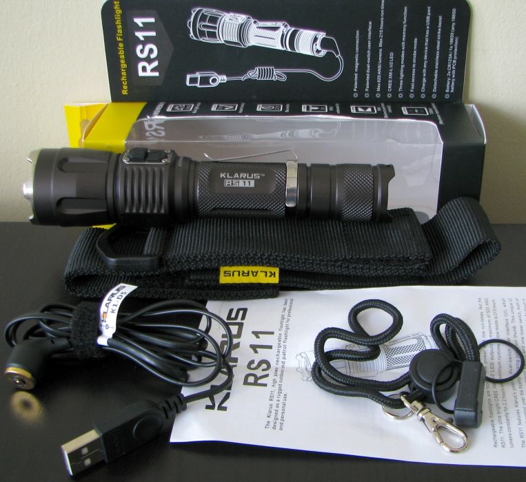
The RS11 uses the new store-shelf display packaging used by Klarus. The light comes with a good number of extras – most notable is the novel magnetic USB charging cable. Also included are the standard manual, spare o-rings, decent wrist strap, pocket clip (attached), and belt holster (with closing flap). Note there is no grip ring included.
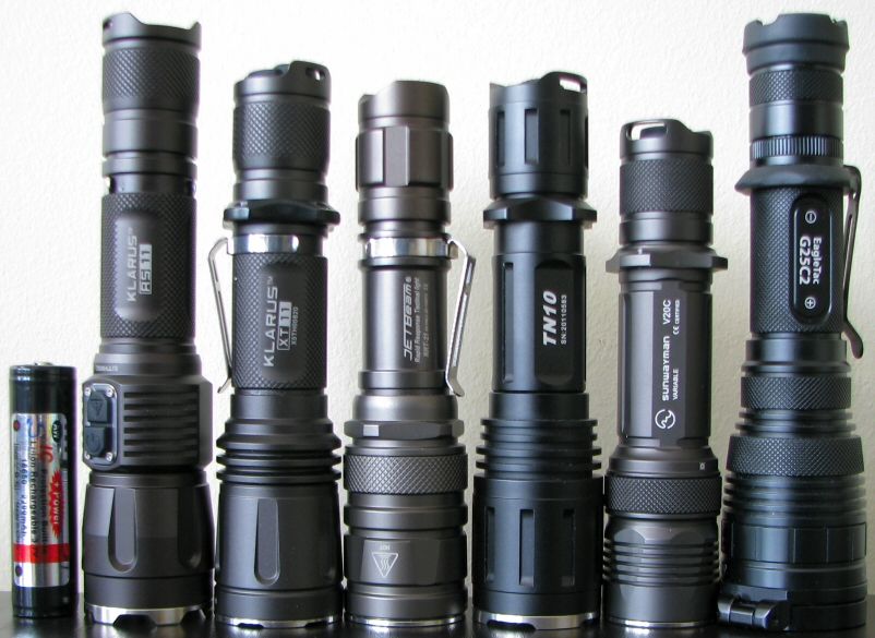
From left to right: AW Protected 18650; Klarus RS11, XT11; Jetbeam RRT-21; Thrunite TN10; Sunwayman V20C; Eagletac G25C2.
Actual Measured Dimensions
All dimensions are personally measured, and given with no batteries installed:
Klarus RS11: Weight 158.0g, Length: 160mm, Width (bezel) 34.9mm
Klarus XT11: Weight 133.0g, Length: 148.8mm, Width (bezel) 35.0mm
JetBeam RRT-21: Weight: 137.3g, Length143.3mm, Width (bezel) 33.8mm
Lumintop TD-15X: Weight 150.3g, Length 147.3mm, Width (bezel): 37.8mm
Thrunite TN10: Weight: 154.7g, Length: 145.5mm, Width (bezel): 35.1mm
Thrunite TN11: Weight: 176.8g, Length: 154.0mm, Width (bezel): 41.0mm
Sunwayman V20C: Weight: 117.4g, Length 133.0mm, Width (bezel) 32.2mm
The RS11 is a little longer than most lights in this category – due to the position of the control switches in the head, and the charging dock in the tail. Overall build is otherwise similar to the XT11 (although the RS11 also has a more aggressive bezel ring).
The anodizing remains a rich dark grey-brown color (type III = HA). As before, no blemishes or flaws on my sample. Labels are not overly bright, but clearly legible against the dark background.
As with the XT-series, knurling is not very aggressive. But with all the ridge detail and extra elements around the head and body, overall grip is good.
As before, the clip-on pocket clip is fairly basic, but seems to hold on fairly well (for this type of clip). And again, the clip is head-facing, and not reversible. There is no grip ring bundled with light (in keeping with the forward switches).
There is a spring in the head, so all flat-top high capacity cells should fit and work fine in the light.
The two truly distinctive aspects of this light the dual-switch control in the head of the light (XT-series lights are in the tailcap), and the 18650 magnetic charging cable for the tail dock.
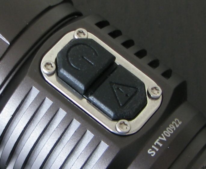
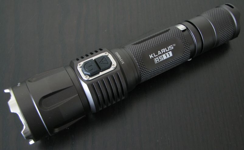
Starting with the switch, you can see the upper on/off switch is raised higher than the lower strobe switch. The interface has of course changed from the XT-series (scroll down for the UI section details). Switch feel is about typical for electronic switches, but the timings may take a little getting used to (again, scroll down to the UI section).
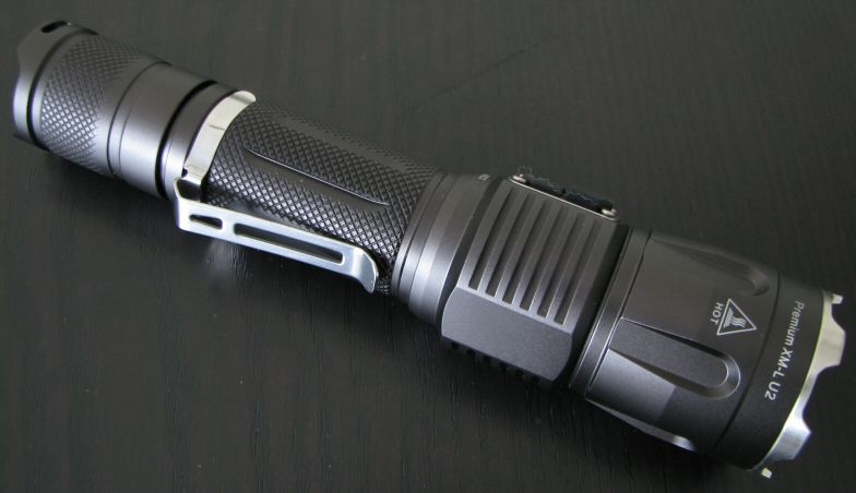
The tail is the other novel area – at the base, you can see two metal circular contacts, and the LED charging status indicator. Inside the tailcap, these contacts are connected to the positive and negative terminals of the battery through the tailcap spring (negative) and internal metal sleeve that is connected to the head (positive). The negative current path is carried by the tail screw threads (which means anodizing is not possible). Note that it is a good idea to keep the tail region of the tailcap clean, as you wouldn't want to inadvertently short the inner metal sleeve to the outer body.
Screw threads appear identical to the XT-series lights, and are traditional triangular-cut. Tailcap threads are not anodized for lock-out (for reasons explained above).
Unlike the XT-series lights, the RS11 can tailstand due to the raised side areas (which are also the lanyard attachment point). However, I found mine still had a slight wobble.
The 18650 charging cable directly attaches to the external tailcap contacts through a strong magnetic connection. However this works, I was not able to read a battery voltage at the external tailcap contacts with an 18650 installed inside the light. This means you apparently don't have to worry about accidentally shorting out a battery inside the light. :thumbsup:
The charging cable itself is another issue. Because of the strong magnetic pull (i.e., the charger head will attach itself to anything made of metal), it is important that you connect the magnetic head to the flashlight BEFORE you connect the USB end to your computer or an AC power adapter.
With the USB end plugged into a computer port or an AC outlet, I can measure an open voltage at the charger head. Should the magnetic contact head of the cable attract a nearby piece of metal, you could potentially short out your USB port (or worse, your AC outlet!). To be fair, there is a raised plastic divider seperating the inner and outer contacts on the charging cable to prevent this from happening. So on a perfectly flat metal surface, you should be fine. But given that the magnet is fairly strong, I wouldn't want to trust that tiny bit of plastic to rule out the potential for even a momentary short. It would certainly cause a nasty incident to your USB/AC port if the contacts were momentary closed by a stray piece of attracted metal. :candle:
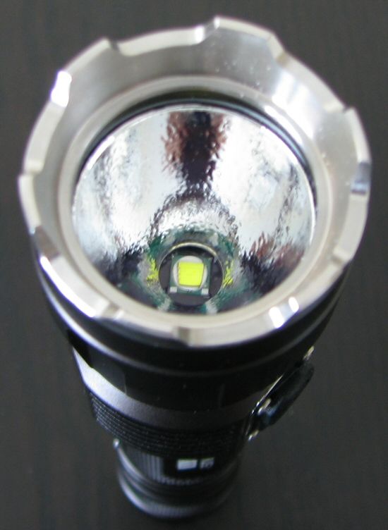
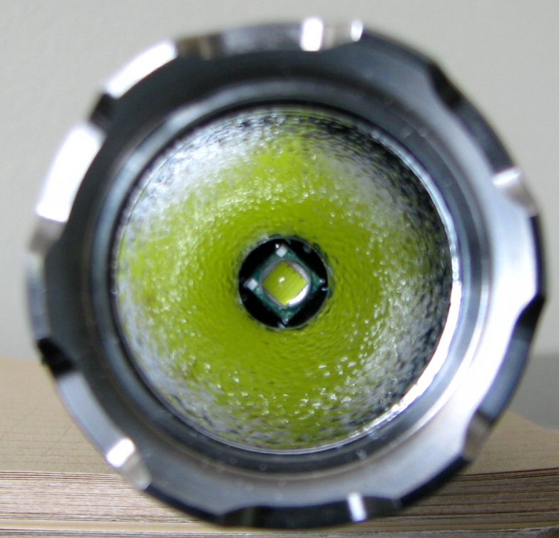
The RS11 seems to use the same reflector as the XT11 (textured Orange Peel finish).
The removable stainless steel bezel ring is now more aggressive than before. I don't know if this is specific for the RS11, or if the XT11 will adopt it as well. The head diameter is unchanged from before, so the colored filters or diffuser available as accessories for the XT11 will work here as well. :twothumbs
User Interface
The user interface has changed considerably from the XT-series lights. In addition to forward placement, both switches are now electronic.
As you would expect, press the upper raised switch (with the power logo) for on-off. You can temporarily press for momentary, press longer for locked-on. The timing here takes some getting used to – despite what the specs say, on my sample you need to hold it for a good 2 secs for it to stay locked-on. That means you could easily signal in Morse code with the momentary feature, but may be a bit frustrating initially for constant-on. :shrug:
You turn the light off by a quick press-release of the on/off switch. You change modes by pressing and holding the on/off switch for >0.6 secs, which will cause the light to jump to the next output mode (and hold at that level). To change output mode again, you have to release the switch and sustain-press once more (i.e., simply holding the switch down will not advance you more than one mode). Mode sequence is Hi > Med > Lo, in a repeating loop on successive presses.
To activate strobe, press and hold the lower switch (with the caution logo). As before, a temporary press will give you momentary mode, a 2+ sec press is required for constant-on strobe.
Unlike the XT-series lights, the RS11 does have a memory mode for constant output levels. But to activate the memory, you have to leave the light on for at least 3 secs in a given mode before turning off. If you turn off faster than that, the light returns to its previously saved level.
For information on the light, including the build and user interface, please see my new video overview:
Video was recorded in 720p, but YouTube typically defaults to 360p. Once the video is running, you can click on the configuration settings icon and select the higher 480p to 720p options. You can also run full-screen.
PWM/Strobe
Lo:
Med:
Hi:
Similar to the XT10/11, the RS11 uses PWM of around 1 kHz (~1.16-1.17 kHz in this case). PWM is an apparently unavoidable by-product of having the dual control circuit. :shrug:
However, there is one significant difference – there is no visual evidence of flicker on the RS11 Hi mode. This is interesting, as there is a clear negative deflection spike on the Hi mode oscilloscope trace, at the same frequency as the lower mode PWM. :thinking:
This may instead be some sort of circuit filtering – it doesn't seem to be PWM, as I am completely unable to see any visual evidence of it (even when shinning on a fan). In contrast, the XT10 and XT11 had noticeable PWM on their respective Hi settings (and a longer duration off-pulse on the oscilloscope trace).
End result is that you don't have to worry about on Hi – the RS11 only has a visible PWM flicker on Lo and Med.
Like with the XT-series lights, I also observed some variable high frequency noise (on the Hi mode in this case). But you will not see any evidence of this visually.
Like the XT10/11, strobe on the RS11 uses the oscillating format popular on "tactical" lights. It is similar to the XT-series, with a strobe frequency that switches between 17.6 Hz and 6.9 Hz every ~1.5 secs. Definitely very annoying, as intended. :green:
Interesting feature that you can directly activate it from off, by pressing the lower button (in both momentary-on, or constant-on).
Charging/Standby drain
The charging dock/cable fully charged a 2200mAh AW protected 18650 in a just over five and half hours. The resting voltage was ~4.17V, which is reasonable and safe for the cell. I don't know if the charger terminates completely once the light goes green, so I recommend you unplug the charger as soon as the charge cycle is completed.
Since both switches are electronic, there needs to be a standby current when the tailcap is fully connected. However, the presence of the charging system in the tailcap must complicate things a little – I wasn't able to get a good reading with my DMM without the tailcap in the current path. :shrug: The XT11 had a low uA current on 18650, which was basically negligible. Hopefully it is comparable on the RS11.
Beamshots:
Time for the white-wall beamshots. All lights are on Max output on an 1x 18650 AW protected cell. Lights are about ~0.75 meter from a white wall (with the camera ~1.25 meters back from the wall). Automatic white balance on the camera, to minimize tint differences.
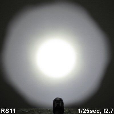
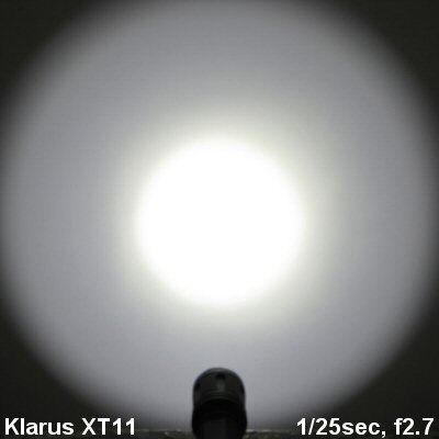
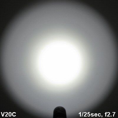
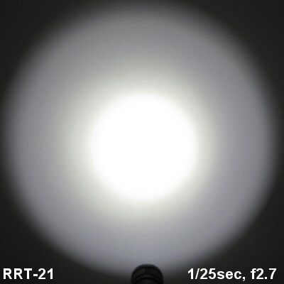
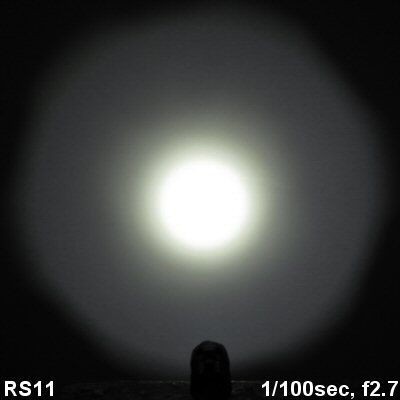
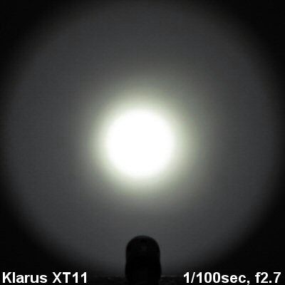
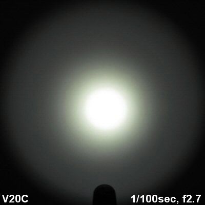
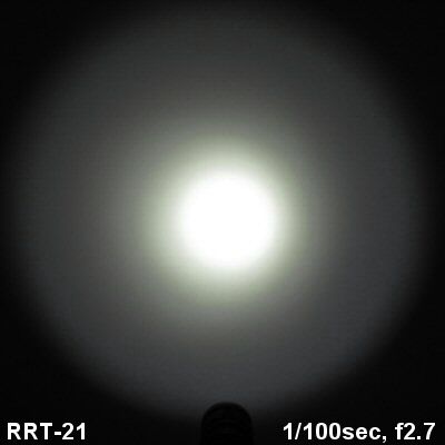
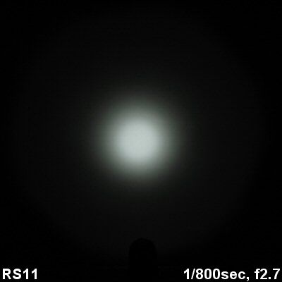
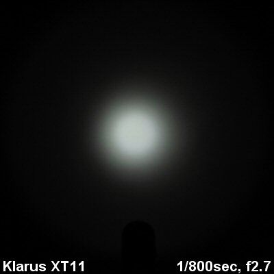
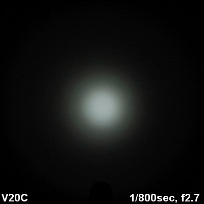
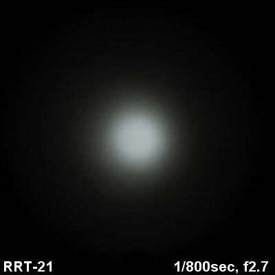
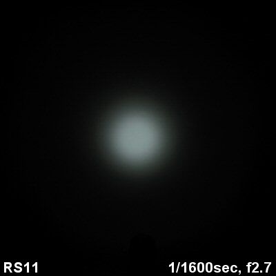
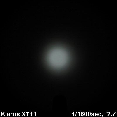
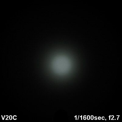
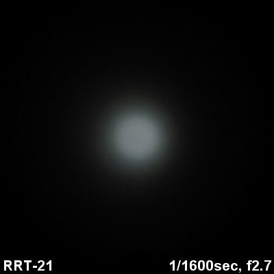
The beam - and max output on 18650 - are very similar to the XT11 (as you would expect from lights that use basically the same head). The only real difference is in the periphery of the spillbeam – due to the more aggressively scalloped bezel, there are some shadow cut-out effects on the RS11, and the overall spillbeam diameter is narrower.
Testing Method:
All my output numbers are relative for my home-made light box setup, a la Quickbeam's flashlightreviews.com method. You can directly compare all my relative output values from different reviews - i.e. an output value of "10" in one graph is the same as "10" in another. All runtimes are done under a cooling fan, except for any extended run Lo/Min modes (i.e. >12 hours) which are done without cooling.
I have devised a method for converting my lightbox relative output values (ROV) to estimated Lumens. See my How to convert Selfbuilt's Lightbox values to Lumens thread for more info.
Throw/Output Summary Chart:
My summary tables are reported in a manner consistent with the ANSI FL-1 standard for flashlight testing. Please see http://www.flashlightreviews.ca/FL1.htm for a discussion, and a description of all the terms used in these tables. Effective July 2012, I have updated all my Peak Intensity/Beam Distance measures with a NIST-certified Extech EA31 lightmeter (orange highlights).
No real surprise here – the output levels and throw of the RS11 are very close to the XT11 (on 1x18650). What you are really getting is the different interface. Note however that my ANSI FL-1 lumen output estimates are lower than the Klarus specs for this light (or the XT11, for that matter).
One significant change is how the RS11 responds to 2x battery sources. On the XT11, output increased considerably on 2xCR123A or 2xRCR, relative to 1x18650. So much so that I had concerns about long-term safety and stability of the light (and batteries) if used extensively this way. I am happy to report the RS11 has the same regulated max output on all battery sources, so should be quite safe (i.e., there's no difference in output on different voltage sources). :thumbsup:
There is some irony here though – the RS11 does not list 2xRCR (16340) under supported batteries (even though the stated voltage range suggests they would be). This is in contrast to the XT11, where they are explicitly supported (but "not recommended"). I am not sure why 2xRCR is not explicitly supported on the RS11, but it is likely to do with the charging solution, which is for 1x18650 only (i.e., it may not be safe to try the charger with RCR installed). Klarus may thus simply being trying avoid any problems from inappropriate battery use and handling.
Output/Runtime Comparison:
The runtime graphs are consistent with what you see in the output tables – the RS11 matches the XT11 for initial output levels on 1x18650, but has lower max output than the XT11 on 2x battery sources.
Also as before the RS11 steps-down on Hi after3 mins (and to a comparable degree)
One difference is on the Med mode and the Hi level after step-down – the RS11 maintains a more regulated output level than the earlier XT11. However, overall efficiency seems to suffer a little for this on the Med level. Certainly, runtime is greatly improved on the Hi mode on 2x battery sources.
Potential Issues
Due to the electronic switches, there will be a stand-by current when fully connected. I was unable to measure this current on my sample, but my previous experience with Klarus lights is that is usually in a negligible low uA range. Unfortunately, you cannot physically lock out the RS11 at the tailcap (i.e., there is no thread anodizing, as the current path runs through the threads).
There is a significant risk of accidental activation when carrying the light, as there is no apparent way to lock out the electronic switches (i.e., no electronic or physical lockout provided).
As with the XT-series lights, the RS11 uses PWM on all modes. However, there is no visual evidence of flickering on the RS11 high mode, and the Lo/Med remains at a reasonable ~1 kHz.
The light uses dual electronic switches, located on the head. Switch timings are somewhat unique, and will take a little getting used to (i.e., you have to hold down the switches longer than typical for constant-on).
Light features a memory mode, but you need to leave the light on for several seconds for the level to be memorized.
Light uses a high-frequency "tactical" strobe, which seems odd for a general purpose light. A slow frequency signaling strobe would be better.
The magnetic charging cable worked well in my testing, with no open voltage reading at the tailcap (i.e., no apparent risk of shorting your battery inside the light). However, there is a potential risk of shorting your USB port (or worse, an AC outlet if using an adapter) if you don't connect the magnetic end of the cable to the light first. Although there is a raised plastic divider on the cable head to seperate the inner and outer ports, the magnetic connector of the cable strongly attracts nearby metal. It could thus potentially short accidentally if you are not careful.
Preliminary Observations
In many ways, the RS11 is basically a revised XT11 intended for a more general purpose (i.e., less "tactical") audience.
Build and circuit-wise, there are a lot of similarities here. But instead of having a physical clicky switch and electronic mode switch on the tail, you have two electronic switches on the head. The switches work somewhat similarly to the XT11 from off - one turns the light on in constant output, the other in strobe. But once on, the UI is quite different – the main switch controls output levels, and responds differently to a temporary or longer-term press.
Personally, I would have preferred it if the switches had actually matched the reported 0.6 sec timings given in the specs – I found the ~2 sec delay for constant-on (vs. momentary-on) rather excessive on my sample. Also, having to press-release repeatedly to change modes is a bit frustrating too. Ditto for having to wait ~3 secs for the light to memorize the level you are on. I presume these timings are dictated by how the circuit functions, but I didn't find them very intuitive.
One thing I do like in the new interface is the memory feature. But of course, I am not a particularly "tactical" guy - Lo and Med modes get a lot more play in my hands. If you want to be guaranteed having max output on activation, stick with the XT11.
Note that there is no way to physically lock-out the light (due to the charging design of the tailcap), and the raised electronic switches pose a significant accidental activation risk.
Aside from the switches, the circuit performance is generally similar to the XT11 (i.e., identical output levels on 18650). But the Lo/Med and step-down Hi output levels are even better regulated now on the RS11 (although seem correspondingly less efficient than the XT11). I am personally glad to see they have adjusted output on 2x battery sources to match the 1x18650 levels now (i.e., on the XT11, 2xCR123A/RCR is quite a bit brighter than 1x18650). Again, if you want that screamingly bright output on 2xRCR, stick with the XT11 – but the RS11 is better balanced for Hi mode runtime and safety on all batteries.
The other novel feature of the RS11 is its unique magnetic charging cable. I quite liked how strong the magnetic connection is – a very straightforward dock, with no fiddling with tiny connectors or rubber plugs. Charging time was reasonable for a USB-based charger, as was the termination voltage for the cell. There is no open voltage at the tailcap, so there is no apparent risk of shorting a cell inside the light. :thumbsup:
However, there is an open voltage on the cable's magnetic dock when it is plugged in at the USB port. Given the strength of the magnet, I feel it is very important you connect the magnetic end to the light BEFORE plugging the USB-end into a port (or AC outlet). Otherwise, the magnetic could accidentally attract metal and short out your USB port (or worse, an AC outlet!). To be fair, there is a raised plastic divider between the contacts on the cable head to prevent this from happening, but I personally am not willing to trust that to prevent even a momentary short (given the strength of the magnet).
Also, please keep in mind that the charging cable is ONLY to be used with 18650. I don't know what would happen if you plugged in to 2xCR123A or RCR, and I don't want to find out. :candle:
All said and done, the RS11 is another option to consider in the general-purpose category of 1x18650, 2xCR123A class lights. I know a lot of people here seem to like the more "tactical" XT11 interface, but there is certainly demand for more traditional consumer interfaces. The question is really whether the various build and design choices here match your needs. :wave:
UPDATE JUNE 5, 2014: I have recently reviewed a revised version of this model for 2014. Please continue all discussion in that thread, thank you.
----
Klarus RS11 provided by goinggear.com for review.
UPDATE JUNE 5, 2014: I have recently reviewed a revised version of this model for 2014. Please continue all discussion in that thread, thank you.
The RS11 is a new light from Klarus. While it shares lot of similarities to the concurrent XT11, there are some significant differences – including the location and operation of the control interface. It also sports a novel charging solution based on a magnetic dock. Let's see how it compares … :wave:
Manufacturer Specifications:
Note: as always, these are only what the manufacturer/dealers report. To see my actual testing results, scroll down the review.
- CREE XM-L (U2) LED
- Lighting modes:
- 620 ANSI lumens (2.2 hrs) -- 150 lumens (7.3 hrs) -- 10 lumens (215 hrs)
- Variable frequency strobe: 620 lumens (4.4 hrs)
- Note: The above-mentioned parameters are approximate and may vary between flashlights, batteries and environments. Lumen data was achieved using 2x CR123 batteries and runtime was achieved using SANYO 18650 2600 mAh lithium ion batteries.
- Working Voltage: 3.4V - 8.4V
- Battery: 2x CR123A / 1x 18650 (any 18650 battery with PCB protection – using unprotected batteries may be hazardous to the user and cause damage to the flashlight)
- Charging: Input: 5 V, Output: 4.2V/500 mA max
- Charging time: Decided by battery capacity. Formula is: Charging time = (battery capacity/500 mA) + 0.5 hrs
- Body color: Military grey
- Reflector: Textured orange peel reflector
- Lens: Toughened ultra-clear glass
- Dimensions: 143mm (Length) x 36 mm (Head) x 25.4mm (Body)
- Net weight: 156g (Excluding battery)
- Included accessories: holster, lanyard, body clip, USB charging cable and one spare o-ring
- Operation:
- Lighting switch: Click the higher button for less than 0.6 of a second to activate momentary-on function. Press and hold the higher button for longer than 0.6 of a second to access the memorized mode (the mode that was previously used). Press and hold the higher button for more than 0.6 of a second to cycle through High-Mid-Low modes and release the switch to select a mode. Click the higher button to turn the light off.
- Strobe switch: Press the lower button for less than 0.6 of a second for momentary strobe. Press and hold the lower button for more than 0.6 of a second to lock the strobe. Click the lower button to return to previous lighting mode.
- Memory function: When the light is on for more than 3 seconds, the mode will be memorized. Turn the light off, then the next time you switch the light on it will activate with the memorized mode.
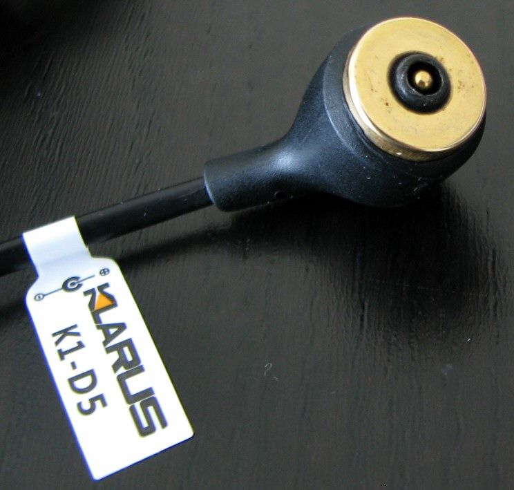
- Charging Operation: RS11 uses special USB charging cable (K1-D5). The USB interface can be used with any USB power supply (including PC USB, vehicle USB, cell phone USB, etc.). The charging cable is connected to the RS11 flashlight with a magnetic connector, which self-locates when the connections are within 1cm of each other. When charging is complete, disconnection can be achieved quickly without damaging the flashlight or cable.
- Charging Indicator: When being charged, the light turns red. When charging is complete the light turns green. No light indicates that there is no load.
- Caution: Charging time should not be more than 24 hours. It is suggested that after the indicator turns green, the charging port should be disconnected within 1 hour.
- Caution: Do not connect or short-circuit the USB charging cable's positive and negative poles with metal products.
- MSRP: ~$117
The RS11 uses the new store-shelf display packaging used by Klarus. The light comes with a good number of extras – most notable is the novel magnetic USB charging cable. Also included are the standard manual, spare o-rings, decent wrist strap, pocket clip (attached), and belt holster (with closing flap). Note there is no grip ring included.
From left to right: AW Protected 18650; Klarus RS11, XT11; Jetbeam RRT-21; Thrunite TN10; Sunwayman V20C; Eagletac G25C2.
Actual Measured Dimensions
All dimensions are personally measured, and given with no batteries installed:
Klarus RS11: Weight 158.0g, Length: 160mm, Width (bezel) 34.9mm
Klarus XT11: Weight 133.0g, Length: 148.8mm, Width (bezel) 35.0mm
JetBeam RRT-21: Weight: 137.3g, Length143.3mm, Width (bezel) 33.8mm
Lumintop TD-15X: Weight 150.3g, Length 147.3mm, Width (bezel): 37.8mm
Thrunite TN10: Weight: 154.7g, Length: 145.5mm, Width (bezel): 35.1mm
Thrunite TN11: Weight: 176.8g, Length: 154.0mm, Width (bezel): 41.0mm
Sunwayman V20C: Weight: 117.4g, Length 133.0mm, Width (bezel) 32.2mm
The RS11 is a little longer than most lights in this category – due to the position of the control switches in the head, and the charging dock in the tail. Overall build is otherwise similar to the XT11 (although the RS11 also has a more aggressive bezel ring).
The anodizing remains a rich dark grey-brown color (type III = HA). As before, no blemishes or flaws on my sample.
Labels are not overly bright, but clearly legible against the dark background. As with the XT-series, knurling is not very aggressive. But with all the ridge detail and extra elements around the head and body, overall grip is good.
As before, the clip-on pocket clip is fairly basic, but seems to hold on fairly well (for this type of clip). And again, the clip is head-facing, and not reversible. There is no grip ring bundled with light (in keeping with the forward switches).
There is a spring in the head, so all flat-top high capacity cells should fit and work fine in the light.
The two truly distinctive aspects of this light the dual-switch control in the head of the light (XT-series lights are in the tailcap), and the 18650 magnetic charging cable for the tail dock.
Starting with the switch, you can see the upper on/off switch is raised higher than the lower strobe switch. The interface has of course changed from the XT-series (scroll down for the UI section details). Switch feel is about typical for electronic switches, but the timings may take a little getting used to (again, scroll down to the UI section).
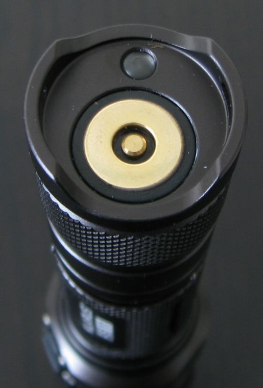
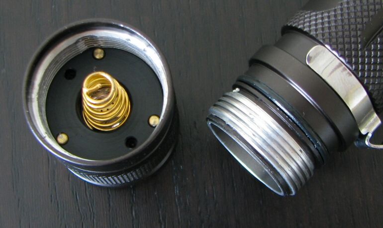
The tail is the other novel area – at the base, you can see two metal circular contacts, and the LED charging status indicator. Inside the tailcap, these contacts are connected to the positive and negative terminals of the battery through the tailcap spring (negative) and internal metal sleeve that is connected to the head (positive). The negative current path is carried by the tail screw threads (which means anodizing is not possible). Note that it is a good idea to keep the tail region of the tailcap clean, as you wouldn't want to inadvertently short the inner metal sleeve to the outer body.
Screw threads appear identical to the XT-series lights, and are traditional triangular-cut. Tailcap threads are not anodized for lock-out (for reasons explained above).
Unlike the XT-series lights, the RS11 can tailstand due to the raised side areas (which are also the lanyard attachment point). However, I found mine still had a slight wobble.
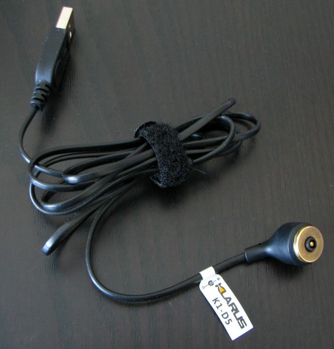
The 18650 charging cable directly attaches to the external tailcap contacts through a strong magnetic connection. However this works, I was not able to read a battery voltage at the external tailcap contacts with an 18650 installed inside the light. This means you apparently don't have to worry about accidentally shorting out a battery inside the light. :thumbsup:
The charging cable itself is another issue.
Because of the strong magnetic pull (i.e., the charger head will attach itself to anything made of metal), it is important that you connect the magnetic head to the flashlight BEFORE you connect the USB end to your computer or an AC power adapter. With the USB end plugged into a computer port or an AC outlet, I can measure an open voltage at the charger head. Should the magnetic contact head of the cable attract a nearby piece of metal, you could potentially short out your USB port (or worse, your AC outlet!). To be fair, there is a raised plastic divider seperating the inner and outer contacts on the charging cable to prevent this from happening. So on a perfectly flat metal surface, you should be fine. But given that the magnet is fairly strong, I wouldn't want to trust that tiny bit of plastic to rule out the potential for even a momentary short. It would certainly cause a nasty incident to your USB/AC port if the contacts were momentary closed by a stray piece of attracted metal. :candle:
The RS11 seems to use the same reflector as the XT11 (textured Orange Peel finish).
The removable stainless steel bezel ring is now more aggressive than before. I don't know if this is specific for the RS11, or if the XT11 will adopt it as well. The head diameter is unchanged from before, so the colored filters or diffuser available as accessories for the XT11 will work here as well. :twothumbs
User Interface
The user interface has changed considerably from the XT-series lights. In addition to forward placement, both switches are now electronic.
As you would expect, press the upper raised switch (with the power logo) for on-off. You can temporarily press for momentary, press longer for locked-on. The timing here takes some getting used to – despite what the specs say, on my sample you need to hold it for a good 2 secs for it to stay locked-on. That means you could easily signal in Morse code with the momentary feature, but may be a bit frustrating initially for constant-on. :shrug:
You turn the light off by a quick press-release of the on/off switch. You change modes by pressing and holding the on/off switch for >0.6 secs, which will cause the light to jump to the next output mode (and hold at that level). To change output mode again, you have to release the switch and sustain-press once more (i.e., simply holding the switch down will not advance you more than one mode). Mode sequence is Hi > Med > Lo, in a repeating loop on successive presses.
To activate strobe, press and hold the lower switch (with the caution logo). As before, a temporary press will give you momentary mode, a 2+ sec press is required for constant-on strobe.
Unlike the XT-series lights, the RS11 does have a memory mode for constant output levels. But to activate the memory, you have to leave the light on for at least 3 secs in a given mode before turning off. If you turn off faster than that, the light returns to its previously saved level.
For information on the light, including the build and user interface, please see my new video overview:
Video was recorded in 720p, but YouTube typically defaults to 360p. Once the video is running, you can click on the configuration settings icon and select the higher 480p to 720p options. You can also run full-screen.
PWM/Strobe
Lo:
Med:
Hi:
Similar to the XT10/11, the RS11 uses PWM of around 1 kHz (~1.16-1.17 kHz in this case). PWM is an apparently unavoidable by-product of having the dual control circuit. :shrug:
However, there is one significant difference – there is no visual evidence of flicker on the RS11 Hi mode. This is interesting, as there is a clear negative deflection spike on the Hi mode oscilloscope trace, at the same frequency as the lower mode PWM. :thinking:
This may instead be some sort of circuit filtering – it doesn't seem to be PWM, as I am completely unable to see any visual evidence of it (even when shinning on a fan). In contrast, the XT10 and XT11 had noticeable PWM on their respective Hi settings (and a longer duration off-pulse on the oscilloscope trace).
End result is that you don't have to worry about on Hi – the RS11 only has a visible PWM flicker on Lo and Med.
Like with the XT-series lights, I also observed some variable high frequency noise (on the Hi mode in this case). But you will not see any evidence of this visually.
Like the XT10/11, strobe on the RS11 uses the oscillating format popular on "tactical" lights. It is similar to the XT-series, with a strobe frequency that switches between 17.6 Hz and 6.9 Hz every ~1.5 secs. Definitely very annoying, as intended. :green:
Interesting feature that you can directly activate it from off, by pressing the lower button (in both momentary-on, or constant-on).
Charging/Standby drain
The charging dock/cable fully charged a 2200mAh AW protected 18650 in a just over five and half hours. The resting voltage was ~4.17V, which is reasonable and safe for the cell. I don't know if the charger terminates completely once the light goes green, so I recommend you unplug the charger as soon as the charge cycle is completed.
Since both switches are electronic, there needs to be a standby current when the tailcap is fully connected. However, the presence of the charging system in the tailcap must complicate things a little – I wasn't able to get a good reading with my DMM without the tailcap in the current path. :shrug: The XT11 had a low uA current on 18650, which was basically negligible. Hopefully it is comparable on the RS11.
Beamshots:
Time for the white-wall beamshots.
All lights are on Max output on an 1x 18650 AW protected cell. Lights are about ~0.75 meter from a white wall (with the camera ~1.25 meters back from the wall). Automatic white balance on the camera, to minimize tint differences.
The beam - and max output on 18650 - are very similar to the XT11 (as you would expect from lights that use basically the same head). The only real difference is in the periphery of the spillbeam – due to the more aggressively scalloped bezel, there are some shadow cut-out effects on the RS11, and the overall spillbeam diameter is narrower.
Testing Method:
All my output numbers are relative for my home-made light box setup, a la Quickbeam's flashlightreviews.com method. You can directly compare all my relative output values from different reviews - i.e. an output value of "10" in one graph is the same as "10" in another. All runtimes are done under a cooling fan, except for any extended run Lo/Min modes (i.e. >12 hours) which are done without cooling.
I have devised a method for converting my lightbox relative output values (ROV) to estimated Lumens. See my How to convert Selfbuilt's Lightbox values to Lumens thread for more info.
Throw/Output Summary Chart:
My summary tables are reported in a manner consistent with the ANSI FL-1 standard for flashlight testing. Please see http://www.flashlightreviews.ca/FL1.htm for a discussion, and a description of all the terms used in these tables. Effective July 2012, I have updated all my Peak Intensity/Beam Distance measures with a NIST-certified Extech EA31 lightmeter (orange highlights).
No real surprise here – the output levels and throw of the RS11 are very close to the XT11 (on 1x18650). What you are really getting is the different interface. Note however that my ANSI FL-1 lumen output estimates are lower than the Klarus specs for this light (or the XT11, for that matter).
One significant change is how the RS11 responds to 2x battery sources. On the XT11, output increased considerably on 2xCR123A or 2xRCR, relative to 1x18650. So much so that I had concerns about long-term safety and stability of the light (and batteries) if used extensively this way. I am happy to report the RS11 has the same regulated max output on all battery sources, so should be quite safe (i.e., there's no difference in output on different voltage sources). :thumbsup:
There is some irony here though – the RS11 does not list 2xRCR (16340) under supported batteries (even though the stated voltage range suggests they would be). This is in contrast to the XT11, where they are explicitly supported (but "not recommended"). I am not sure why 2xRCR is not explicitly supported on the RS11, but it is likely to do with the charging solution, which is for 1x18650 only (i.e., it may not be safe to try the charger with RCR installed). Klarus may thus simply being trying avoid any problems from inappropriate battery use and handling.
Output/Runtime Comparison:
The runtime graphs are consistent with what you see in the output tables – the RS11 matches the XT11 for initial output levels on 1x18650, but has lower max output than the XT11 on 2x battery sources.
Also as before the RS11 steps-down on Hi after3 mins (and to a comparable degree)
One difference is on the Med mode and the Hi level after step-down – the RS11 maintains a more regulated output level than the earlier XT11. However, overall efficiency seems to suffer a little for this on the Med level. Certainly, runtime is greatly improved on the Hi mode on 2x battery sources.
Potential Issues
Due to the electronic switches, there will be a stand-by current when fully connected. I was unable to measure this current on my sample, but my previous experience with Klarus lights is that is usually in a negligible low uA range. Unfortunately, you cannot physically lock out the RS11 at the tailcap (i.e., there is no thread anodizing, as the current path runs through the threads).
There is a significant risk of accidental activation when carrying the light, as there is no apparent way to lock out the electronic switches (i.e., no electronic or physical lockout provided).
As with the XT-series lights, the RS11 uses PWM on all modes. However, there is no visual evidence of flickering on the RS11 high mode, and the Lo/Med remains at a reasonable ~1 kHz.
The light uses dual electronic switches, located on the head. Switch timings are somewhat unique, and will take a little getting used to (i.e., you have to hold down the switches longer than typical for constant-on).
Light features a memory mode, but you need to leave the light on for several seconds for the level to be memorized.
Light uses a high-frequency "tactical" strobe, which seems odd for a general purpose light. A slow frequency signaling strobe would be better.
The magnetic charging cable worked well in my testing, with no open voltage reading at the tailcap (i.e., no apparent risk of shorting your battery inside the light). However, there is a potential risk of shorting your USB port (or worse, an AC outlet if using an adapter) if you don't connect the magnetic end of the cable to the light first. Although there is a raised plastic divider on the cable head to seperate the inner and outer ports, the magnetic connector of the cable strongly attracts nearby metal. It could thus potentially short accidentally if you are not careful.
Preliminary Observations
In many ways, the RS11 is basically a revised XT11 intended for a more general purpose (i.e., less "tactical") audience.
Build and circuit-wise, there are a lot of similarities here. But instead of having a physical clicky switch and electronic mode switch on the tail, you have two electronic switches on the head. The switches work somewhat similarly to the XT11 from off - one turns the light on in constant output, the other in strobe. But once on, the UI is quite different – the main switch controls output levels, and responds differently to a temporary or longer-term press.
Personally, I would have preferred it if the switches had actually matched the reported 0.6 sec timings given in the specs – I found the ~2 sec delay for constant-on (vs. momentary-on) rather excessive on my sample. Also, having to press-release repeatedly to change modes is a bit frustrating too. Ditto for having to wait ~3 secs for the light to memorize the level you are on. I presume these timings are dictated by how the circuit functions, but I didn't find them very intuitive.
One thing I do like in the new interface is the memory feature. But of course, I am not a particularly "tactical" guy
- Lo and Med modes get a lot more play in my hands. If you want to be guaranteed having max output on activation, stick with the XT11.Note that there is no way to physically lock-out the light (due to the charging design of the tailcap), and the raised electronic switches pose a significant accidental activation risk.
Aside from the switches, the circuit performance is generally similar to the XT11 (i.e., identical output levels on 18650). But the Lo/Med and step-down Hi output levels are even better regulated now on the RS11 (although seem correspondingly less efficient than the XT11). I am personally glad to see they have adjusted output on 2x battery sources to match the 1x18650 levels now (i.e., on the XT11, 2xCR123A/RCR is quite a bit brighter than 1x18650). Again, if you want that screamingly bright output on 2xRCR, stick with the XT11 – but the RS11 is better balanced for Hi mode runtime and safety on all batteries.
The other novel feature of the RS11 is its unique magnetic charging cable. I quite liked how strong the magnetic connection is – a very straightforward dock, with no fiddling with tiny connectors or rubber plugs. Charging time was reasonable for a USB-based charger, as was the termination voltage for the cell. There is no open voltage at the tailcap, so there is no apparent risk of shorting a cell inside the light. :thumbsup:
However, there is an open voltage on the cable's magnetic dock when it is plugged in at the USB port. Given the strength of the magnet, I feel it is very important you connect the magnetic end to the light BEFORE plugging the USB-end into a port (or AC outlet). Otherwise, the magnetic could accidentally attract metal and short out your USB port (or worse, an AC outlet!). To be fair, there is a raised plastic divider between the contacts on the cable head to prevent this from happening, but I personally am not willing to trust that to prevent even a momentary short (given the strength of the magnet).
Also, please keep in mind that the charging cable is ONLY to be used with 18650. I don't know what would happen if you plugged in to 2xCR123A or RCR, and I don't want to find out. :candle:
All said and done, the RS11 is another option to consider in the general-purpose category of 1x18650, 2xCR123A class lights. I know a lot of people here seem to like the more "tactical" XT11 interface, but there is certainly demand for more traditional consumer interfaces. The question is really whether the various build and design choices here match your needs. :wave:
UPDATE JUNE 5, 2014: I have recently reviewed a revised version of this model for 2014. Please continue all discussion in that thread, thank you.
----
Klarus RS11 provided by goinggear.com for review.
Last edited:

