
HKJ
Flashaholic
[size=+3]Charger module with TP4056 controller[/size]

Click for larger picture
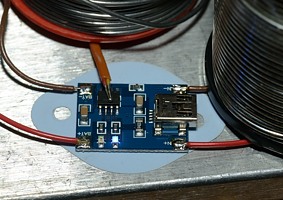
This charger is a very small module for DIY people, it uses the TP4056 controller and standard configuration is with 1A charge current. It does not include any power supply or tray. It did not include any documentation either, just a couple of boards.
The review is about a specific charger module, but any module with the TP4056 will have identical performance.
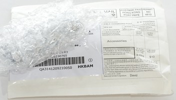
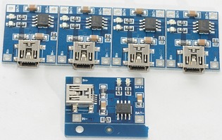
I got it in an envelope with 5 circuits on 2 boards and nothing else. The boards is precut and very easy to break apart.
There is some documentation on the sellers ebay page.
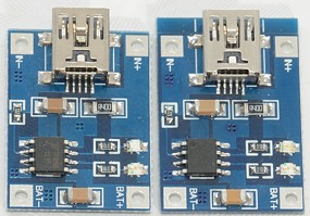
A close study showed that there was a small difference between the size of the boards.
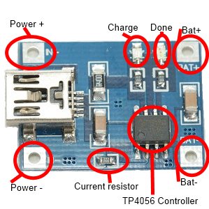
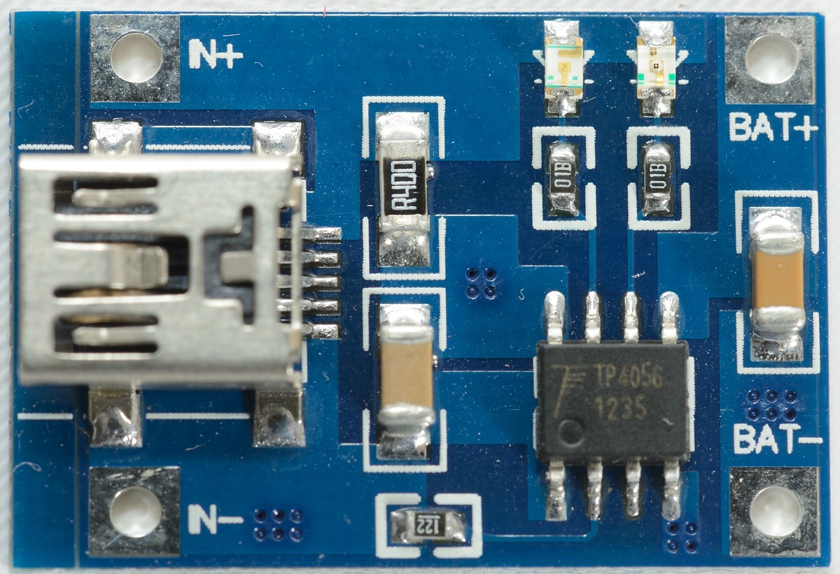
The board needs a 5 volt power supply, this can either be from a mini usb connector or soldered directly to the board.
The "current resistor" can be replaced for other (lower) charge currents, because it is a 0603 size smd resistor (i.e. very small) it can be difficult to replace it.
On my boards I have a blue led for charging and a red led for done.
The charge led will be on when charging and it will be flashing when no battery is connected.
The done led will be on when charging is done or no battery is connected.

The backside of the board has some internal connections and the connections points are also accessible here.
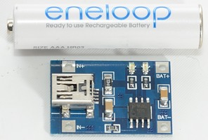
The board is small, the battery is a AAA battery.
With the mounted resistor the charger can handle larger batteries, but changing the resistor makes it to possible to charge smaller batteries.
[size=+2]Measurements[/size]
Below 2.85 volt the charger will charge with about 80mA in 1A configuration (blue led is on).
Above 2.85 volt the charger is applying regular charge current (See curve below).
When charger is disconnected from power, but with a battery in, it will draw below 1uA from the battery.
When the charge current goes below the termination current the charging is stopped and it will charge with around 4 uA.
The charger will restart charging when the cell drops to 4.0 volt.
The charger will not restart after a power loss or battery insertion, except if the battery voltage is below 4.0 volt.
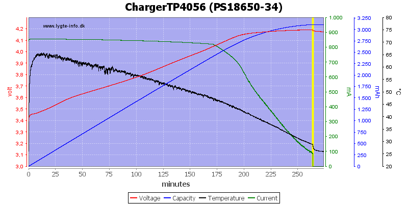
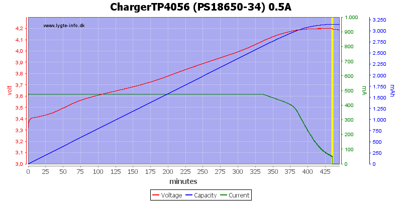
First test is with a 3400mAh battery, the charger does a good CC/CV, except the change from CC to CV is a bit soft, this increase charge time but has no bad effect on the battery. The charger is also a bit below the 1A current, it only charges with 0.85A.
The CV voltage is slightly below 4.2 volt, that is not surprising, because the datasheet for the TP4056 specify that it can be between 4.137 and 4.263 volt. This chip uses 1/10 of the charge current as termination current.
I added a temperature measurement to the test this time, as can be seen the chip heats up fast and then slowly drops in temperature when the battery voltage increases.
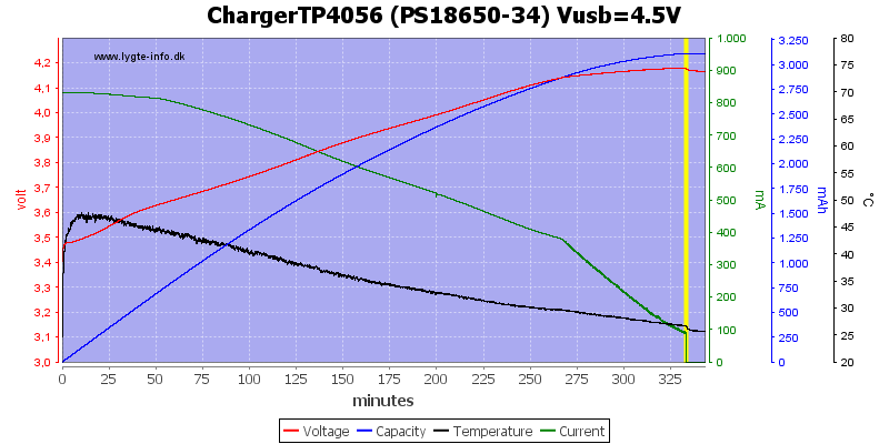
Reducing the supply voltage to 4.5 volt, increases the charge time and reduces the temperature, but the final voltage is slightly lower.
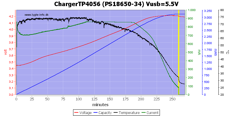
Increasing the voltage does increase the temperature, but also reduces the current. When the chip gets to hot, it reduces the current.
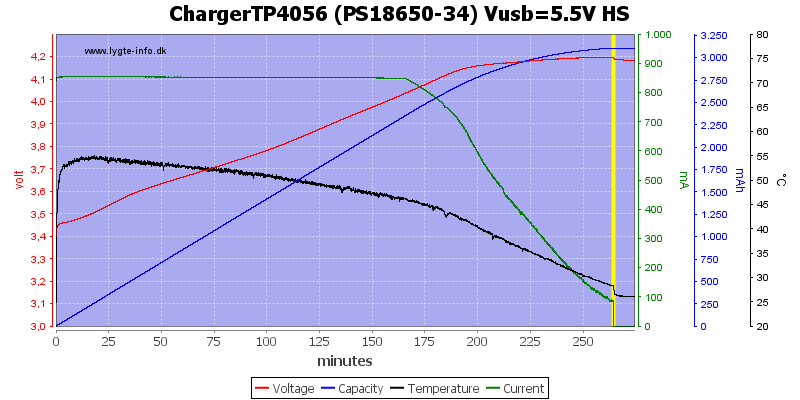
Here I have added a heatsink to keep the temperature down (Remember electric isolation between PCB and heatsink). It works very well, the temperature is lower than with 5.0 volt supply.
The heatsink was just a piece of aluminium under the board with some isolation between.
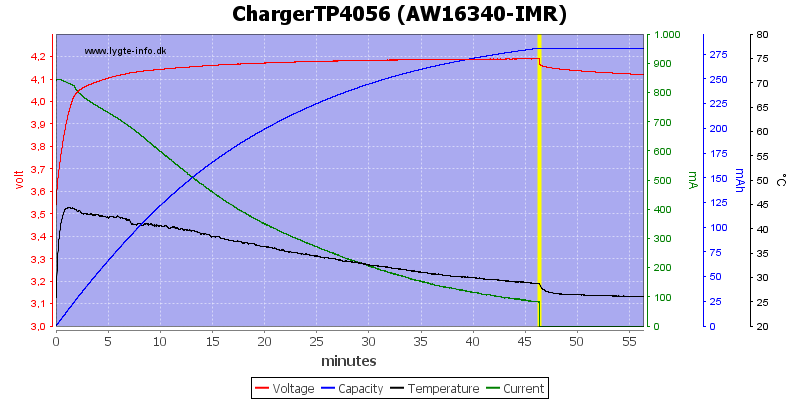
My old 16340 IMR cell is also charged without any problems.
[size=+2]Modified resistor[/size]
Replacing the standard 1.2 kohm resistor with a 2.157 kohm reduces the charge current to 470mA.
The resistor is a 0603 SMD resistor, i.e. it is 1.6 x 0.8 mm.
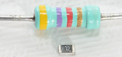
Here a 0603 resistor is placed next to an old style quarter watt resistor.
Again the charger does a CC/CV charging, because the charge current is lower, the termination current is also lower.
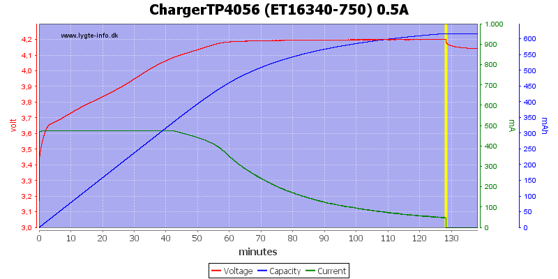
A 16340 battery is a more reasonable size to charge with 0.5A.
Replacing the standard 1.2 kohm resistor with a 4.726 kohm reduces the charge current to 210mA.
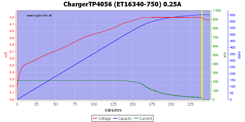
Again I tested with a16340 battery and get a CC/CV curve.
[size=+2]The last and fatal test[/size]
Somebody asked what happen if the battery was connected backwards.
After a fast test I can conclude that it gives smoke and a dead charger module.
[size=+2]Conclusion[/size]
The charger has a good CC/CV profile and can be adapted for many different charge configurations, for multichannel operation it is easy to use multiple board, for smaller batteries the resistor can be replaced. When used at 1A it might be a good idea to mount it on a small heatsink (Remember isolation), to avoid any slowdown in charging and keep the temperature down.
I do not like that it is using a mini usb connector, a micro usb connector would have been better (That is the same as used on phones).
I will call it a good charger for DIY projects.
[size=+3]Notes[/size]
I bought the module on ebay from "1984yht888" where it is called "5pcs Mini 5V USB Interface 1A Charging Board Module Charger For Lithium Battery"
The temperature measurements is not the chip temperature and probably not even the surface temperature of the chip (I believe that the probe is affecting the measurement).
Here is an explanation on how I did the above charge curves: How do I test a charger
Click for larger picture
This charger is a very small module for DIY people, it uses the TP4056 controller and standard configuration is with 1A charge current. It does not include any power supply or tray. It did not include any documentation either, just a couple of boards.
The review is about a specific charger module, but any module with the TP4056 will have identical performance.
I got it in an envelope with 5 circuits on 2 boards and nothing else. The boards is precut and very easy to break apart.
There is some documentation on the sellers ebay page.
A close study showed that there was a small difference between the size of the boards.
The board needs a 5 volt power supply, this can either be from a mini usb connector or soldered directly to the board.
The "current resistor" can be replaced for other (lower) charge currents, because it is a 0603 size smd resistor (i.e. very small) it can be difficult to replace it.
On my boards I have a blue led for charging and a red led for done.
The charge led will be on when charging and it will be flashing when no battery is connected.
The done led will be on when charging is done or no battery is connected.
The backside of the board has some internal connections and the connections points are also accessible here.
The board is small, the battery is a AAA battery.
With the mounted resistor the charger can handle larger batteries, but changing the resistor makes it to possible to charge smaller batteries.
[size=+2]Measurements[/size]
Below 2.85 volt the charger will charge with about 80mA in 1A configuration (blue led is on).
Above 2.85 volt the charger is applying regular charge current (See curve below).
When charger is disconnected from power, but with a battery in, it will draw below 1uA from the battery.
When the charge current goes below the termination current the charging is stopped and it will charge with around 4 uA.
The charger will restart charging when the cell drops to 4.0 volt.
The charger will not restart after a power loss or battery insertion, except if the battery voltage is below 4.0 volt.
First test is with a 3400mAh battery, the charger does a good CC/CV, except the change from CC to CV is a bit soft, this increase charge time but has no bad effect on the battery. The charger is also a bit below the 1A current, it only charges with 0.85A.
The CV voltage is slightly below 4.2 volt, that is not surprising, because the datasheet for the TP4056 specify that it can be between 4.137 and 4.263 volt. This chip uses 1/10 of the charge current as termination current.
I added a temperature measurement to the test this time, as can be seen the chip heats up fast and then slowly drops in temperature when the battery voltage increases.
Reducing the supply voltage to 4.5 volt, increases the charge time and reduces the temperature, but the final voltage is slightly lower.
Increasing the voltage does increase the temperature, but also reduces the current. When the chip gets to hot, it reduces the current.
Here I have added a heatsink to keep the temperature down (Remember electric isolation between PCB and heatsink). It works very well, the temperature is lower than with 5.0 volt supply.
The heatsink was just a piece of aluminium under the board with some isolation between.
My old 16340 IMR cell is also charged without any problems.
[size=+2]Modified resistor[/size]
Replacing the standard 1.2 kohm resistor with a 2.157 kohm reduces the charge current to 470mA.
The resistor is a 0603 SMD resistor, i.e. it is 1.6 x 0.8 mm.
Here a 0603 resistor is placed next to an old style quarter watt resistor.
Again the charger does a CC/CV charging, because the charge current is lower, the termination current is also lower.
A 16340 battery is a more reasonable size to charge with 0.5A.
Replacing the standard 1.2 kohm resistor with a 4.726 kohm reduces the charge current to 210mA.
Again I tested with a16340 battery and get a CC/CV curve.
[size=+2]The last and fatal test[/size]
Somebody asked what happen if the battery was connected backwards.
After a fast test I can conclude that it gives smoke and a dead charger module.
[size=+2]Conclusion[/size]
The charger has a good CC/CV profile and can be adapted for many different charge configurations, for multichannel operation it is easy to use multiple board, for smaller batteries the resistor can be replaced. When used at 1A it might be a good idea to mount it on a small heatsink (Remember isolation), to avoid any slowdown in charging and keep the temperature down.
I do not like that it is using a mini usb connector, a micro usb connector would have been better (That is the same as used on phones).
I will call it a good charger for DIY projects.
[size=+3]Notes[/size]
I bought the module on ebay from "1984yht888" where it is called "5pcs Mini 5V USB Interface 1A Charging Board Module Charger For Lithium Battery"
The temperature measurements is not the chip temperature and probably not even the surface temperature of the chip (I believe that the probe is affecting the measurement).
Here is an explanation on how I did the above charge curves: How do I test a charger
Last edited:
