Designing a new lithium ion battery charger -> suggestions needed

hiuintahs

Flashlight Enthusiast
Joined
Sep 12, 2006
Messages
1,840
Location
Utah
Designing a lithium ion battery charger

Hi guys. I am going to be building a lithium ion battery charger and would like some input on features etc. I've got the schematic about 80% done right now but keep thinking of things to improve it.

Maybe someone might want one if it turns out nice.

Here's what I'm thinking:

1) keep the cost under $20
2) make it simple to use with a few user selectable inputs such as charge current, voltage termination, and start/stop button.
3) no LCD or LED display to have to navigate through
4) want it be able to be used in the vehicle or via solar system (12v) and via USB charging port or computer.
5) want it to be at least 85% efficient
6) want to be able to monitor charge current and battery voltage via external DVM

Now the problem for me is mechanical packaging. The electrical part is the easy part for me as I own the Orcad (Cadence) schematic capture and pcb layout tools. But how to package it.

For my first go round, I am just going to be doing a pcb where the electrical parts are on the bottom side and on the top will be the 12v dc and USB connector, a couple of small tactical feel switches for start/stop and current select and voltage select. Also on the top some surface mount status leds. This pcb then will be the lid or top to a small Bud Industries plastic box that I envision to be about 3.5" x 2" x 1" or larger if I place the 18650 socket rather than an external cradle.

The first pass will be the prototype to get the electronics all working. I'm also using a PIC microcontroller which will be firmware upgradeable as I work through the issues. The DC to DC converter part I should be OK with as that is where more of my background lies.

I'll update this periodically as it evolves but comments welcome.
 
Last edited:

hiuintahs

Flashlight Enthusiast
Joined
Sep 12, 2006
Messages
1,840
Location
Utah
How will you know what charge current you've selected?

My initial thought is to have a little pushbutton switch with momentary action......kind of a tactical feel. Each time the button is pushed it rotates into a different current setting with 3 different choices................say 500ma, 850mA and 1200mA. Three small LEDs indicate which mode you are in........say a green one, yellow one, and a red one. The microcontroller senses the switch transition and turns on a tiny mosfet that shorts out different configurations of a resistor divider.

With the voltage setting, I know some people like to only go to a voltage less than 4.20v. But rather than have a switch for it, I was thinking of having a jumper setting on the pcb kind of like what you see on computer motherboards. You just move the jumper to where you like. And if the setting isn't one that you prefer, then you change out the resistor so that it matches what termination voltage you want.

The nice thing about this is that everything is adjustable. I just need to figure out what the most desirable values are. The buck switching IC I'm planning on using can source a maximum of 3 amps. But I just want to stay about 50% derated for reliability because I don't think I need to provide much heatsink.
 
Last edited:

LEDAdd1ct

Flashlight Enthusiast
Joined
Jul 4, 2007
Messages
3,557
Location
Hudson Valley
Your project sounds interesting.

I'll pop by and read the posts to see how you are progressing.

How will you know what charge current you've selected?
 

psychbeat

Flashlight Enthusiast
Joined
Nov 3, 2009
Messages
2,797
Location
SF norcal
This sounds awesome.
Having a USB output to charge phones etc from the cells would be nice.

Being able to change the termination voltage from 4.1-4.35v would also be amazing.

Some people want to extend a cells life and some new cells have a higher termination voltage.

An enclosed box would be neat for travel etc.
 

Jazzman56

Newly Enlightened
Joined
Dec 18, 2012
Messages
30
Hi Hiuintahs,

If you are measuring from a Digital Multi Meter you will be reading the potential difference put across the cell by the actual charger say 4.2volts. To actually measure the voltage on the cell you must first turn of the charger and then probe for the potential difference. You could have a cycle where it turns off for approx. 10 seconds every 15 min or even better have momentary switch that when pushed puts the charging cycle on pause (turns if off) for 10-15 seconds so that you can accurately measure the cell voltage with a DVM.

Sorry to bother you if you already know this ^^^^

Regards,
Jazzman
 

hiuintahs

Flashlight Enthusiast
Joined
Sep 12, 2006
Messages
1,840
Location
Utah
Thanks for the comments guys. This is just the sort of thing I want to hear.

I have considered puting a 5v charging port on it. The input power would come from the 12v source. It's doable but would necessitate the need to keep power from the battery sockets when in this mode or else would require a separate 12v to 5v regulator circuit.

I really see the need to be able to adjust the termination voltage. Range is what I want to hear and how that is to be done. Would most people just leave it in one setting or would they be changing periodically. I've debated on whether to have that feature as an easy user selectable option or as a jumper on the pcb which would require getting into the box to change? Never-the-less there will be voltage adjustment capability.

I spent a few hours on the internet looking for a small plastic box with a lid. I envisioned having something that was hinged or snapped on and off, but didn't find anything. Saw lots of stuff from China but nothing easy to acquire here in the USA.

As far as measuring the voltages and current with a digital multi meter, my main concern is to just see the progress of the charging and to know that its not being overcharged. The battery does sag just a bit when power is pulled off but not by much. I think the point of looking at the voltage is for most of us here is to just get an assurance that its working the way its suppose to.

For current, I'm passing the charge current through a 0.1 ohm, 0.1% precision resistor and then passing the voltage off of that to an op-amp that gains it up to the proper feedback level to regulate the DC-DC converter. I have a summing junction that compares voltage to this current signal which will keep the unit in constant current (CC) until the feedback voltage reaches the pre-determined setting (4.20v) and then it goes into constant voltage (CV) and the current then tapers off. I'm not sure where the termination should be.............50ma to 100ma? The microcontroller has a 10 bit A-D converter and I will be monitoring the voltage derived off of the current sense resistor. For looking at the current with a multimeter............well, I just gain up the voltage off of the current sense resistor by 10 with an op amp and precision resistors and then you measure voltage that is equivalent to current so no series interruption of the circuit.

Well sorry this is long. It's a fun project for me.
 
Last edited:

LEDAdd1ct

Flashlight Enthusiast
Joined
Jul 4, 2007
Messages
3,557
Location
Hudson Valley
...and then it goes into constant voltage (CV) and the current then tapers off. I'm not sure where the termination should be.............50ma to 100ma?

I am sorry if this is incorrect.

I thought a true CC/CV charger does not cut off at a fixed current; rather, it cuts the flow of current when the current being delivered is 10% of the original.

So instead of cutting off at 50 or 100mA, it would simply cut off at 10% of the original charging current...?

Again, sorry if this is incorrect.
 

HKJ

Flashaholic
Joined
Mar 26, 2008
Messages
9,715
Location
Copenhagen, Denmark
I am sorry if this is incorrect.

I thought a true CC/CV charger does not cut off at a fixed current; rather, it cuts the flow of current when the current being delivered is 10% of the original.

So instead of cutting off at 50 or 100mA, it would simply cut off at 10% of the original charging current...?

Again, sorry if this is incorrect.


A hobby charger will usual stop at 10% of selected charge current, for other chargers it will vary with the programming.

The specifications for LiIon batteries often list the cut off current as 2% to 5% of capacity (Not charge current).
 

hiuintahs

Flashlight Enthusiast
Joined
Sep 12, 2006
Messages
1,840
Location
Utah
LEDAdd1ct, I think you are right. So if a 1amp charge rate is selected, it cuts out at 100mA. 800mA and it cuts out at 80mA, etc. That would be easy to implement since the microcontroller will be reading what the current is at all times. I've seen this method used but don't know the specification yet. It makes sense.

HKJ, I know you've had a lot of experience in this area so keep me straight. 2 to 5% makes sense too. When the termination voltage is reached and the constant current starts to decay it does so rather exponentially and thus slows down the lower it gets. It seems that if you charge at a lower rate to begin with, it might need to go to a lower rate just to get the full charge..........just a thought.
 
Last edited:

HKJ

Flashaholic
Joined
Mar 26, 2008
Messages
9,715
Location
Copenhagen, Denmark
I think you are right. So if a 1amp charge rate is selected, it cuts out at 100mA. 800mA and it cuts out at 80mA, etc. That would be easy to implement since the microcontroller will be reading what the current is at all times. When a charge rate is real low, then the CV period is long as the CC current decays in a longer exponential fashion.............and to get the battery charged all the way would require it sitting on this longer...........thus a lower cut out value when the initial charge value is lower. I'm continually learning.

Yes, it is easy to implement. With my iCharger I can also select a fast charge where it stops at 20% current or a slow charge (I do not remember the limit).

The various cut out current does, of course, affect the capacity of the battery, but only with a small amount.

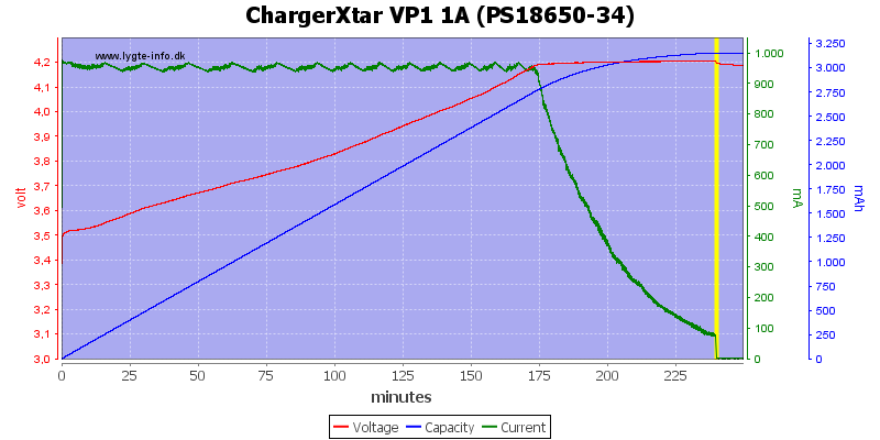
If you look at the curve below you can see that only about 12% of the capacity is charged during the CV phase and that is with a 100mA termination.

ChargerXtar%20VP1%201A%20(PS18650-34).png


I have done some testing with different termination current, but hope to do some more.
 

hiuintahs

Flashlight Enthusiast
Joined
Sep 12, 2006
Messages
1,840
Location
Utah
HKJ, I'm glad to know that the cutoff current value isn't as important. Doing so at 10% of the charge rate looks to be a good number. I typically charge at 800ma to 1000ma on my 3100mah batteries and just terminate the current when in the area of 50ma. That's because I have been using an Agilent E3631A programmable power supply where I set the current limit and voltage output............so it doesn't automatically turn off. I just turn it off when it gets in the ballpark of 50ma. Of course I don't leave it unattended. That is why I need a charger.

Thanks for sharing the graph. Nice to see the amount of capacity that is into the load (battery) by the time the CV phase kicks in. That helps me think that 10% of initial charge rate is good enough.
 

HKJ

Flashaholic
Joined
Mar 26, 2008
Messages
9,715
Location
Copenhagen, Denmark
HKJ, I'm glad to know that the cutoff current value isn't as important. Doing so at 10% of the charge rate looks to be a good number. I typically charge at 800ma to 1000ma on my 3100mah batteries and just terminate the current when in the area of 50ma. That's because I have been using an Agilent E3631A programmable power supply where I set the current limit and voltage output............so it doesn't automatically turn off. I just turn it off when it gets in the ballpark of 50ma. Of course I don't leave it unattended. That is why I need a charger.

There is a reason why nearly every hobby charger uses 10%.

Thanks for sharing the graph. Nice to see the amount of capacity that is into the load (battery) by the time the CV phase kicks in. That helps me think that 10% of initial charge rate is good enough.

You can find many charge curves on my website, each battery test includes one (With a CC/CV that is very close to perfect) and each charger review includes a bunch from that charger.
 

rmteo

Flashlight Enthusiast
Joined
Feb 11, 2009
Messages
1,071
Location
Colorado, USA
I understand your wanting to build a charger. You can get a hobby with the features below for less than $20, so unless it is purely a learning exercise on your part and you are prepared to spend way more than $20 (and many hours of software development/debugging) for a prototype you may want to rethink the project. Microprocessor controlled
Delta-peak sensitivity (NiMH/NiCd)
Individual cell balancing
Li-ion, LiPo and LiFe capable
Ni-Cd and NiMH capable
Large range of charge currents
Store function, allows safe storage current
Time limit function
Input voltage monitoring. (Protects car batteries at the field)
Data storage (Store up to 5 packs in memory)
Battery break in and cycling.Spec.
Input Voltage: 11~18v
Circuit power: Max Charge: 50W / Max Discharge: 5W
Charge Current Range: .1~5.0A
Ni-MH/NiCd cells: 1~15
Li-ion/Poly cells: 1~6
Pb battery voltage: 2~20v
Weight: 170g
Dimensions: 138x75x23mm.
ECO6(2).jpg
 

hiuintahs

Flashlight Enthusiast
Joined
Sep 12, 2006
Messages
1,840
Location
Utah
I understand your wanting to build a charger. You can get a hobby with the features below for less than $20, so unless it is purely a learning exercise on your part and you are prepared to spend way more than $20 (and many hours of software development/debugging) for a prototype you may want to rethink the project.........

Hi rmteo, I appreciate your comments. Ya I recognize that this effort is probably not worth doing from a monetary standpoint. However as primarily an analog engineer, I want to learn the PIC microcontroller. There is nothing like a project that creates motivation.

I'll mention that I have the Bantam BC6-DC which I think the Turnigy is a clone of. What I found out was that it takes 1.6 watts of quescent power, not even charging a battery. I want something more efficient........ie: no LED display. The reason I chose the DC route vs the 120vac route is that I wanted to have a means to charge a 18650 when power goes out. I have a portable power station (52Ah, deep cycle battery) that I use with an 80w portable folding solar panel in the event power goes off for any length of time. I can power other 12v devices like an Engel refrigerator. I just wanted something simple and without having to wade through a menu system. So it might be a futile experiment, but its fun for me.
 
Last edited:

rmteo

Flashlight Enthusiast
Joined
Feb 11, 2009
Messages
1,071
Location
Colorado, USA
The Turnigy (and your Bantam) utilize an LCD (not LED) display. They will consume power (in particular the backlight on the LCD) even when not charging. You can obviously remove the HMI (Human Machine Interface) part but as you have already said you will then need some other means to change current etc. If your intent is to learn PICs (or MCU application development in general), then I would suggest taking a different path - trying to come with a battery charger as your first project will be extremely frustrating. I suggest you hang out at the MCU forums (in particular http://www.microchip.com/forums/search.aspx?searchfor=today). If you intend to use a different development platform (instead of MCHP's MPLAB), then you will want to check out some of the other forums such as http://www.mikroe.com/forum/index.php?sid=9f24d6c5e52a8b884167be2660b2398b.
 

hiuintahs

Flashlight Enthusiast
Joined
Sep 12, 2006
Messages
1,840
Location
Utah
........... If your intent is to learn PICs (or MCU application development in general), then I would suggest taking a different path - trying to come with a battery charger as your first project will be extremely frustrating................

Content deleted.
 
Last edited:

Latest posts

Top