My NiMh battery charger project

paul.allen

Newly Enlightened
Joined
Feb 27, 2013
Messages
62
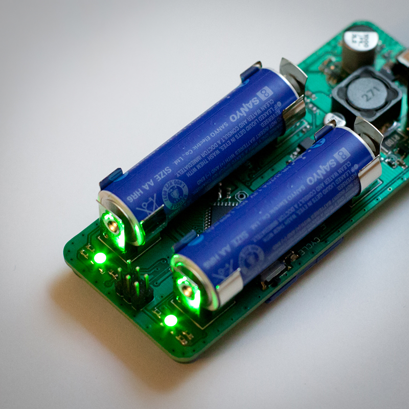
It was suggested to me that I start a dedicated thread for this project. I finished the latest version of my NiMh battery charger. I implemented a few suggestions made by some of you, the main one being switching to solid state caps. Here are some pictures:

4105162.jpg


1708648.jpg


2873738.jpg


There are a few more images on my blog: http://www.paulallenengineering.com/blog.html
 
Last edited:

abhi555

Newly Enlightened
Joined
May 27, 2006
Messages
43
Location
Idaho
Hi Paul, read your blog, its amazing you could do all this in $45.
 

hiuintahs

Flashlight Enthusiast
Joined
Sep 12, 2006
Messages
1,840
Location
Utah
Nice job Paul. I'm doing a similar project for lithium ion. I just ordered the parts from Digikey and Mouser yesterday. I've got the board all layed out, but want to have the parts in hand to double check the pcb footprints. I'll have to share that with you when I get it done. Those battery clips look like Keystone.

How are you doing the battery end charge..........voltage? Is that a microcontroller in the middle and a 6 pin header for in-circuit-programming?

How do you get the board fabricated so cheap.........NRE, photoplots, etc? Did you generate gerber files using software on your computer or did you use one of those on-line type of services? Just curious as to how others do things. Thanks.
 
Last edited:

paul.allen

Newly Enlightened
Joined
Feb 27, 2013
Messages
62
The clips are Keystone. I like them because they partially wrap the batteries when they are clipped in, holding them really nicely. There is an added benefit in that they help conduct heat down to my temperature sensor. And they make a cool clicking noise when you put batteries in or take them out. : )

End of charge detection is based on looking at a combination of voltage (for a negative dip or flat depending on battery temp and impedance), speed of temperature change and max temp, and the impedance of the battery (as a battery charges it's impedance goes up, that is part of the reason why with a constant current you see a rise in voltage. Of Course it is also a battery Charging, so you will see a rise in voltage from that too!!) and a few combinations. I run some test on the batteries before I start charging to try and "guess" their health. Then I make adjustments to everything based on that. For example an older battery will charge hotter than a new one. This will make the change in temperature at the end less dramatic, because it will rise from an already elevated level. Also Older batteries have a higher impedance (that's why they charge hotter) so to deliver the same amount of current during charging, it takes higher voltages. That same high impedance makes them unable to deliver as much current into a given load during a drain. By watching all of it you can tell a lot about the battery during charging and discharging... the trick is balancing it all.

Yes that is the microcontroller in the middle and a 6 pin ISP header. I designed the board and then generated gerbers (most board houses like it if you give them gerbers, but it is amazing how many will do it for you if you have one of a handful of industry standard software packages). I use a local place here in Utah, they have a panel sharing program that helps a Lot with cost. That being said, if you are looking for great quality at an amazing price (and don't mind Purple boards, or waiting) then check out http://dorkbotpdx.org/wiki/pcb_order their new ordering site is http://oshpark.com/. I am not affiliated with them, but I have had them make a few boards for me and was really impressed with the quality for the price!! I just wish they would do a different color.
 

paul.allen

Newly Enlightened
Joined
Feb 27, 2013
Messages
62
Hi Paul, read your blog, its amazing you could do all this in $45.

My first Charger ever (two years ago) was an ambitious 4 battery board that cost me over $100. I have learned my lesson of how to keep cost down and still get what I want (mostly).
 

hiuintahs

Flashlight Enthusiast
Joined
Sep 12, 2006
Messages
1,840
Location
Utah
I think it's Circuit Graphics that does the panel sharing. I've never used them but did talk to them about it once. Thanks for telling me. I'll have to try them out. NRE at QTC is $155. And Precision Technology has a $350 minimum order. I use PT when doing volume though because it comes out less expensive. Still hard to make a product to sell when the PCB on small quantity is so expensive.

I'm impressed with your software that you have in that microcontroller. I'm mostly an analog engineer but with the lithium ion charger I've chosen to learn PIC microcontrollers. My last microcontroller project was a Z8 years ago. I don't think I will struggle too much. I just got my PIC programmer a few days ago and should have some parts to play with in the next day or so.
 

paul.allen

Newly Enlightened
Joined
Feb 27, 2013
Messages
62
hiuintahs I didn't notice (until your last post) you are also in Utah. Yes Circuit Graphics... although I can't wholeheartedly recommend them. They are hit and miss. I put test etch patterns on all of my boards so that when I pick them up i can immediately see how they did. Sometimes it is pretty bad and then other times (like this last time), Amazing. They say they do down to 8mil spacing on their panel sharing, but I often am able to squeeze by smaller. However there has been a few times when they gave me my board and they didn't even hit 8mil at all! This last board was the best I have Ever seen from them though, they hit sub 1mil on my test pattern. If they could keep that up I would use them for everything. When it really counts (for work) I use a place out of Arizona (they flash gold in house and a few other things).
 

uk_caver

Flashlight Enthusiast
Joined
Feb 9, 2007
Messages
1,408
Location
Central UK
Is the voltage measurement done on charge?

I've made some chargers for NiMH packs for caving lights, and for them I did voltage measurements in brief off-charge periods, which seemed to work well but which was rather forced on me anyway - the connectors on the packs couldn't be guaranteed to be free of corrosion (or even mud) so that could have significant effects on impedance for on-charge measurement, and it also seemed easier to measure off-charge since that removed the possibility of noise from charging hampering the measurements. Lacking the ability to easily/reliably measure temperature given an existing 2-wire connection, I programmed multiple termination conditions (quick termination on decent -dV, as well as termination on longer-term 0dV) and that seemed to work well even given relatively low charge rates of around 0.2C.

I'd considered trying to use impedance as some kind of extra source of information but I suspect it could be unreliable in my case, though I do measure and display it on a charger/analyser version I built for my own use, since it does give a pointer to general pack/connector/wiring condition.

The SD card on your charger is a great idea for people who want all the details of exactly what has happened, and I'm sure it was providing really useful information during development.

Thanks for the references re: PCB manufacture - I'm looking to get some driver boards made, and I'll look into the places you mentioned.
 

paul.allen

Newly Enlightened
Joined
Feb 27, 2013
Messages
62
The voltage is measured both during charging and like yours, during a "brief off-charge", or in my case a 1.5 seconds discharge (the actual length of this I am still playing with). The SD card was a Big reason why I made my own charger... I wanted to see Everything that goes on during charging (and discharging). It has really helped in the development, as I have had lots off data to pull from when creating and adjusting charge algorithms, Especially when things would go wrong (yes things do go wrong when you are developing), I could see exactly when and why.
 

paul.allen

Newly Enlightened
Joined
Feb 27, 2013
Messages
62
I wouldn't be opposed to it. My only reservation is that I would need at least 100 people interested... and I just don't know if there is that kind of market for something like this.
 

verge

Newly Enlightened
Joined
May 22, 2005
Messages
67
paul.allen... I'm in for one of your 2-bay or 4-bay nimh charger, whichever comes out first.
 

Power Me Up

Enlightened
Joined
Mar 19, 2007
Messages
634
Location
Brisbane, Australia
What are the maximum/minimum charge & discharge rates? What sort of accuracy are you getting? Are you planning to make the source code for the PIC open source so that others can reprogram it to add extra features? Have you considered a 2V reference so that you could charge and test NiZn cells? Could the micro USB connection be used to communicate with a PC, or is it only for supplying power? For $45 for a 2 cell version, I'd probably take 2 - depending on the answers above. I'd expect that you'd need to charge more than that though unless an increase in volume significantly reduces your costs... Even at a higher price, I'd consider at least one with the right features. Sorry about the lack of formatting - the forum has eaten my paragraph breaks!
 

paul.allen

Newly Enlightened
Joined
Feb 27, 2013
Messages
62
Your responses are very encouraging. I think what I am going to do is put the 2 cell version up, as is, on kickstarter and if things go well, I will use the money I raise to produce the prototypes for my 4 cell version that will add different charge rates, a case, buttons and a color LCD.


Power Me Up, to answer your questions, the discharge rate is set in this version to average about a 5 hour discharge time for most AA batteries (it discharges into a 3.9 ohm resistor). This was chosen because mAh ratings are supposed to be calculated based on a load that will drain a battery in 5 hours. The problem is without knowing the actual capacity of a battery beforehand you can't calculate that load. So a 3.9 ohm resistive load turned out to be a nice average compromise. I did however make sure to use PWM pins for the N-channel fet's that control this load, so that if a different resister was used (which in an earlier version I used a 1.8 ohm) then you could use PWM to vary the discharge rate.


Charge Rate for this one is set at a pulsed 800mA rate. At 50% it averages to a 400mA rate. However this was more so that it could still use USB and not surpass drawing 500mA. I have a 1 Amp USB power supply and in software did test up to a 1.2Amp charge rate. Anything more then this and the inductor starts to get hot.


Accuracy right now is down to a change of 1.8mV minimum. When charging, because of the extra noise combined with filtering and averaging I actually get better than that (if you want to learn more as to why, you can look on the internet or ask me in a message).
For temperature I can detect a change of .18 degree C. I was using a different temperature sensor that gave me more sensitivity with 15mV/degree C, but saved almost a dollar per sensor by going with one that is only 10mV/degree C. It dropped my sensitivity... but not much : )
Current is accurate to within at least 1.8mA (notice a pattern? it's the 1.8V ref combined with a 10bit ADC) again though, because I only take current measurements during charging, I actually tend to get better than that.


As far as software, I have feelings both ways about making the code open source. I have spent hundreds of hours testing my code to make sure it is as robust as I can make it. I have also cycled countless batteries for the same reason. I have no problems with making it open source, so long as no one blamed me if they messed up and ruined something.


Going along with above, if I made the software open source, I would also change things so that you could reprogram and communicate with a PC through the USB.


6319535_orig.jpg
 
Last edited:

uk_caver

Flashlight Enthusiast
Joined
Feb 9, 2007
Messages
1,408
Location
Central UK
For discharge, had you considered using a constant-current driver chip like an AMC7135, possibly with a little extra load resistance to spread heat generation?
One of them could could still be used above a low-side current sense resistor if you're measuring discharge current, to take account of any fluctuations, and at ~350mA they're not far off a 0.2C discharge for 2000mAh cells.

Clearly it's easy to calculate total mAh out even if discharging into a resistor, but having constant discharge current would save anyone having to normalise data from the SD card from constant resistance to constant current.
 

HKJ

Flashaholic
Joined
Mar 26, 2008
Messages
9,715
Location
Copenhagen, Denmark
For discharge, had you considered using a constant-current driver chip like an AMC7135, possibly with a little extra load resistance to spread heat generation?
One of them could could still be used above a low-side current sense resistor if you're measuring discharge current, to take account of any fluctuations, and at ~350mA they're not far off a 0.2C discharge for 2000mAh cells.

Clearly it's easy to calculate total mAh out even if discharging into a resistor, but having constant discharge current would save anyone having to normalise data from the SD card from constant resistance to constant current.

Using a large mos transistor and drive it from a filtered PWM output, makes it possible to do a true adjustable constant current load, this is much better than a AMC7135.
 

uk_caver

Flashlight Enthusiast
Joined
Feb 9, 2007
Messages
1,408
Location
Central UK
That's certainly one way (and essentially what I did in my homemade analyser*), but it does require some kind of supervision/feedback.

(*not quite filtered PWM, but D/A by another means - slow RC circuit on the FET gate, driven by a normally-tristated pin which was only turned on to nudge the voltage up or down as required to keep current constant. That allows driving without hardware PWM but with minimal software intervention. At the expense of slow response, it also allows very fine control through tiny nudges, and response could be speeded up by using a 2-pin drive with 'coarse' and 'fine' resistors.)

In this instance, I was just thinking of simple / cheap / better-than-resistor.
 

Power Me Up

Enlightened
Joined
Mar 19, 2007
Messages
634
Location
Brisbane, Australia
That's not quite as good as I was hoping, but my expectations were probably too high considering the cost and size of the device. I'd still like to get one for around that price - especially if it can be reprogrammed. Let me know when you've got your kickstarter set up!

What's your current thoughts on the charge rate capabilities for the 4 cell version? It'd be good to support you with the 2 cell version just to see what you can do with the 4 cell version - what you've created already looks better made than some commercially made products I've looked at!

One concern with having it connected to a PC via the USB port would be the limited current available - even USB3 is limited to 900mA and I'm not even sure if all of that is available to the pins that a USB2 cable connects to... I suppose you could use a buck circuit since you only need around 2V for charging.
 
Top