
ML-102 v5 Charger Mods: MicroUSB, and coil spring to fit protected cells - Updated
Yesterday my ML-102 18650 charger arrived (HKJ's review Here). This is a neat little charger, which charges a single 18650 from USB, and can also provide USB power via a full-size USB port to charge phones and other devices.
I got the latest version, revision 5, which has a different spring from the one HKJ reviewed. An unfortunate consequence of this is that it doesn't fit protected 18650s, so I knew I was going to mod it. I therefore present:
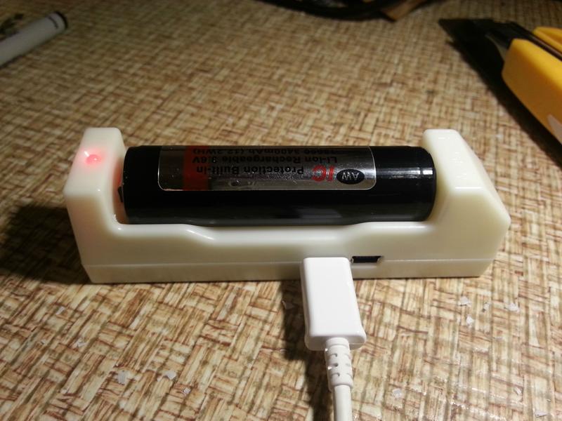
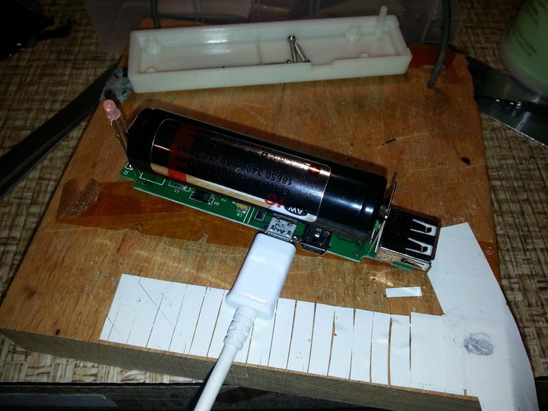
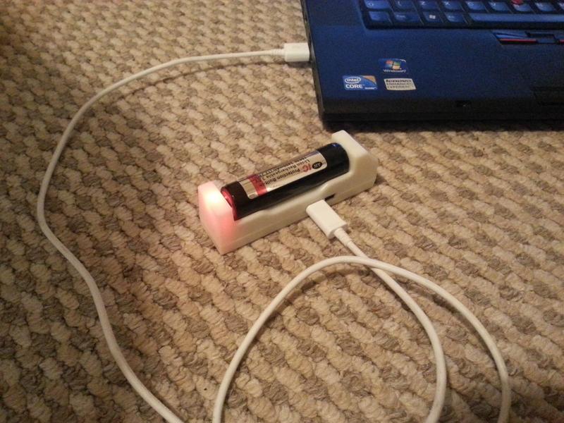
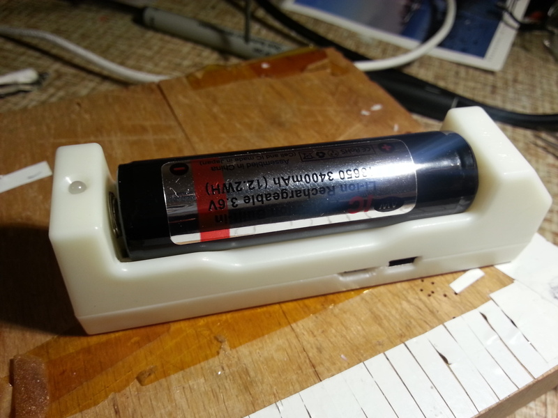
Modded ML-102, charging an AW protected 18650 via MicroUSB!
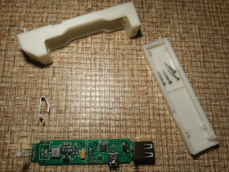
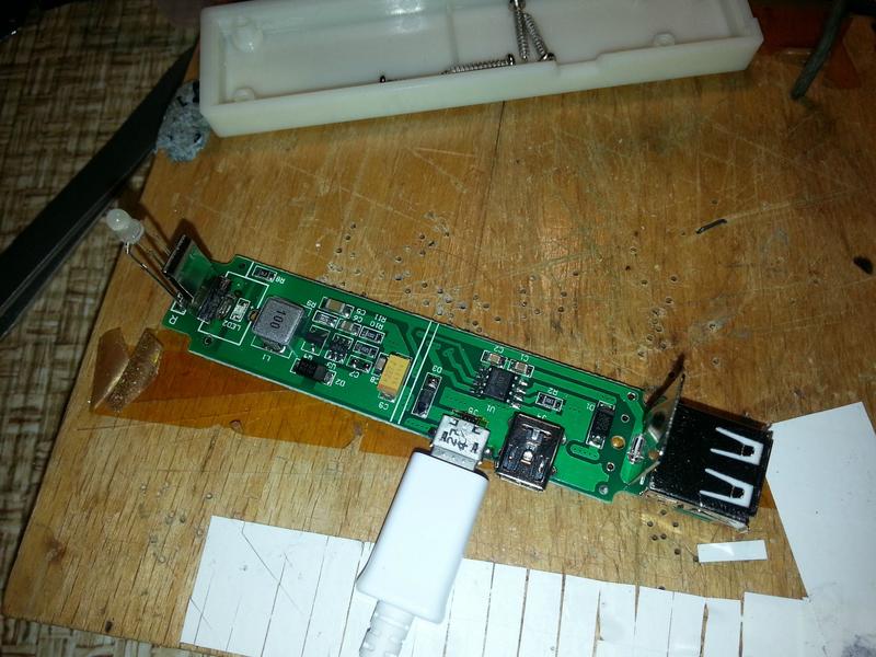
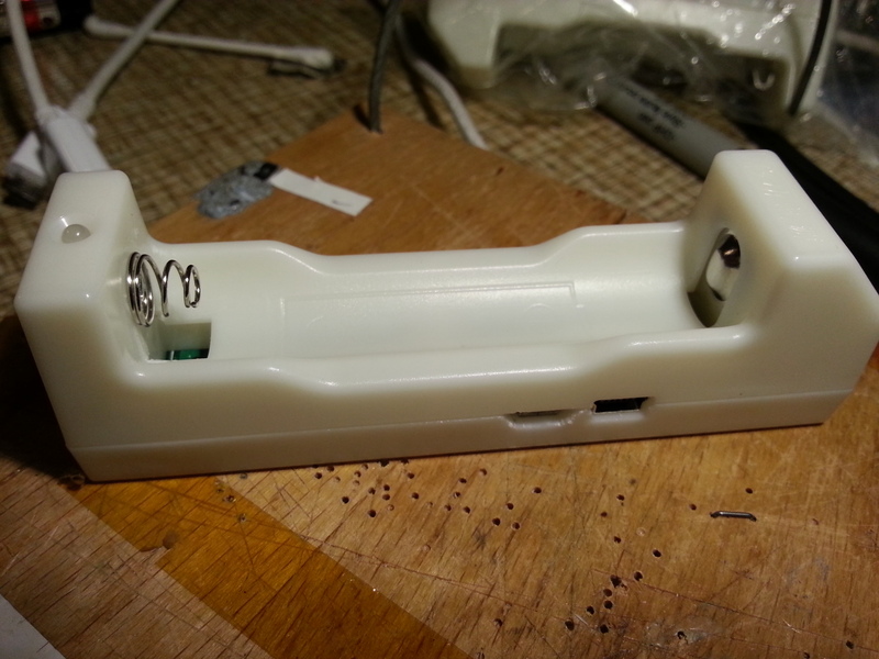
When it arrived, of course the first thing I did was to take it apart :thumbsup:
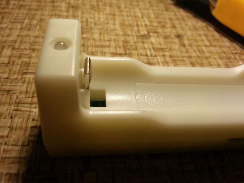
I'd just desoldered the spring to mod it, when something caught my eye:
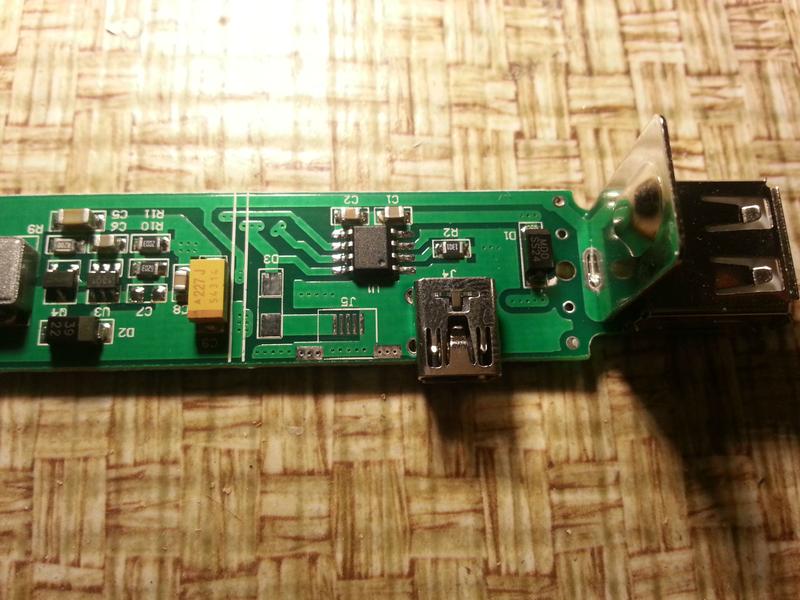
What's that labelled "J5" next to the MiniUSB socket? It looks suspiciously like the footprint of a MicroUSB socket! Well, this might be an unexpected bonus! So I dug out a MicroUSB socket, and placed it on the board...
... looks like a perfect fit! So it seems the manufacturer has heard the pleas for a MicroUSB socket, but hasn't quite got round to fitting it yet.
Sadly, they don't seem to have got the message about the spring...
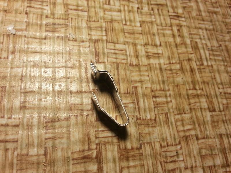
Once desoldered, it becomes obvious that the spring is made of two layers. The outer layer is some kind of nickel-plated contact, but is relatively weak. Behind it is a thicker steel layer, responsible for the strength of the spring. Hmm, I wonder if they come apart...
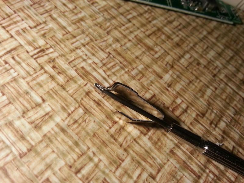
Some prising with a small screwdriver, results in...
Separation. Taking the nickel "contact" layer, and a bit of judicious squeezing with some pliers:
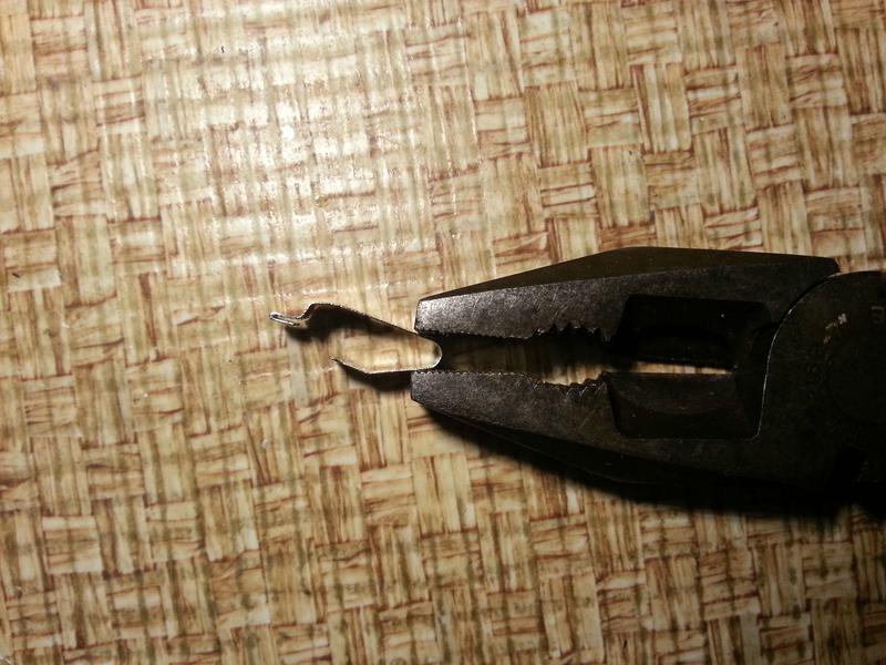
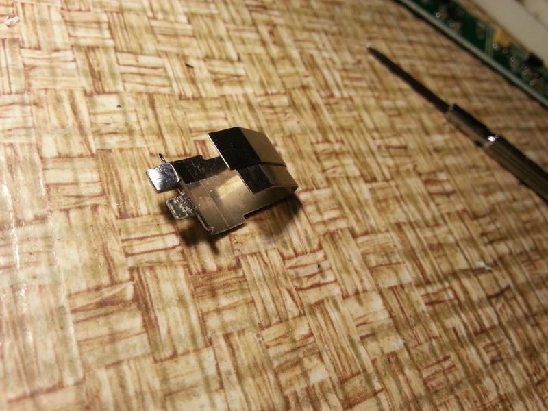
Results in this:
It's not perfect, but it'll do for now, because I'm just itching to get on with that MicroUSB port. The plastic "shoulders" on either side of the metal contact touch the base of my AW 18650 3400 battery, and so inserting it is a bit tricky. Being too hasty (and applying too much force) has resulted in a shallow dent to the positive terminal of one of my batteries, but I think that's avoidable with care. I'm also pretty sure this mod means it won't work to charge shorter, unprotected cells any more, but I haven't got any to test. I only intend to use this charger with these batteries anyway.
Longer-term, I'll probably look at getting a coil spring from somewhere, cutting off the folded over part of the leaf spring, and soldering on the coil spring. That, along with carefully paring down the two plastic shoulders a little bit should do the job properly for any battery.
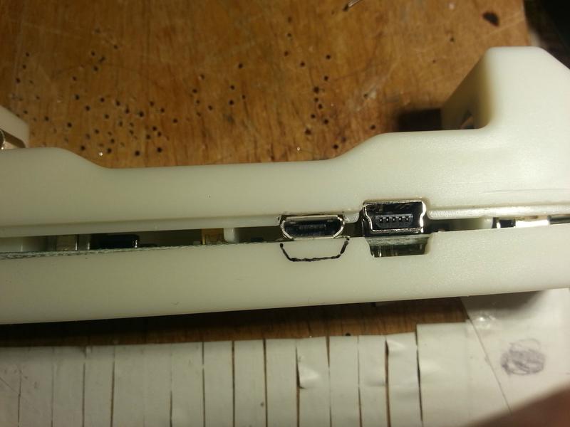
On to the MicroUSB port:
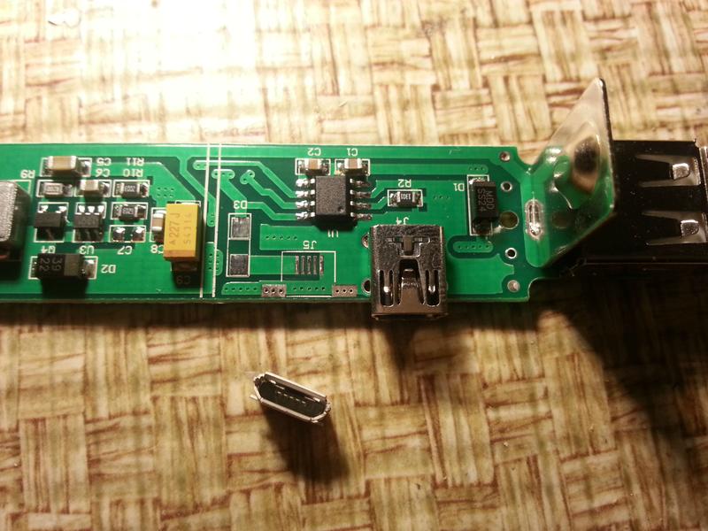
Looking at the PCB tracks, the positive (+5V) pin of the MicroUSB port itself (J5) seems to be connected to an empty space to the left of it, labelled D3. This is a space for a diode to prevent back-flow of power from the charger to the USB port when a battery is inserted. There's a similar arrangement with the MiniUSB port - its diode is labelled D1, near the positive terminal. This means you can plug either or both of the Mini and Micro USB sockets into a supply, and the power won't flow back down either of them where it's not supposed to.
So I'll need to add a diode too. I think I have some of those lying around somewhere.
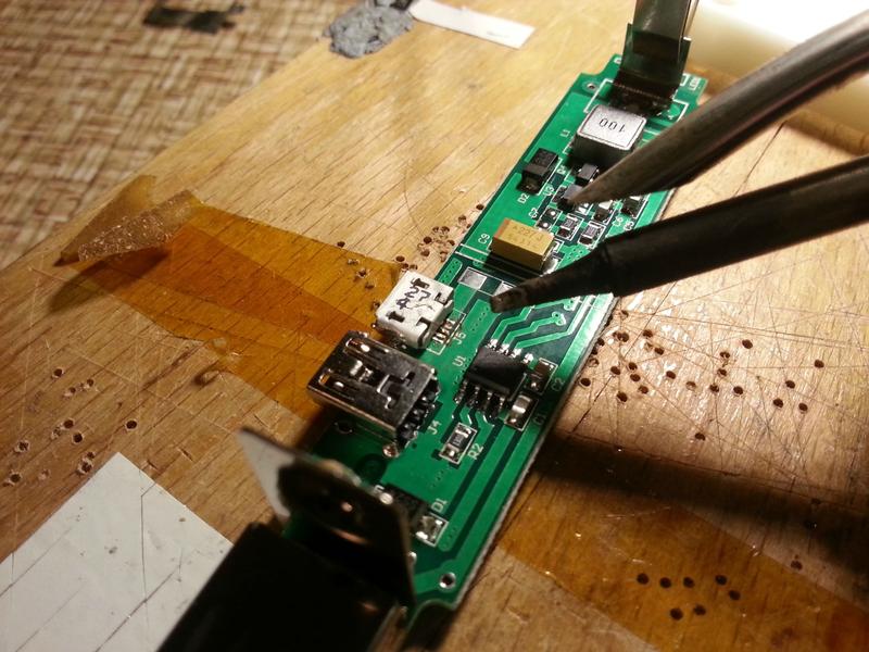
I know most people aren't comfortable with surface-mount soldering, especially those tiny contacts, but there are a couple of things that really help. The first is a hold-down device (block of wood and a bit of bent coathanger) which you can see in the next pic. The other thing is flux. And for removing solder, desoldering wick. With that stuff, you can completely cover those five tiny contacts with a big blob of solder, then suck the excess off with the wick, leaving them perfectly soldered. The PCB mask means they won't bridge, especially if you use flux.
The MicroUSB socket has a couple of "wings" that hold it physically onto the board - you can just see them on the previous pic. Those get soldered to the two silver pads you can see on the board in pic #3. It was a bit tricky to get the soldering iron between the two sockets to solder one of the wings. In retrospect, I should have added a tiny amount of solder (and some flux) to that pad first.
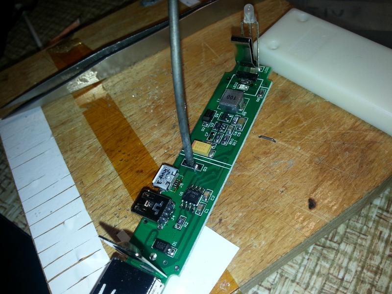
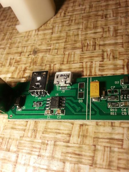
Soldering on the diode. The thick metal rod holding the diode down is a bit of coathanger wire bent into a semicircle. The other end goes into a small hole drilled in the corner of the block of wood. Then the springiness of the wire can be used to hold down SMD parts while you solder them. The stripe on the diode goes next to the D3 lettering, so current can flow away from the socket and into the circuit.
First test! You can't really see with the camera flash, but the LED is lit. Success!
With a battery. The LED is definitely red this time.
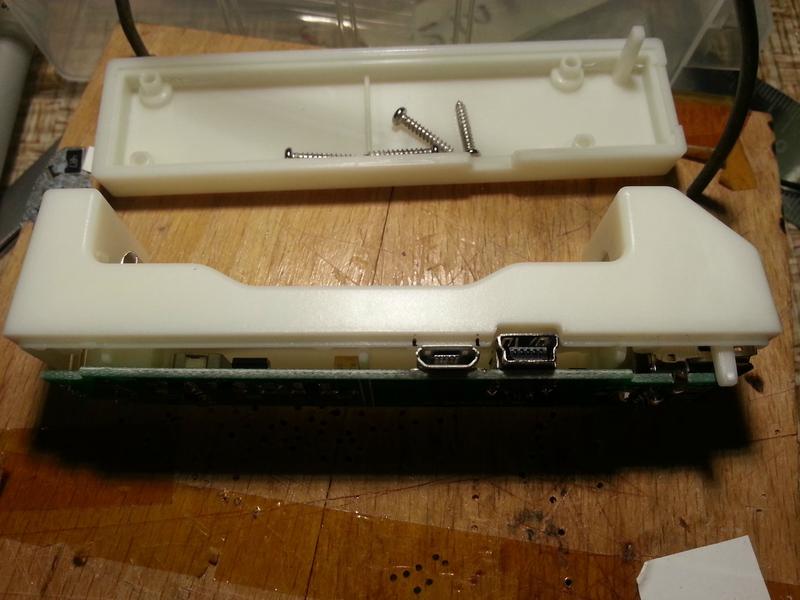
Electronics complete, it's now time to carve a hole in the case for the new socket. I put the top half on as far as it would go, and marked the positions of the edges of the socket with pen.
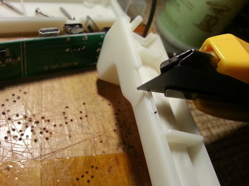
For the top half, you only need to carve as far as the lip on the plastic. I used a stanley knife, but it'd probably be faster with a dremel. My mother's borrowed mine though...
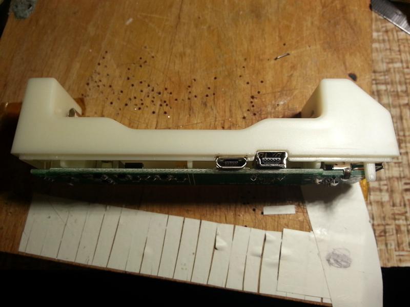
It fits! Now for the bottom half.
Marking out. Ok, roughly eyeballing it and scribbling with a pen...
There was more carving to do this time and the plastic was thicker. Could really have done with that dremel!
It fits!
And it works!
I'm quite happy with this mod so far, although as I mentioned the spring part is a bit rough. I'll have a look at sourcing some coil springs.
I know most people won't be willing to do the SMD soldering. So, if anyone's desperate enough to want the MicroUSB part of the mod, I'll volunteer to do the soldering part for just the price of the components - about $1 -and postage to and from the UK. You can carve your own plastic though! If you want this, please PM me.
I used this MicroUSB socket and some 1.2A Schottky diodes I happened to have. the 1.2A limit is a bit close to the 1A that the charger draws, so if I do any more, I'll get some 2A diodes.
Update, 23 Feb 2014 - Coil Spring
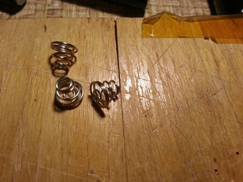
I wasn't happy with the spring arrangement, because it only allows longer, protected cells to be chard. So I wanted to replace it with a coil spring, like prevoius versions of the ML-102. After some searching, I found these springs on ebay, which looked like they would do the trick.
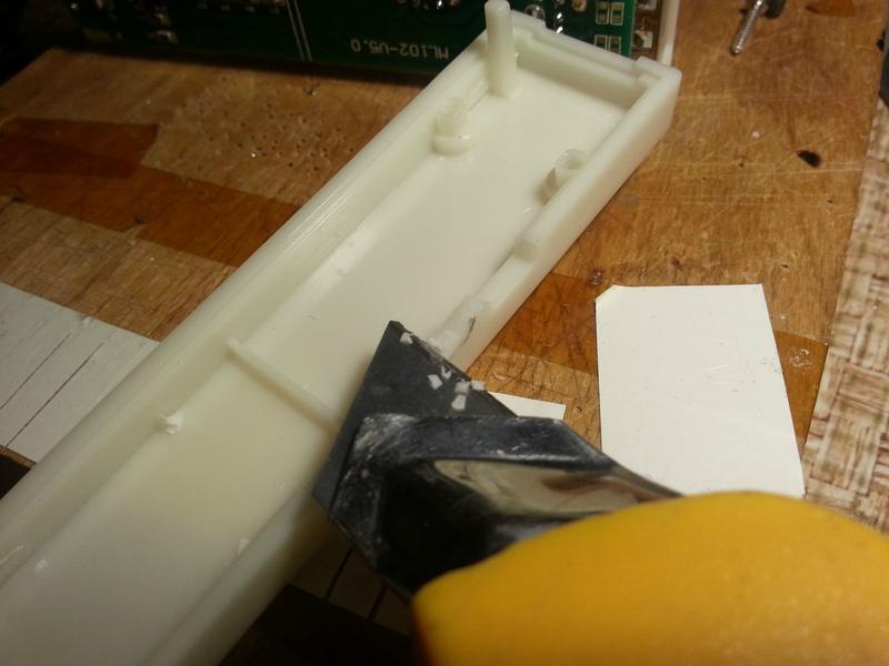
First job was to remove the two plastic ridges at the negative end of the battery compartment, both because they would get in the way of the coil spring, and because if I'd left them, the thickness of the coil spring in addition to the thickness of the ridges would have prevented a protected cell from fitting.
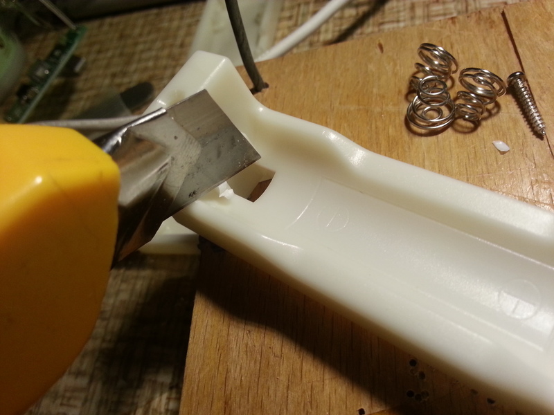
So out came the stanley knife again, and I shaved them off. Heating the knife can make this process easier, but risks burning or browning the plastic.
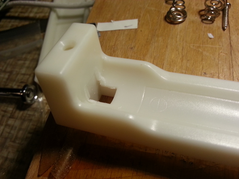
The result of my carving was tolerable but not great, and could have been improved with more patience...
On to the soldering. I was a little concerned that the spring wouldn't take solder very well, because it is nickel-plated steel, but I applied some flux and it soldered just fine. I put just a little blob on the inside of the base of the spring, to have something for the solder on the wire to stick to.
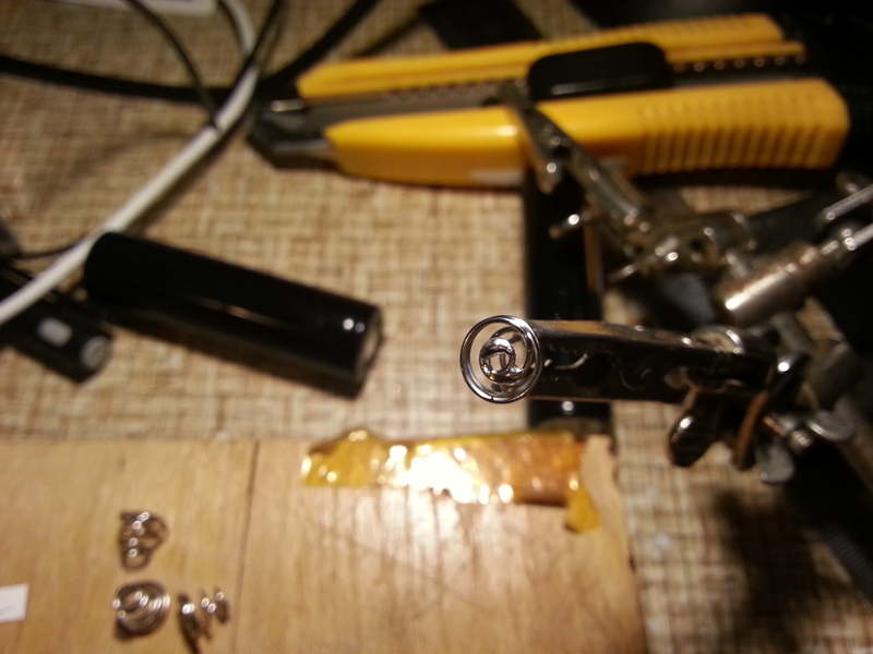
I then desoldered the old negative contact entirely from the board.
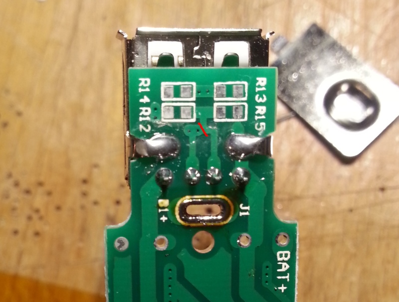
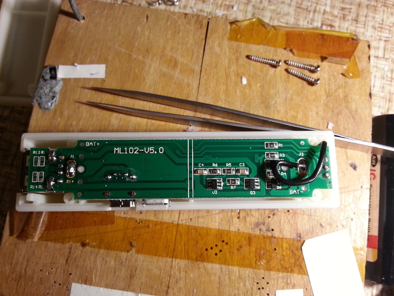
An aside: like a muppet, I first desoldered the positive contact because I wasn't concentrating, and while I was calling myself an idiot, I noticed these blank spaces for resistors underneath the output USB socket. These are to allow configuring the USB port for charging an iPhone (it's currently configured as a USB Dedicated Charger Port - commonly known as "for android"). To do this, you'd need to cut one PCB track where I've marked in red, and then fit resistors of the right values to give the right voltages on the two data pins.
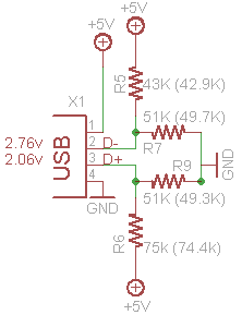
I didn't do this, because all my devices are android, but I found some information here, including this diagram, which shows the correct resistor values. This information is all over the web.
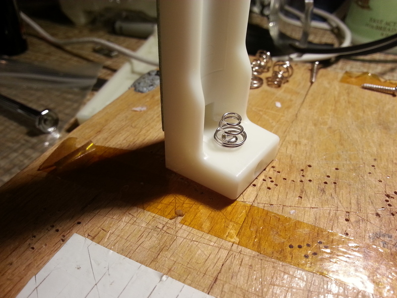
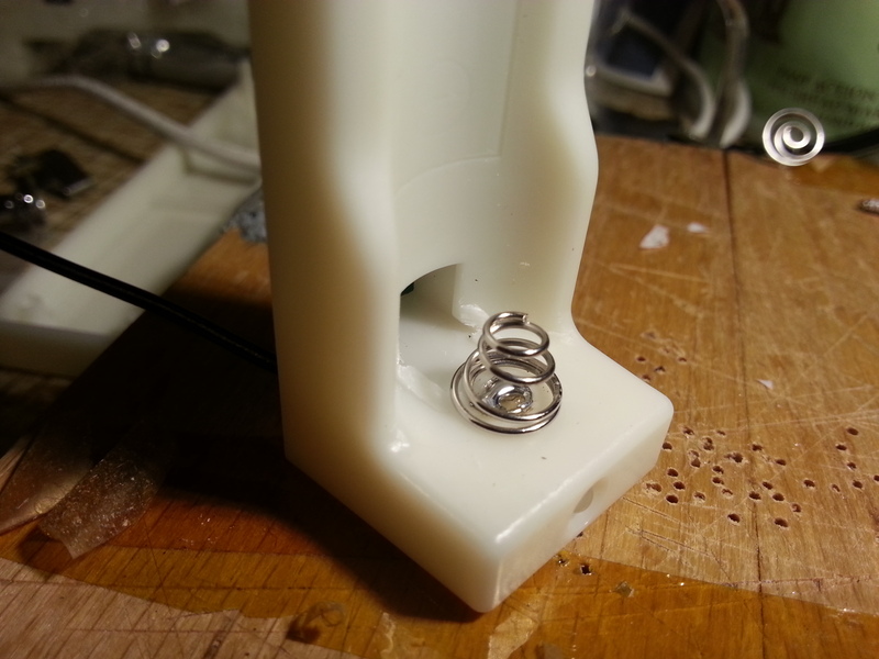
I stood the bottom half of the casing up on its end, and placed the spring as close as I could guess to the centre of where the battery would sit.
I marked the spot, and then with a 1mm PCB drill, I drilled a hole through the plastic for a wire to connect the spring to the PCB. There wasn't room for the electric drill, and I wanted to go slowly anyway, so I turned the drill bit by hand, which was fine for a sharp drill and soft plastic.
Hole drilled, I prepared a short (~5cm) section of wire, and stripped and tinned a very short section of one end - about 2mm. I also bent it 90 degrees, so that when it pokes out of the hole, it doesn't touch the end of the battery when the spring is fully compressed, which would prevent long batteries from fitting.
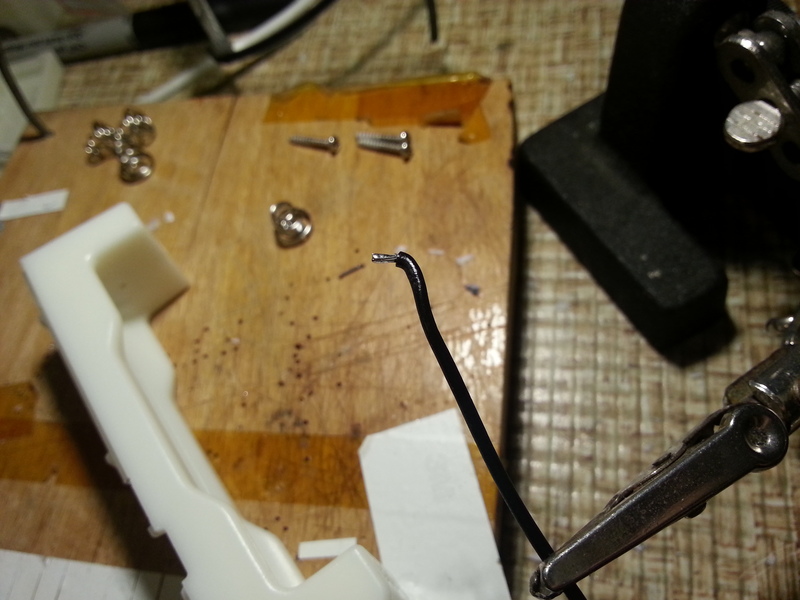
The end of the wire only just protrudes through the hole.
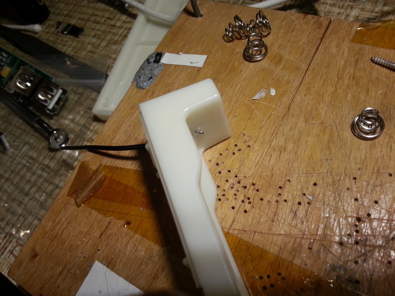
With the spring placed over the top, there's very little overlap.
Actually soldering the wire to the spring was the trickiest part. Not because it didn't take solder very well - it did - but because it was hard to hold the spring in place and get the soldering iron between the coils of the spring and prevent the end of the wire from falling back through the hole. In the end I held a pair of tweezers in one of the crocodile clips of my helping hands, and positioned it so that the weight of the base of the helping hands held the spring down. The crocodile clip and helping hands are just out of shot to the left.
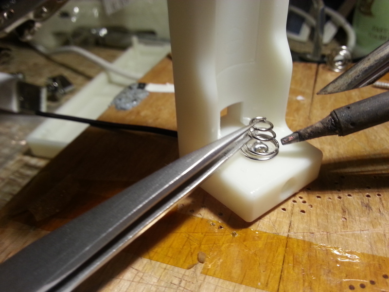
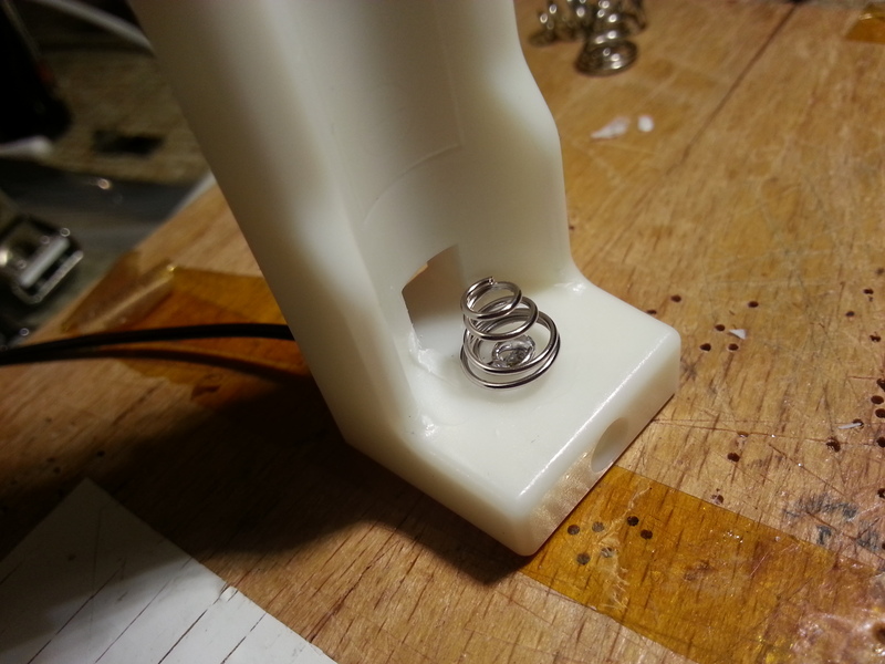
This left me with both hands free to do the actual soldering. As a bonus, the heat from the soldering partially melted the spring into the plastic, so no glue was required to keep it in place. With the difficult part over, it was time for a test fit!
Which worked perfectly. The result looks very neat - I'm not sure I'd be able to do it so neatly a second time though!
The final stage is connecting the wire to the PCB, to the spot where the old negative terminal fitted. I was able to feed the wire up next to one of the screw holes, and loop it round to keep it from moving and blocking the screw hole. I could equally have soldered it to the "BAT-" terminal on the PCB, but I decided to leave that free in case I want to add an external battery socket in the future for charging different sized batteries.
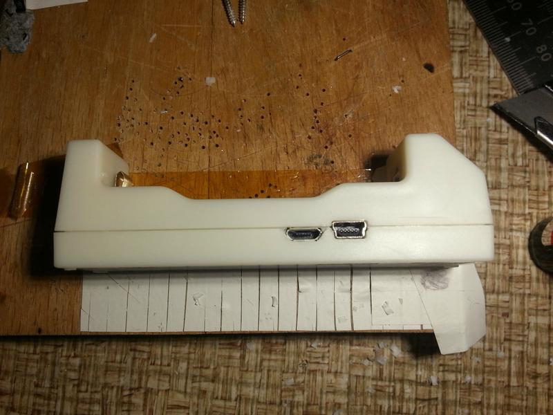
Reassembled:
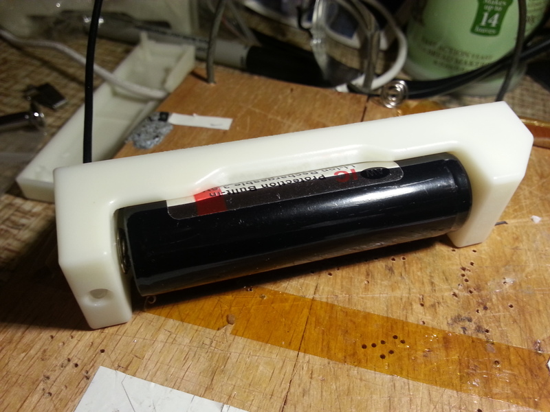
It now happily charges 18650 cells, both protected and unprotected.
Yesterday my ML-102 18650 charger arrived (HKJ's review Here). This is a neat little charger, which charges a single 18650 from USB, and can also provide USB power via a full-size USB port to charge phones and other devices.
I got the latest version, revision 5, which has a different spring from the one HKJ reviewed. An unfortunate consequence of this is that it doesn't fit protected 18650s, so I knew I was going to mod it. I therefore present:
Modded ML-102, charging an AW protected 18650 via MicroUSB!
When it arrived, of course the first thing I did was to take it apart :thumbsup:
I'd just desoldered the spring to mod it, when something caught my eye:
What's that labelled "J5" next to the MiniUSB socket? It looks suspiciously like the footprint of a MicroUSB socket! Well, this might be an unexpected bonus! So I dug out a MicroUSB socket, and placed it on the board...
... looks like a perfect fit! So it seems the manufacturer has heard the pleas for a MicroUSB socket, but hasn't quite got round to fitting it yet.
Sadly, they don't seem to have got the message about the spring...
Once desoldered, it becomes obvious that the spring is made of two layers. The outer layer is some kind of nickel-plated contact, but is relatively weak. Behind it is a thicker steel layer, responsible for the strength of the spring. Hmm, I wonder if they come apart...
Some prising with a small screwdriver, results in...
Separation. Taking the nickel "contact" layer, and a bit of judicious squeezing with some pliers:
Results in this:
It's not perfect, but it'll do for now, because I'm just itching to get on with that MicroUSB port. The plastic "shoulders" on either side of the metal contact touch the base of my AW 18650 3400 battery, and so inserting it is a bit tricky. Being too hasty (and applying too much force) has resulted in a shallow dent to the positive terminal of one of my batteries, but I think that's avoidable with care. I'm also pretty sure this mod means it won't work to charge shorter, unprotected cells any more, but I haven't got any to test. I only intend to use this charger with these batteries anyway.
Longer-term, I'll probably look at getting a coil spring from somewhere, cutting off the folded over part of the leaf spring, and soldering on the coil spring. That, along with carefully paring down the two plastic shoulders a little bit should do the job properly for any battery.
On to the MicroUSB port:
Looking at the PCB tracks, the positive (+5V) pin of the MicroUSB port itself (J5) seems to be connected to an empty space to the left of it, labelled D3. This is a space for a diode to prevent back-flow of power from the charger to the USB port when a battery is inserted. There's a similar arrangement with the MiniUSB port - its diode is labelled D1, near the positive terminal. This means you can plug either or both of the Mini and Micro USB sockets into a supply, and the power won't flow back down either of them where it's not supposed to.
So I'll need to add a diode too. I think I have some of those lying around somewhere.
I know most people aren't comfortable with surface-mount soldering, especially those tiny contacts, but there are a couple of things that really help. The first is a hold-down device (block of wood and a bit of bent coathanger) which you can see in the next pic. The other thing is flux. And for removing solder, desoldering wick. With that stuff, you can completely cover those five tiny contacts with a big blob of solder, then suck the excess off with the wick, leaving them perfectly soldered. The PCB mask means they won't bridge, especially if you use flux.
The MicroUSB socket has a couple of "wings" that hold it physically onto the board - you can just see them on the previous pic. Those get soldered to the two silver pads you can see on the board in pic #3. It was a bit tricky to get the soldering iron between the two sockets to solder one of the wings. In retrospect, I should have added a tiny amount of solder (and some flux) to that pad first.
Soldering on the diode. The thick metal rod holding the diode down is a bit of coathanger wire bent into a semicircle. The other end goes into a small hole drilled in the corner of the block of wood. Then the springiness of the wire can be used to hold down SMD parts while you solder them. The stripe on the diode goes next to the D3 lettering, so current can flow away from the socket and into the circuit.
First test! You can't really see with the camera flash, but the LED is lit. Success!
With a battery. The LED is definitely red this time.
Electronics complete, it's now time to carve a hole in the case for the new socket. I put the top half on as far as it would go, and marked the positions of the edges of the socket with pen.
For the top half, you only need to carve as far as the lip on the plastic. I used a stanley knife, but it'd probably be faster with a dremel. My mother's borrowed mine though...
It fits! Now for the bottom half.
Marking out. Ok, roughly eyeballing it and scribbling with a pen...
There was more carving to do this time and the plastic was thicker. Could really have done with that dremel!
It fits!
And it works!
I'm quite happy with this mod so far, although as I mentioned the spring part is a bit rough. I'll have a look at sourcing some coil springs.
I know most people won't be willing to do the SMD soldering. So, if anyone's desperate enough to want the MicroUSB part of the mod, I'll volunteer to do the soldering part for just the price of the components - about $1 -and postage to and from the UK. You can carve your own plastic though! If you want this, please PM me.
I used this MicroUSB socket and some 1.2A Schottky diodes I happened to have. the 1.2A limit is a bit close to the 1A that the charger draws, so if I do any more, I'll get some 2A diodes.
Update, 23 Feb 2014 - Coil Spring
I wasn't happy with the spring arrangement, because it only allows longer, protected cells to be chard. So I wanted to replace it with a coil spring, like prevoius versions of the ML-102. After some searching, I found these springs on ebay, which looked like they would do the trick.
First job was to remove the two plastic ridges at the negative end of the battery compartment, both because they would get in the way of the coil spring, and because if I'd left them, the thickness of the coil spring in addition to the thickness of the ridges would have prevented a protected cell from fitting.
So out came the stanley knife again, and I shaved them off. Heating the knife can make this process easier, but risks burning or browning the plastic.
The result of my carving was tolerable but not great, and could have been improved with more patience...
On to the soldering. I was a little concerned that the spring wouldn't take solder very well, because it is nickel-plated steel, but I applied some flux and it soldered just fine. I put just a little blob on the inside of the base of the spring, to have something for the solder on the wire to stick to.
I then desoldered the old negative contact entirely from the board.
An aside: like a muppet, I first desoldered the positive contact because I wasn't concentrating, and while I was calling myself an idiot, I noticed these blank spaces for resistors underneath the output USB socket. These are to allow configuring the USB port for charging an iPhone (it's currently configured as a USB Dedicated Charger Port - commonly known as "for android"). To do this, you'd need to cut one PCB track where I've marked in red, and then fit resistors of the right values to give the right voltages on the two data pins.
I didn't do this, because all my devices are android, but I found some information here, including this diagram, which shows the correct resistor values. This information is all over the web.
I stood the bottom half of the casing up on its end, and placed the spring as close as I could guess to the centre of where the battery would sit.
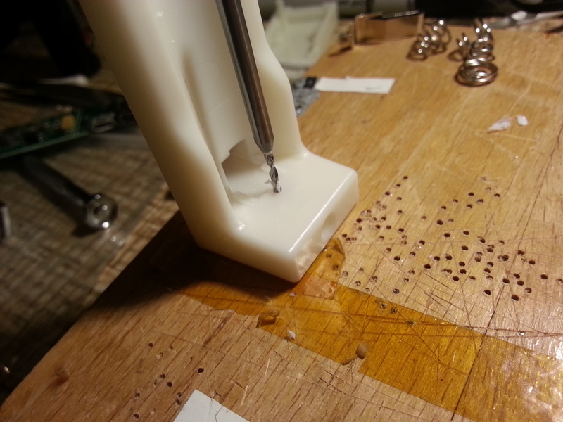
I marked the spot, and then with a 1mm PCB drill, I drilled a hole through the plastic for a wire to connect the spring to the PCB. There wasn't room for the electric drill, and I wanted to go slowly anyway, so I turned the drill bit by hand, which was fine for a sharp drill and soft plastic.
Hole drilled, I prepared a short (~5cm) section of wire, and stripped and tinned a very short section of one end - about 2mm. I also bent it 90 degrees, so that when it pokes out of the hole, it doesn't touch the end of the battery when the spring is fully compressed, which would prevent long batteries from fitting.
The end of the wire only just protrudes through the hole.
With the spring placed over the top, there's very little overlap.
Actually soldering the wire to the spring was the trickiest part. Not because it didn't take solder very well - it did - but because it was hard to hold the spring in place and get the soldering iron between the coils of the spring and prevent the end of the wire from falling back through the hole. In the end I held a pair of tweezers in one of the crocodile clips of my helping hands, and positioned it so that the weight of the base of the helping hands held the spring down. The crocodile clip and helping hands are just out of shot to the left.
This left me with both hands free to do the actual soldering. As a bonus, the heat from the soldering partially melted the spring into the plastic, so no glue was required to keep it in place. With the difficult part over, it was time for a test fit!
Which worked perfectly. The result looks very neat - I'm not sure I'd be able to do it so neatly a second time though!
The final stage is connecting the wire to the PCB, to the spot where the old negative terminal fitted. I was able to feed the wire up next to one of the screw holes, and loop it round to keep it from moving and blocking the screw hole. I could equally have soldered it to the "BAT-" terminal on the PCB, but I decided to leave that free in case I want to add an external battery socket in the future for charging different sized batteries.
Reassembled:
It now happily charges 18650 cells, both protected and unprotected.
Last edited: