Dynamo switching help please

jdp298

Newly Enlightened
Joined
Mar 22, 2011
Messages
115
Location
With your sister, somewhere you wouldn't like
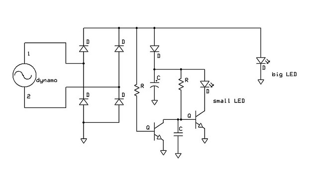
Conceptually, I know exactly what I want to do, but am having trouble designing it/building.

As per some of the fancy German dynamo headlights, I want to switch out the big LED when the wheel stops turning, and switch over to a pair of lower power white ones. With a relay, this would be v.simple, but I don't want to spend the power on driving a relay coil whenever I'm moving.

Turning the big one off and on with an npn transistor makes sense, and if I only do that then I can run the pair of small ones all the time. Thing is, there's no point in that, they'd be lost beside the big one and eating power (however small). I've been toying with the idea of a pnp held shut straight out of the rectifier, and then when that goes quiet, the power in the supercap can pass to the small ones. I'm sure this is achievable without anything with more than 3 pins but I can't nail it down.

Any thoughts?
 

Steve K

Flashlight Enthusiast
Joined
Jun 10, 2002
Messages
2,786
Location
Peoria, IL
I sketched out a schematic that assumes that the small LEDs are powered by a supercap. It's pretty basic....

11685891945_7730f23e42_z_d.jpg


The circuit doesn't include any sort of control of the charging of the supercap, which would be important. There are a lot of things to tweak too, such as the cap on the base of the second NPN transistor. This just helps keep the transistor off during the low voltage portion of the dynamo's AC voltage waveform.
 

jdp298

Newly Enlightened
Joined
Mar 22, 2011
Messages
115
Location
With your sister, somewhere you wouldn't like
Thanks Steve

This is way beyond what I could have 'seen' in my head as the answer. To make sure I understand the concept of operation:

1. When the supercap is charged and the dynamo is 'dark', R1, small LED and Q2. Get that, v. happy.

2. When the dynamo is 'up'. Big LED runs. R1 opens up Q1, which prevents Q2 opening by being a current drain. Guessing R1, R2 are similar values somewhere in the 10k range? What do you envision the leakage, or current wasted is? Can't be much.
 

Steve K

Flashlight Enthusiast
Joined
Jun 10, 2002
Messages
2,786
Location
Peoria, IL
Thanks Steve

This is way beyond what I could have 'seen' in my head as the answer. To make sure I understand the concept of operation:

1. When the supercap is charged and the dynamo is 'dark', R1, small LED and Q2. Get that, v. happy.

with the dynamo stopped, the transistor on the left, Q1, will turn off, and that will let the second transistor, Q2, turn on and let the small LED be powered.


2. When the dynamo is 'up'. Big LED runs. R1 opens up Q1, which prevents Q2 opening by being a current drain. Guessing R1, R2 are similar values somewhere in the 10k range? What do you envision the leakage, or current wasted is? Can't be much.

I hadn't thought too much about resistor sizes. It really depends on how much current you want through the small LED. It wouldn't hurt to add a resistor in series with the small LED, just to limit the current. I'd suggest selecting R2 so that Q2's base current is perhaps 0.04 of the LED current. i.e. if you want 100mA of LED current, shoot for around 4mA of Q2 base current. The size of resistor will also depend on what voltage is on the capacitor.

Have you searched this subforum for info on standlights? There was a really good thread a few years back that covered a lot of different ideas, and had some good solutions to the problem of getting a supercap charged up to the proper voltage and controlling the power level of the standlight. Most of these used two high power LEDs in series, which is a good match for most dynamos, and used one of these LEDs as the standlight.
 

jdp298

Newly Enlightened
Joined
Mar 22, 2011
Messages
115
Location
With your sister, somewhere you wouldn't like
I did see those at the time, I wasn't a member then but read through them. Most of the ideas were very sound but not quite the philosophy I was going for. For example, putting a supercap over the second of 2 high brightness lights was a reasonable idea but all I could get at the time was 1F 5.5V things out of my local supplier. This meant it was either not charging fully or not regulating its output and the LED didn't stay on long enough.

I also decided early on to have 4 separate lights, each with their own rectifier and cct and caps. Turns out my paranoia was well founded as I spent the first 1500 miles having a light failure at least weekly from the bumpy roads, average use of vero-board, single core wires (not doing that again) and sundry other shake rattle and roll issues. Having 4 separate systems meant I was hardly ever without something front and back until I could get home and fix it up again.

<< Caveat -- Thinking out loud here, feel free to correct my misunderstandings >> Now that I've thought about it, I would have expected to see the small Cap on the base of Q1 rather than Q2, which would help hold Q1 open for a bit longer during the low power segment of the dynamo and help prevent flip-flopping. I think the supercap would smooth anything out for the base of Q2, even with the resistor in the way? *OR* Maybe I'd add a smaller supercap (½ a Farad?) straight after the rectifier, then have a 5V regulator (LM317), then split for the big and little LEDs. The 317 would provide a hard cut-off when the input power dropped below a certain threshold which could be smoothed by the first super-(ish) cap?
 

Steve K

Flashlight Enthusiast
Joined
Jun 10, 2002
Messages
2,786
Location
Peoria, IL
The issue of being able to build a reliable light should be separate from what the optimal configuration will be. You should always have a spare light with you, because a failure can always occur. I keep a small light powered by 4 AA nimh cells in my bag.

It would be interesting to put together a list of things needed for a reliable circuit board or light system. As you noted, any wire that can flex should be stranded and not a solid core wire.
Vero board? Is that like perf board?
I build my circuits on copper-clad circuit board. I cut slots in the copper with a dremel tool cut-off wheel in order to create pads and traces. With surface mount parts on the board, I use 30 ga wire-wrap wire to make any extra connections. I then use plasti-dip to hold the wires in place in addition to sealing things up.

You could put the cap on the base of Q1, but since the purpose is to keep Q2 turned off when the dynamo voltage drops to zero during each AC cycle, the Q1-base cap would have to keep Q1 turned on. I'm not sure which location would require a larger cap. The current at Q1's base should be less, so maybe that's a better spot.

You'll have to sketch out schematics for your other ideas... it'd be a lot less ambiguous than a text description.
 

jdp298

Newly Enlightened
Joined
Mar 22, 2011
Messages
115
Location
With your sister, somewhere you wouldn't like
I think I see why you've put the cap on the base of Q2 now. There's no question you see these things differently to how I do. So far you've done almost everything the other way round to how I would have, and probably better for that too. Presume you mean perforation board? If so then vero-board is the same stuff. I've found blu-tac is the final ingredient in making things shock-proof. A fairly stiff gelatinous coloid; solves nearly as many problems as gaffer-tape.

I've only got a Flickr account so you'll have to follow the link where I've tampered with your original circuit. And thanks for your time on this. Don't know anywhere else, even on the broad church that is t'interwebs, where I'd find this kind of assistance.

11736414785_3cf084a946_z.jpg
 
Last edited:

Steve K

Flashlight Enthusiast
Joined
Jun 10, 2002
Messages
2,786
Location
Peoria, IL
I guess my first question should be "what part are you using for your big LED?".

My habit is to use a 3 watt LED, since it can handle the dynamo's output current with no problem. The LED, or LEDs, then serve as a way to limit the dynamo voltage. If you have a single 3 watt LED, then the dynamo output won't go above 3.2v or so (well, that's after the bridge rectifier).

If you are using a single 3 watt LED, then you'll actually want a resistor or diodes where you have your resistor, since that will let you get the voltage up high enough to charge the supercap to the desired voltage.
okay... now I'm scratching my head about the 1/2F cap after the bridge rectifier. It looks like this is a supercap, and the zener is limiting the voltage on it. However... I had designed my circuit to have the supercap near the small LED (just to the left of the small LED).
Are you planning on two supercaps?

Maybe it's time to step back and discuss design requirements. i.e. how many high power LEDs will you be using, what current you plan to go through them, are they wired in series... etc.? And for the standlight, how long do you want it to run, how bright will it be... ? This will help determine how big the supercap will be, whether it should be a low voltage version (2.5v or so) or a high voltage version (5v). Also, how big will this be? Can you fit a big supercap in the design?

Generally speaking, I think my original circuit is pretty good. It does need something to limit the voltage on the supercap. You could use the circuit I use to charge a nimh cell in my headlight....
http://farm9.staticflickr.com/8027/7483782976_bfdfeb28ee_b_d.jpg
It's in the lower left of this schematic. It would require changing the resistors used with the LM4041 to get the desired voltage. Might have to play with R6 too. Or just replace the LM4041 and resistors with a zener diode. The circuit is essentially a voltage limiter. No negative feedback, but functional.
 

jdp298

Newly Enlightened
Joined
Mar 22, 2011
Messages
115
Location
With your sister, somewhere you wouldn't like
First question: Not more than 2½ Watts. I have 2 rear lights off the dynamo, one of then drawing half a Watt (11 x 8mm red LEDs in a motorbike housing), the other only a single 3mm superbright on the mudguard. More likely it'd be planned to draw not more than 1½ Watts as I like having redundancy and other lights. The other front one would be the current design of a 1W white in an old fashioned bullet style headlight and my original rather unsophisticated circuit design inside. Usually mounted on a star PCB, Vf usually around 3.3v, so current to suit the power allocated.

So with that in mind, can one drive a 3W LED at 1½W (restrict the current) and get at least a linear relationship in how much less light comes out?

The first cap after the rectifier is there to smooth the power into the LM317 if that cuts out too easily on the down-cycle of the dynamo at lower speeds (which it might). It could probably be smaller than ½F, but that seems sensible with how quickly they can discharge below 5V when driving a big light. I think this is me trying to work out how I'd stop the thing flip-flopping too easily. Your original placement of the non-super-cap still has me confused, I just can't bend my head around what it's doing and the mechanism by which it holds Q2 shut.

The Small Front Standlight ought to run for about 5 minutes with a good 'be seen by' light. I reckon 1F at 5V ought to do this with a pair of 5mm ultrabrights kind of thing.
 

Steve K

Flashlight Enthusiast
Joined
Jun 10, 2002
Messages
2,786
Location
Peoria, IL
how are the taillights wired up? That's going to affect everything else.

or, to put it another way, do you expect them to be wired in parallel with a regular 6v, 0.5A headlamp?
My habit has been to wire a taillight in series with my headlight, where the taillight is a bunch of red LEDs wired in parallel.
If you want the headlight to have a voltage of 6v, then that'll have to be part of the design specification.

In case it wasn't obvious, I do a lot of design work. It's very important to understand what the design is supposed to do before starting the design.
 

jdp298

Newly Enlightened
Joined
Mar 22, 2011
Messages
115
Location
With your sister, somewhere you wouldn't like
Both taillights are wired in parallel with their own rectifier and standlight circuit. So today I have 4 lights in parallel from the hub, each with their own rectifier and circuits. This was the reliability thing I was going an about. It meant I could isolate out anything that shorted or failed on the road without taking the rest down. It also allowed me to build them 1 at a time and test-adjust without a complete rebuild. Modularity, if you will.

Although the standlights at the front are quite sufficient (each 1W white), I would like one of them to last longer. I could get get more supercaps, there's space, but the idea of switching to longer lasting be-seen lights appeals in this exercise.

At the moment there's a half Watt of spare power floating around, based on the LEDs in use, so dialing down a 3W to 1½W is also appealing if I get the efficiency in light output.
 

Steve K

Flashlight Enthusiast
Joined
Jun 10, 2002
Messages
2,786
Location
Peoria, IL
so what's the output voltage of the dynamo when wired up like this? To get 3W out of the dynamo, you have to get at least 6v out of the dynamo. I'm not sure how you wire up each of those lights and still get 6v across each.

I did add some detail to my schematic, and assumed that the two LED headlights are wired in series. This assumes that each headlight is simply a 3W LED.

11761980775_5e2661c4c7_c_d.jpg
 

jdp298

Newly Enlightened
Joined
Mar 22, 2011
Messages
115
Location
With your sister, somewhere you wouldn't like
Steve

I think you're assuming I know more than I do. Couldn't care less what the output from the dynamo is; mainly because I'm getting my 3.2V across each white LED, therefore I'm getting 1W of light from it. The complete design, which includes redundancy and resilience, 4 separate lights, and other non-LED-related factors, is something I'm quite happy with.

Back on topic, the main reason for this thread was a switching circuit. So back to C2. How does it work to hold Q2 off? I just don't see it. Best I can imagine is that it's working kind of like an integrator, which after a while won't hold Q2 off at all. I'm almost sure that's not right, what am I missing?
 

Steve K

Flashlight Enthusiast
Joined
Jun 10, 2002
Messages
2,786
Location
Peoria, IL
the point of C2 is to keep Q2 off during the low voltage portions of the dynamo's AC voltage waveform. During the high voltage parts of the voltage waveform, Q1 is turned on, which pulls the voltage at Q2's base down to 0.2v or so.

During the low voltage part of the waveform, the voltage won't be enough to keep Q1 turned on. This allows current from R2 to start to charge C2 up. It will take some time for C2 to charge from 0.2 to the 0.6v required for Q2 to start to conduct and turn on the standlight. The goal is that it should take longer to charge up than it takes for the AC waveform to increase again and turn Q1 back on.

That's all there is to it.

as far as not caring what the dynamo voltage is.. it does matter, and if you just connect a white led (and associated bridge rectifier) across the dynamo, you'll only get 4.5v at the dynamo, which won't be enough to turn on a dynamo light designed for 6v. It'll also limit the power out of the dynamo to a total of 2.2W or so.
 

jdp298

Newly Enlightened
Joined
Mar 22, 2011
Messages
115
Location
With your sister, somewhere you wouldn't like
Oh good, thanks for the C2 explanation. Sorry if I miss the trivial from time to time.

All my LEDs run out the back of an LDO, with a 6v5 zener protecting the supercaps between rectifier and LDO. The odd thing is that there's no change in brightness once I get above about 6 or 7 mph all the way past 40. I do get your point about not clamping the dynamo too low, but I think I'm getting away with it through the use of inefficient bridge rectifiers and the like.

It also looks to me like your circuits would work with a MOSFET H-bridge. Is that right?

Finally, and miles from the original question, can you under-drive a 3W and get recognisable efficiency for the power you spend on it?
 

Steve K

Flashlight Enthusiast
Joined
Jun 10, 2002
Messages
2,786
Location
Peoria, IL
regarding a full wave bridge rectifier made of mosfets (which is different from a mosfet H-bridge): you can't have a cap on the output of the mosfet bridge rectifier. The mosfets don't block reverse current. My standlight circuit is isolated from the bridge rectifier, so it won't be affected.

Are you using a resistor between your LDO's and the LEDs? You shouldn't drive LEDs with a voltage regulator. Also, have you reviewed the LDO's datasheet and met all of the criteria for stability? Most LDO's have very specific requirements for the ESR of the output capacitor in order to be stable.
If you are driving the LED with a voltage regulator, or even a current regulator, you shouldn't see any change in the output once you've gotten the input voltage (or current) high enough to meet the desired output. That is when it will be regulating the voltage (or current).

I would recommend reading the datasheet for your LED. It will show you the relationship between current and lumen output.
 

jdp298

Newly Enlightened
Joined
Mar 22, 2011
Messages
115
Location
With your sister, somewhere you wouldn't like
Hmmm, seems I've been a bad human being all this time.

Yes to the resistor, no to the o/p capacitor. The mega-low dropout LDOs from Maplin mention one across input and ground, but as that's where I keep the supercap, I took it out again when a leg broke. That circuit and the other 3 have got through 7000+ miles so far with what is probably a shitty unstable design, but with pretty much never a peep in terms of electrical design. All the problems have been mechanical.

I don't have a new LED to put in, or even know which one I'd choose yet. It was more of a general question as having 2x 1W LEDs has got me (according to the datasheets) 180 lumens vs 250 for the 3W one. It's also the case that 11x 8mm redsuperbrights have a much more dramatic lighting effect than the single ½Watt red star they replaced.
 
Last edited:

Steve K

Flashlight Enthusiast
Joined
Jun 10, 2002
Messages
2,786
Location
Peoria, IL
as a general rule, you do get a small improvement in efficacy/efficiency when driving the LEDs at lower currents. Hard to say if you'll notice it or not, since it takes a rather large change in brightness to be detected.
 

Edocaster

Newly Enlightened
Joined
Mar 27, 2014
Messages
51
I sketched out a schematic that assumes that the small LEDs are powered by a supercap. It's pretty basic....


The circuit doesn't include any sort of control of the charging of the supercap, which would be important. There are a lot of things to tweak too, such as the cap on the base of the second NPN transistor. This just helps keep the transistor off during the low voltage portion of the dynamo's AC voltage waveform.

Hi (first post!) - I recently made a 2x XM-L dynamo light based on http://www.candlepowerforums.com/vb...rcuit-work-)&p=2706860&viewfull=1#post2706860 - complete with that standlight circuit (but with a 68 ohm resistor).

I'm hoping to build a 4x XM-L light soon (based on one of the 'Martin' circuits), and am interested in controlling the standlight by transistors (which I am largely unfamiliar with). A few questions:

- Is the efficiency much better? It irked me that at 0.05A(initially) the basic, passive standlight could lose 0.25W... and it would do this always, including while in motion. Having said that, it works well.
- It seems there is a choice between using one PNP or two NPN (as per your schematic above). Is one way better?
- All these active standlight switching circuits seem to rely on voltage dropping when the wheel stops. But if I'm using a smoothing cap will that cause problems (as it will still be charged up to just below the total Vf of all the LEDs in series)?

I may have misunderstood some basic electrical principles, so apolgies if that's the case!

Thanks.
 

Steve K

Flashlight Enthusiast
Joined
Jun 10, 2002
Messages
2,786
Location
Peoria, IL
Hi (first post!) - I recently made a 2x XM-L dynamo light based on http://www.candlepowerforums.com/vb...rcuit-work-)&p=2706860&viewfull=1#post2706860 - complete with that standlight circuit (but with a 68 ohm resistor).

I'm hoping to build a 4x XM-L light soon (based on one of the 'Martin' circuits), and am interested in controlling the standlight by transistors (which I am largely unfamiliar with). A few questions:

- Is the efficiency much better? It irked me that at 0.05A(initially) the basic, passive standlight could lose 0.25W... and it would do this always, including while in motion. Having said that, it works well.
- It seems there is a choice between using one PNP or two NPN (as per your schematic above). Is one way better?
- All these active standlight switching circuits seem to rely on voltage dropping when the wheel stops. But if I'm using a smoothing cap will that cause problems (as it will still be charged up to just below the total Vf of all the LEDs in series)?

I may have misunderstood some basic electrical principles, so apolgies if that's the case!

Thanks.

regarding efficiency... I'd have to know what two circuits you are comparing. I always liked the simplicity of the standlight design that you linked to. Very basic, not hard for the novice to build and play with. There are some losses in the current limit resistor; about 0.05W for the 150 ohm resistor and diode while the dynamo is running, which is trivial. My main complaint about this sort of design is that it doesn't make good use of the energy stored in the supercap, and the run time is shorter than what I'm used to

one PNP vs two NPNs? I'm assuming that the two NPN's is a reference to the circuit I posted above, but I'm not sure what circuit uses one PNP. As a general rule, I'm in favor of the simpler circuit as long as it meets the functional requirements.

smoothing caps: The smoothing cap doesn't hold up power very long, but the LEDs will essentially turn off and quit drawing current before the cap voltage gets low enough to enable the standlight circuit. Adding a zener diode in series with the base of Q1, along with a reduction in R1 somewhat, might do the job. It would take a little tweaking to figure out the appropriate values.
Personally, I never used smoothing caps, and always thought that the flicker at low speeds would just make me more visible to traffic. :)
 
Top