voltage-current relationship of LED dynamo headlights?

Steve K

Flashlight Enthusiast
Joined
Jun 10, 2002
Messages
2,786
Location
Peoria, IL
I haven't bought a commercial LED dynamo headlight (have always made my own). When I hear people ask questions about tweaking the LED headlight setup, I can't offer any support because I don't know what the headlight does. Specifically, I'm wondering about the input impedance of the light. i.e. at xx volts in, what is the current draw?

Has anyone ever measured their light's characteristics this way?? Got any data??
 

panicmechanic

Newly Enlightened
Joined
Nov 23, 2009
Messages
130
Location
Germany
As usual, someone has done that: Olaf Schultz is my usual source of information. Sorry that there is only a german version of his writings under http://www.enhydralutris.de/Fahrrad/Beleuchtung/index.html
Scroll down to 'Messungen an LED-Scheinwerfern' to go to diagram pages such as this one: http://www.enhydralutris.de/Fahrrad/Beleuchtung/node239.html for the Cyo. In 'Bild 3.92' he shows what happens when the Cyo is connected to a SON Dynamo hub and driven at different speeds.
Vertical:
Brightness in Lux at 10m distance is the red line with vertical crossmarks,
speed (kph) is red with 'X' marks,
voltage is red with stars.
Green lines are measured with a taillight, red without.
Horizontal: Power consumption in Watts

In 'Bild 3.93' he compares the behaviour of the Cyo on a DC source (red) to that on a dynamo (green).
Voltage = vertical cross,
current = 'X'.
Horizontal = power consumption.

Martin
 

yellow

Flashlight Enthusiast
Joined
Oct 31, 2002
Messages
4,634
Location
Baden.at
i.e. at xx volts in, what is the current draw?
I think You are wrong here, as the dynamo does "adjust" itself to "voltage needed" and gives as much current as it is capable then.
So the question is not "what does the light draw?" the question is "how much could the dynamo supply? And will the light use that?"


a "rugged", easy view:

the typical dynamo is restricted to give ~500 mA at max --> less than one single led can easily be fed with.
+ the typical dyno can fire three (some possibly 4 led) with these 500 mA

the typical (way too expensive) led-light to be found in shop uses one single led, plus (hopefully) some "advanced driver" to raise the (limited) current that comes from the dynamo.

--> so a homebuilt light, three (or 4) led, with a simple "low voltage steal"-rectifier, gives much better results than anything one can get for whatever money ...
it uses the power possible from the dynamo better
:)


PS: this is "true" for standard dynamo, as I am only starting with hub ones - actually building a light for one. But these should give even more power. (?)
 

Steve K

Flashlight Enthusiast
Joined
Jun 10, 2002
Messages
2,786
Location
Peoria, IL
I think You are wrong here, as the dynamo does "adjust" itself to "voltage needed" and gives as much current as it is capable then.
So the question is not "what does the light draw?" the question is "how much could the dynamo supply? And will the light use that?"

I'm interested in the voltage-current relationship of the bike lights. If you want to feed in xx amperes and measure the voltage across the light, that's fine too. Same information.
Your interests may be different.
 

Steve K

Flashlight Enthusiast
Joined
Jun 10, 2002
Messages
2,786
Location
Peoria, IL
As usual, someone has done that: Olaf Schultz is my usual source of information. Sorry that there is only a german version of his writings under http://www.enhydralutris.de/Fahrrad/Beleuchtung/index.html
Scroll down to 'Messungen an LED-Scheinwerfern' to go to diagram pages such as this one: http://www.enhydralutris.de/Fahrrad/Beleuchtung/node239.html for the Cyo. ...

In 'Bild 3.93' he compares the behaviour of the Cyo on a DC source (red) to that on a dynamo (green).
Voltage = vertical cross,
current = 'X'.
Horizontal = power consumption.

Martin

3.93 has some interesting information (although I'm having trouble getting Google to translate it).
Looking at the DC current and voltage (the lines in red), it looks almost like a diode curve. Voltage increases quickly as current increases linearly, and then the voltage changes very little once current has reached 2 watts or so.

I've been wondering what sort of switching power supply circuits manufacturer's use. If they used a simple buck converter, there should be some sort of decrease in current and increase in voltage... although this would be at a fixed power level. Most buck converters are designed to regulate either voltage, current, or power. The load at the output of the switching power supply is the LED, so it is basically fixed. If the switcher was regulating voltage, current, or power, we would see the power stop at a certain point as the voltage is increased.

My theory is that these lights use a switching power supply, a buck converter, but it doesn't have a feedback loop, and it does not regulate anything. My theory is that the buck converter is designed to use a fixed 50% duty cycle. This would basically double the input impedance of the LED. Instead of looking like a 3.2v diode, it looks like a 7.4v diode.

Thinking back.. I think I've run some simulations of this sort of buck converter, but don't recall what the results were.

Any thoughts or observations?
 

panicmechanic

Newly Enlightened
Joined
Nov 23, 2009
Messages
130
Location
Germany
I'm not an electronics whisperer, but they always warn that running a b&m dynamo light from a battery requires a voltage that's strictly limited to max. 7.5V. At 8.5V, people have reported defective electronics. And they say b&m use a voltage doubler circuit without current regulation nor voltage limiter. The LED seems to be the limiter, eating as much as the dynamo can deliver. The doubler circuit will give something like 700mA, if I recall correctly.
Olaf's resume is that the steep curve of the DC input will make it harder to use a battery without current regulation. The voltage drop of a full vs an empty battery would seriously influence power consumption of this light. Another hint that there's no buck converter inside.

For a different behaviour, see the inoled lights. Those will run from batteries or dynamos, and I've found them to run from anything between 6 and 12V DC without any change in power consumption.
 
Last edited:

yellow

Flashlight Enthusiast
Joined
Oct 31, 2002
Messages
4,634
Location
Baden.at
still the best "electronics":
b3zyv0pw5wqse5eoa.jpg


needs the least energy, and is small and easy for self-building a dynamo light.
In the end, in the sum of all pro and con, way ahead of whatever drivers the makers have put into their lights ...
gives light when other lights does not even glim - for navigating to door with the bike being pushed - and at higher speeds, there is no difference with any drivers


to be honest:
NO!!! Absolutely not like this
in fact, I - personally - hate something like whatever is should be shown on these pictures ...

... such "efforts" are the reason, why everyone (who is not into self building) is laughing at self building - even when the result in output is dramatically better than expensive dynamo lights from the shop.
(Please, for the people that built them, or something like: I do not want to offend you, but there is nearly no "more" work involved - most often much less and improved protection from the elements as well - when one gives a single thought on how the housing looks afterwards, before starting to build something and then trying to solve all the problems that arise with the actual state of the build - unexpectedly)


so what I am thinking of is something that does not show its "capabilities" form the outside, like:
like
anfh9bh6pam1vcx9w.jpg

or
b3jldkgrv1rbf5c3u.jpg

or
ang08ceo2jmabcb5g.jpg


... today to be done with other diodes, like MC-E for 1st build and XM-L/XP-G for the 2nd
 

Steve K

Flashlight Enthusiast
Joined
Jun 10, 2002
Messages
2,786
Location
Peoria, IL
Sorry, I'm not impressed. You've done nothing new. Plus, it has nothing to do with the thread.
 

ammlione

Newly Enlightened
Joined
May 11, 2012
Messages
2
3.93 has some interesting information (although I'm having trouble getting Google to translate it).
Looking at the DC current and voltage (the lines in red), it looks almost like a diode curve. Voltage increases quickly as current increases linearly, and then the voltage changes very little once current has reached 2 watts or so.

I've been wondering what sort of switching power supply circuits manufacturer's use. If they used a simple buck converter, there should be some sort of decrease in current and increase in voltage... although this would be at a fixed power level. Most buck converters are designed to regulate either voltage, current, or power. The load at the output of the switching power supply is the LED, so it is basically fixed. If the switcher was regulating voltage, current, or power, we would see the power stop at a certain point as the voltage is increased.

My theory is that these lights use a switching power supply, a buck converter, but it doesn't have a feedback loop, and it does not regulate anything. My theory is that the buck converter is designed to use a fixed 50% duty cycle. This would basically double the input impedance of the LED. Instead of looking like a 3.2v diode, it looks like a 7.4v diode.

Thinking back.. I think I've run some simulations of this sort of buck converter, but don't recall what the results were.

Any thoughts or observations?
Hi Mate,
I think that you are trying to make your own dynamo to drive a LED headlight, if not sorry.
Yes, the LED is a DIODE and it will behave as such. if you know what LED you plan to use, the curve for current/Voltage/temperature should be in the datasheets.
To drive a LED you need a current source or a way to limit the current from your voltage supply (dynamo). The simple way is a resistor, if your dynamo can't generate enough minimum voltage to turn on the led, then you may have to look for a voltage doubler (or tripler) according to what the chosen LED will need, but still you'll need to limit the current going to the led somehow.
The diode as such does not have an impedance (ac resistane equivalent) because its a semiconductor, you can calculate an apparent impedance at given voltage/current/temperature, but it is not a linear impedance (light globes are not linear either, but they are closer than semiconductors).
If I read you right, you can make your own dynamos, that sounds great to me.
Let me know if this is what you wanted to know.

Cheers
 

Steve K

Flashlight Enthusiast
Joined
Jun 10, 2002
Messages
2,786
Location
Peoria, IL
thanks for the response, but no, I'm not trying to make my own headlight. Done quite a bit of that, and I'm very familiar with the subjects you mention.

I'm trying to figure out what light manufacturers are doing nowadays, and whether they have established any standards for the input impedance for the lights. With incandescent lights, all lights had a nominal 12 ohm impedance for 3 watt bulbs, and slightly higher for 2.4 watt bulbs used with taillights. It was quite easy to know what lights or bulbs were required when setting up a light system.

Now that LEDs have been accepted for bike lights, there is a problem. The light will normally use a single LED, but a single LED is not a good match for the dynamo's characteristics. If you rectify the dynamo's output and feed it into a single LED, you'll only deliver 1.5 watts to the LED. You can wire two LEDs in series, but that significantly increases the cost and complexity of the design, and makes the reflector area larger as well.

An alternative is to use some sort of switched power converter; most likely a buck configuration. Then the question is whether it is designed with a control loop or not, does it control LED current, power, ...?? All of these affect the apparent input impedance, how much current is drawn from the dynamo, what the dynamo's output voltage will be, and this is what affects the ability to connect a generic taillight to the headlight.

There are also questions about what can be done to generate more light. Can you still wire two headlights in series to get more light, as was done with incandescents? Some switching power supplies could require that an extra headlight be wired in parallel.

So, the benefits of efficient LEDs have eliminated the old standards that used to make bike dynamo lights simple to use and apply. Analyzing and documenting headlight electrical characteristics would help address the loss of the old standards and help guide the application of the new lights.
 

Savvas

Enlightened
Joined
Jun 11, 2010
Messages
222
thanks for the response, but no, I'm not trying to make my own headlight. Done quite a bit of that, and I'm very familiar with the subjects you mention.

+1!

Hi Steve, I do note that Philips have used 2 leds for all of their SafeRide series lights. I'm not sure how they are configured but I'd presume in series. It might be interesting to see if they've been taken apart on some of the German forums - might provide the information you are interested in. The Saferide has quite a bit of electronics inside...
Sam.
 

Steve K

Flashlight Enthusiast
Joined
Jun 10, 2002
Messages
2,786
Location
Peoria, IL
Good to hear from you again!

Two LEDs in series makes a lot of sense electrically. It does avoid the need for a buck converter. The tradeoff is that they have to pay for another LED, and the design has a smaller reflector & optics relative to the size of the light source. This will make it harder to shape the beam precisely.

Does the battery powered Saferide use two LEDs too? And it is powered by 4 AA cells? They would need a boost converter then. Of course, with one LED, there would still need to be a buck converter, and they would have to spend money on the design and tooling for a new reflector and optics.
 

swhs

Newly Enlightened
Joined
Oct 10, 2007
Messages
113
Location
Netherlands
Good to hear from you again!

Two LEDs in series makes a lot of sense electrically. It does avoid the need for a buck converter. The tradeoff is that they have to pay for another LED, and the design has a smaller reflector & optics relative to the size of the light source. This will make it harder to shape the beam precisely.

Does the battery powered Saferide use two LEDs too? And it is powered by 4 AA cells? They would need a boost converter then. Of course, with one LED, there would still need to be a buck converter, and they would have to spend money on the design and tooling for a new reflector and optics.

I measured the Saferide 60 for DC which I presume you mean? (so not V-A when running on AC)

I've also checked the H-One S with DC and this has a quite different V-A relationship.

If interested I will post the results.

As to mr. lemon: His comments give rise to amusement and confusion on the IBC forums. That's what you get with BS-artists...

I reproached him for that and for his inane requirements for self made or even experimental lights to be 'looking nice' there as well. He gets almost angry about seeing self made or modified lamps that don't agree with his sense of style :) That was even when someone sent a link to my mod of a LBL for dynamo, for which beauty or even getting all the parts within the lamp is not important, after all, it's an experiment...

But mr. lemon doesn't or didn't see that. And btw., his own mod I don't find better-looking than the lamp he criticises above...
 

Steve K

Flashlight Enthusiast
Joined
Jun 10, 2002
Messages
2,786
Location
Peoria, IL
I'd be interested in hearing what data you've got on both of these lights. I could be wrong, but I don't think there should be a significant difference between the AC and DC characteristics. Dynamo frequencies are fairly low, and there's not much point in installing large caps that would have low impedances at those frequencies. Thanks. :)

What's the IBC forum(s)? Anything like the rec.bicycles.tech forum? i.e. random bits of intelligence, but largely dominated by the uninformed and trolls.
 

swhs

Newly Enlightened
Joined
Oct 10, 2007
Messages
113
Location
Netherlands
I'd be interested in hearing what data you've got on both of these lights. I could be wrong, but I don't think there should be a significant difference between the AC and DC characteristics. Dynamo frequencies are fairly low, and there's not much point in installing large caps that would have low impedances at those frequencies. Thanks. :)

What's the IBC forum(s)? Anything like the rec.bicycles.tech forum? i.e. random bits of intelligence, but largely dominated by the uninformed and trolls.

IBC = mtb-news.de

That is best bicycle forum you can find anywhere, provided you can read/write German, but trolls can be found there too :)

The Saferide 60 was hard to measure, I mean it took a lot of time to wait for the values to stabilise at each voltage due presumably to the standlight cap charging circuit. The standlight on the H-one S is very weak so logically that aspect hardly influences the measurements.

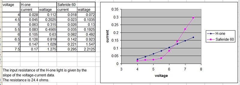
U H-One S Saferide 60
4.0V 28 mA 18 mA
4.5V 45 mA 23 mA
5.0V 63 mA 26 mA
5.5V 83 mA 35 mA
6.0V 105 mA 82 mA
6.5V 126 mA 142 mA
7.0V 147 mA 221 mA
7.5V 170 mA 295 mA
 
Last edited:

Steve K

Flashlight Enthusiast
Joined
Jun 10, 2002
Messages
2,786
Location
Peoria, IL
thanks for the data!
I've put it into a spreadsheet to see what it can tell me....

12134966744_18dd64a455_c_d.jpg


The H-one has a very resistive behavior, with a resistance of roughly 24 ohms. I'm curious as to how they've achieved this. Probably just stuck a resistor in series with the LED, but I'd have to run the numbers to see if the resistance seen by the dynamo would be this linear, especially down near the white LED's Vf.

By comparison, the Saferide has a voltage-current curve that looks a lot like a diode. I think this is using a 50% duty cycle buck converter to double the LED's impedance as seen by the dynamo.
edit: sorry... I just recalled Sam's comment about the Saferide using two LEDs, which are probably wired in series. Well, I think that Philips avoided using any electronics other than a bridge rectifier, since this certainly has the characteristics of two LEDs wired in series. (end of edit)

So what does this tell us? Well, it tells me that if I wanted to use multiple H-one lights with a dynamo, I'd want to wire them in parallel. If I wanted to use multiple Saferide 60's, I'd wire them in series. It also tells me that the H-one is really not a great light! It would appear that it is wasting about half of the input power, and it's not even drawing very much power! Why wasn't it designed to draw 0.5A from the dynamo???

Anyway, that was a fun and somewhat enlightening exercise! Any other data on lights available??
 
Last edited:

swhs

Newly Enlightened
Joined
Oct 10, 2007
Messages
113
Location
Netherlands
thanks for the data!
I've put it into a spreadsheet to see what it can tell me....

12134966744_18dd64a455_c_d.jpg


The H-one has a very resistive behavior, with a resistance of roughly 24 ohms. I'm curious as to how they've achieved this. Probably just stuck a resistor in series with the LED, but I'd have to run the numbers to see if the resistance seen by the dynamo would be this linear, especially down near the white LED's Vf.

By comparison, the Saferide has a voltage-current curve that looks a lot like a diode. I think this is using a 50% duty cycle buck converter to double the LED's impedance as seen by the dynamo.
edit: sorry... I just recalled Sam's comment about the Saferide using two LEDs, which are probably wired in series. Well, I think that Philips avoided using any electronics other than a bridge rectifier, since this certainly has the characteristics of two LEDs wired in series. (end of edit)

That's obviously not the case... See my site :

http://swhs.home.xs4all.nl/fiets/te...ips_saferide_led_dynamo/analyse/index_en.html

So what does this tell us? Well, it tells me that if I wanted to use multiple H-one lights with a dynamo, I'd want to wire them in parallel. If I wanted to use multiple Saferide 60's, I'd wire them in series. It also tells me that the H-one is really not a great light! It would appear that it is wasting about half of the input power, and it's not even drawing very much power! Why wasn't it designed to draw 0.5A from the dynamo???

But they do... The fact is that what I asked before, whether you were curious about DC or AC measurements, matters a lot because these headlamps are not resistive loads. They all try to get about 2.4W at the LEDs at 15 km/h (which is where the dynamo should give 6Veff at 0.5A) as StVZO mandates the power to the main light source to be in the range of 2.4 *0.8 to 2.4 *1.1. So the H-one S certainly does not waste power, in fact without a taillamp it puts out more power to the main LED than allowed by StVZO. See for more on power requirements:

http://swhs.home.xs4all.nl/fiets/tests/verlichting/verkeersregels/de_stvzo/index_en.html

The only thing my measurements show is how much power draw there is on a DC source which can be of use to know what the best way is to use one or more headlamps on a battery. For efficiency, measurement at the LEDs would be needed. And for actual performance on a dynamo, it needs to be measured on AC...
 

Steve K

Flashlight Enthusiast
Joined
Jun 10, 2002
Messages
2,786
Location
Peoria, IL
Well, I wasn't considering that the lights might use a large series cap to match the light's impedance to the dynamo at a range of frequencies. The fact that DC power was able to power the lights shows that this wasn't being used. Maybe they had a series cap with a resistance in parallel? That might explain the H-one?

The Saferide might be a mystery, though... There is a switching power supply on the bottom, along with a really large electrolytic cap and a supercap. The photos don't show how the electrolytic cap is wired to the board, so I can't tell if it is intended to be a series cap, or if it is just the output cap for the switcher. It is rated for 25v, which is excessive for the switcher, so perhaps it is a series cap.
Wait.... I can see the leads coming through the board in this photo...
http://swhs.home.xs4all.nl/fiets/te...hilips_saferide_led_dynamo/analyse/open-9.jpg
The leads are just to the right of the big TVS diode, which is to the right of the bridge rectifier. It's hard to be sure, but it is very possible that it is wired in series with the power from the dynamo. Weird.... there must be something else going on too, or you wouldn't have been able to power it from DC. The mystery just gets deeper! :)

Another thought about using a series capacitor... it is used to compensate for the dynamo inductance. I wonder what happens when used with a large hub dynamo compared to a small bottle dynamo? The characteristics of the two should be different, judging just by the physical size of the windings.

I'm not sure what the switcher is for, though. Just for the standlight, perhaps?
I do appreciate the teardown of the Saferide light. It provides quite a bit of info that is just not available by measuring the characteristics at the terminals.
 
Top