Solar panel battery charger circuit

YoSuk

Newly Enlightened
Joined
Mar 7, 2014
Messages
6
Hello, first time posting here! :p

We are currently working on a project involving electronic equipment which have to be unattended to for long periods of time and powered by LI-Ion batteries. We plan to augment the battery life using a small solar panel. The plan is to use 4 LI-Ion batteries in parallel, which will be charged by a bq24650 IC chip connected to the solar panel. In the sample schematics provided in the datasheet, the bcq24650 is powered by the solar panel. However, our panel is only able to deliver 3.85V as a maximum voltage rating. We therefore plan to power the bq24650 from a LT1111 step-up voltage regulator connected to the batteries, which will provide the 5V needed.

The question is, is this a good solution? The goal is to make the batteries last as long as possible with limited space and without the possibility to recharge the batteries manually. Due to the limited space we cant use a bigger panel, so eventually the batteries will run out. Our circuit would look something like this, but with different values for the resistors/capacitors:

charger_circuit_ver_1.png


Is this the right way to place the load on the battery? Or do we need some sort of protection between the battery and load? Is it okay to charge the batteries in a paralell configuration like this?

Here is a list of all the components of the charger and battery circuit:


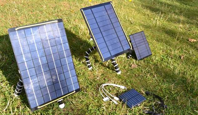
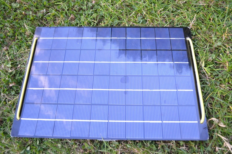
Solar panel: http://no.farnell.com/multicomp/mc-sp0-8-nf-gcs/solar-panel-0-8w-4v-no-frame/dp/1852494

Battery manager IC-chip: http://www.ti.com/lit/ds/symlink/bq24650.pdf

Step-up power regulator: http://cds.linear.com/docs/en/datasheet/1111fd.pdf

LI-Ion batteries: http://powers.media.mit.edu/wiki/upload/ANR26650M1_Datasheet_MARCH_2008.pdf


Any information would be greatly appreciated! :thumbsup:

- Yosuk
 

hiuintahs

Flashlight Enthusiast
Joined
Sep 12, 2006
Messages
1,840
Location
Utah
1st of all I think you are OK with the LI-Ion cells in parallel. Once they are all installed and equalized, then they will all be the same voltage.

I think I'd prototype a couple of different methods. As far as whether you need some type of MPP type of charger, it depends on how much power your load is taking and if the batteries can stay charged with minimum amount of sun..........and thus MPP may not matter.


With the BQ24650 route, it has to have a minimum of 5v but you'd want to be a little higher just so that you aren't sitting on the minimum. Since you would need a boost converter to bump the voltage up to the BQ24650 minimum, why not just utilize the boost converter as the charging mechanism and skip the BQ24650 altogether. What you would do is integrate into the FB pin both constant current and the 4.20v max voltage limit in a "diode-or'ed" fashion using a couple of op-amps so as to not get the diode drop and to get precision. You'd set the output voltage to 4.20 volts and I think I'd set the current to something under 230mA, like 150mA or even 100mA. Then if wanting to take it to the next level of complexity would be to allow the current limit to vary as the power of the panel changes.

The tricky part is that the input voltage (solar) and the output voltage are right around the same value. For boost you need to have some input voltage margin below the desired output. If this idea interests you take a look at On-Semiconductor's NCP1421. I've used this part and you can get as close as a couple of tenths of volt between input to output before the output just rises with input.

Thus you'd have to put a series P-channel mosfet between charger and batteries that opens up at 4.20v so that the batteries never get overcharged. That FET would be controlled by a comparator with some hysteresis.

Anyhow just some thoughts. Sounds like an interesting project.
 
Last edited:

SemiMan

Banned
Joined
Jan 13, 2005
Messages
3,899
The boost converter will collapse the output voltage of the solar panel and essentially you will get nothing out. Boost will keep drawing more input current to get the output up... Which causes the panel voltage to drop further reducing the input power. It may work if turned on under full sun but will not restart as the sun goes down and comes up.
 

Steve K

Flashlight Enthusiast
Joined
Jun 10, 2002
Messages
2,786
Location
Peoria, IL
Offhand, my impression is that you need to sit down and learn about solar panels, battery charging, and switching power supplies.

My first thoughts:
1. have you done calculations to determine how much power your load will draw and sized the solar panel and battery pack accordingly?
2. Once you've determined the amount of power needed from the solar panel, have you accounted for the issues of cloudy skies, changes in sun elevation, obstruction by nearby objects, etc.? Have you accounted for the change in the solar panel's characteristics due to temperature?
3. Have you looked for a panel with the same power rating, but a higher open circuit voltage and smaller short circuit current? The cells in the panel you've chosen could be rewired to achieve this. That would allow the panel to meet input voltage requirement for the T.I. buck converter and charge controller.
4. what voltage range can the load operate with? i.e. does the load need 3.3v +/- 5%, or can it operate over the whole range of the battery voltage?
5. what protection is there to avoid excessive discharging of the batteries?

Generally, since you don't seem to have a good hand on the details of this issue, I'd recommend changing the design to something simple and robust. Change the battery to nicad.. use three cells in series to get roughly the same battery terminal voltage. Wire a schottky diode between the solar panel and the nicad battery, and stop there. The panel can now directly charge the battery with no losses in a buck converter. The nicads can tolerate continued trickle charging, especially if you keep the same capacity as the lithium battery. Even with a smaller capacity, nicads can tolerate trickling at C/10. You might want to add a circuit to avoid over discharge of the battery, though.
 

SemiMan

Banned
Joined
Jan 13, 2005
Messages
3,899
A higher voltage input panel would be by far the easiest solution.

Semiman
 

YoSuk

Newly Enlightened
Joined
Mar 7, 2014
Messages
6
Thank you all for your replies! Sorry for the late response, but i have been reading up on battery charging and management. :)

I have reconfigured my circuit and dropped the bq25650 for a much simpler circuit:


Battery_circuit.png


This circuit, if i have understood the datasheet correctly, will keep a regulated output voltage of around 3.6V, which is the voltage required to charge the LiFePO4 battery used in the application.

What i now need is a circuit to prevent overcharging and prevent undervoltage. The battery datasheet lists the "discharge cutoff" as 1.8V. Is this the lowest recommended voltage the battery can reach without damaging it? The solar panel in the project can not be changed for one with a higher voltage/power output, and the batteries has to be LiFePO4 type batteries. The entire purpose of the solar panel is to help extend the battery life of the batteries. The load in question will on average use around 1mA of current, with a maximum of 500mA for short periods.

I have been searching for battery management ICs, but have been unable to find any that provides overcharging and undervoltage protection for LiFePO4 type batteries. Does anyone have any suggestions as to how i can protect the batteries from overcharing and under voltage?
 
Last edited:

sirpetr

Newly Enlightened
Joined
Sep 7, 2012
Messages
96
Location
Czech Republic, Prague
LTC3105 looks like good choice for solar powered charger. For undervoltage or overvoltage you can use MCU to monitor voltage with ADC and when it finds the voltage is outside working range, it shuts off N-mos. Or you can choose this whole analog circuit.
 

hiuintahs

Flashlight Enthusiast
Joined
Sep 12, 2006
Messages
1,840
Location
Utah
At first I was going to suggest you build up your own charging circuit but that LTC3105 looks promising. You shouldn't have to worry about an overcharging circuit because the LTC3105 allows you to set whatever max voltage you want. When the battery is below that max, it will just draw more current into the battery and when it's close to your fully charged value, there simply won't be much current pumped into the battery. In other words the LTC3105 will keep the battery from going over that programmed FB value. For LiFePO4, I'm wondering if something lower than 3.6v would be better since its going to be utilized more as a trickle charger rather than a wam, bam charge it up fast setup.

As far as an under-voltage circuit goes, I would just use a P-channel mosfet in series with your load and controlled by a voltage comparator set to whatever value is deemed good for your battery (2.1v?). You'd have to have some hysteresis on it such that it wouldn't oscillate on/off when near the trip point. If more decision making has to take place I'd use a microcontroller that will give you much more control and reprogram ability to allow you to suit your needs as you discover them.

I've used Microchips PIC10LF322 in a system that was powered by just 2 AAA batteries. It's VDD range is 1.8v to 3.6v with absolute maximum of 4.0v so well within your power source. It's a little SOT23-6 part but you only need to read the battery voltage on one pin and another pin configured as a digital output to control the mosfet.......and the PIC10LF322 draws very low power.......especially if it is put to sleep when not needed.

Just some thoughts :).
 
Last edited:

toysareforboys

Enlightened
Joined
Feb 23, 2009
Messages
249
Location
Whitby, Ontario, Canada
What are you powering from the batteries? I have a very similar setup to yours and here's how I did it:

4 x Panasonic NCR18650B 3400mah unprotected batteries Fasttech SKU# 1141100 ($15 x 4)
1 x Quad battery box, 5v USB 2amp changing input, 5v USB 2amp output. Ebay item # 281051309794 ($20) (basically this is a cheap 4 x 18650 2 amp battery charger and 5v power supply for RaspberryPi)
1 x Quad Panel 1.5 amp 5V solar panel folder built by cottonpickers: http://www.cpfmarketplace.com/mp/sh...Solar-Powered-amp-USB-Chargers-2-panels-added ($199)

The quad panel is quite a bit overkill for my purpose (6 amps at 5v output, can be wired for 10v at 3 amps or 20v at 1.5 amps). All of the above runs a RaspberryPi 24/7

He also sells a single panel that does 1.5 amps at 5v, it's really nice ($74):

g9bf.png


k75p.jpg


It has a 1/4" tripod socket on the back, standard USB port output (5v at 1.5 amps) works great with Gorillapod's, etc.

Hopefully that gives you some ideas :)

EDIT: Wow, those are pretty strange 26550 batteries you plan on using! lol. I can't believe how flat the output voltage curve is! Here's spec sheet on the NCR18650B's in case your interested, and the normal 26650's I use are these 4500mah ones.

-Jamie M.
 
Last edited:

YoSuk

Newly Enlightened
Joined
Mar 7, 2014
Messages
6
sirpetr:
Thanks for the tip :) I will try to avoid using more MCUs though, as it will really be a hassle to program different MCUs with different flashers and developers programs :)

hiuintahs:
Hmmm, i thought the battery had to be "disconnected" from the charging circuit once it was fully charged? Won't it damage the battery if i keep trying to charge it once its full? The charging current will be quite low though, with the solar panel delivering a maximum of 0.8W. As for lower charging voltage, won't that affect the lifetime of the battery? I thought all Li batteries had to be charged at a +-50mV of the charging voltage? If that is not the case, what voltage should i use then? :)

This is the current circuit with an undervoltage protection circuit added:

New_charging_circuit.png

I figured it might as well cut the voltage at around 2.5V since the load requires a voltage of between 2.7V and 3.6V. :)


toysareforboys:
I am powering a small radio node which will transmit various sensor data :) Hehe, the tiny panel on the ground looks pretty much like the one i plan on using.


- Ole
 
Last edited:

hiuintahs

Flashlight Enthusiast
Joined
Sep 12, 2006
Messages
1,840
Location
Utah
hiuintahs:
Hmmm, i thought the battery had to be "disconnected" from the charging circuit once it was fully charged? Won't it damage the battery if i keep trying to charge it once its full? The charging current will be quite low though, with the solar panel delivering a maximum of 0.8W. As for lower charging voltage, won't that affect the lifetime of the battery? I thought all Li batteries had to be charged at a +-50mV of the charging voltage? If that is not the case, what voltage should i use then? :)
The charging circuit (LTC3105) won't keep charging the battery once the set point voltage is reached. But it will keep it at that voltage. So the question is: can the LiFePO4 handle being at 3.6v for long periods of time?

I have to admit I am not as familiar with LiFePO4 as I am with 4.2v lithium ion. What little I have read up on the LiFePO4 batteries is that 3.6v is maximum charge it up voltage but it isn't a voltage that is kept on the battery but only reached during charge.......which I thought that was when you charged it up fairly rapidly.

I guess what I was thinking was to utilize the LTC3105 as a trickle charger set at 3.4v (whatever voltage is safe to keep the LiFePO4 without degradation) since your solar system isn't that powerful. And that way the battery wouldn't have to be disconnected from the LTC3105.

If not then you'd set the LTC3105 to 3.6v with a comparator controlling a mosfet to turn on at say 3.3v and off when it hits 3.6v. I have an Excel spreadsheet that calculates the value of resistors for hysterisis by the way if going the analog way.

When I get some time I'll look over your comparator circuit. I noticed that you are picking a lot of Linear Technology parts. I like LT parts but they are kind of expensive and I favor others when the opportunity arises.

"I thought all Li batteries had to be charged at a +-50mV of the charging voltage? If that is not the case, what voltage should i use then?"

Not sure what you mean by that.
 

YoSuk

Newly Enlightened
Joined
Mar 7, 2014
Messages
6
Hi,
Thank you for your help and sorry for the late reply, i haven't had a lot of spare time recently :) The question then is whenever the batteries will be damaged if i keep a constant voltage of 3.4V for long periods of time. The solar panel have a maximum current of 0.2A in bright sunlight, so normally i would guess the charging current would only be around 0.1A at best. Will the batteries be damaged if they are kept at 3.4V? Or is it better to lower the voltage to 3.3 or somewhere close to that voltage?

What i ment by "+-50mV of the charging voltage" is that i have read somewhere that the batteries have to be charged at +-50mV of the optimal charging voltage, meaning that for the LiFePO4 batteries, that would mean between 3.55V and 3.65V. I dont know if this really is the case though :)

Thanks you again for your help :)

-Ole
 

hiuintahs

Flashlight Enthusiast
Joined
Sep 12, 2006
Messages
1,840
Location
Utah
.........What i meant by "+-50mV of the charging voltage" is that i have read somewhere that the batteries have to be charged at +-50mV of the optimal charging voltage, meaning that for the LiFePO4 batteries, that would mean between 3.55V and 3.65V. I dont know if this really is the case though :)

Thanks you again for your help :)

-Ole

I think there is some confusion with the 3.60v value. 3.60v is the fully charged state of the battery. When the battery is discharged, its voltage will be quite a bit lower than this and you can't just put 3.60v +/-.05v back onto the battery with a charger to bring it up in charge. It doesn't work this way.

To force charge back into the battery, a voltage above what it is currently sitting at is needed to overcome the internal resistance of the battery. And that value will be just a little above the actual battery voltage. Otherwise the charge current is very high.

I have found with regular lithium ion that when charging it with a full 1 amp of current, the charger has to raise its voltage to about 0.1v above the battery voltage to force that much current into the battery. If the charge rate is half that then even a less delta voltage is required.

Thus commercial chargers manage the charge process by holding a constant current charge and they do this by putting whatever voltage above the battery is needed to maintain that constant current...........until maximum voltage is reached, then they prevent the voltage from going any higher which means that the charge current is now going to decay as the battery continues to take on further charge but its voltage is kept from rising. Termination is determined to be when the original charge current decays to a certain percentage of its original charging level.

For your LiFePO4 battery, 3.60v is maximum voltage and the resting voltage of a fully charged battery. Since I don't think your solar panel can output too high of a current to damage the battery, you just set up your electronics as a trickle type of charger with a maximum output voltage of 3.60v. That is done by 2 resistors connected to the FB pin of the LTC3105. Any time your battery drops below 3.60v and the sun is out, current will flow. Depending on how low the battery gets, means that even higher level of current will flow into it. But you wouldn't have to limit this current if the solar panels maximum current is below the maximum for the LiFePO4.

You also need to make sure that your electronics can never drain your battery below the minimum voltage that is acceptable for LiFePO4.
 

HKJ

Flashaholic
Joined
Mar 26, 2008
Messages
9,715
Location
Copenhagen, Denmark
For your LiFePO4 battery, 3.60v is maximum voltage and the resting voltage of a fully charged battery.

I have not seen a LiFePO4 with a 3.6 volt resting voltage yet, it is more like 3.4 volt.
Here is a charge curve. Charge is turned off at the yellow line and as can be seen the voltage drops to around 3.4 volt.
UltraFire%20ICR123A%203.0V%20800mAh%20(Green)-Charge.png


Here is another one:
A123%2026650%202500mAh%20(Green)-Charge.png
 

Gloh

Newly Enlightened
Joined
Mar 21, 2014
Messages
34
I know this may be a bit off topic with what's been said, but I was thinking of making a solar charger for my batteries a while back.
My concept was to charge a 12V lead-acid battery using a 12V regulator (off eBay) and a solar panel (size I did not figure out). I would then use a car charger adapter to charge the Li-ion batteries when the 12V battery was complete.
I never really considered how well the 12V battery would charge the Li-ion but I know it could work given the right equipment and setup.
But anyway, food for thought.
 

ChrisGarrett

Flashlight Enthusiast
Joined
Feb 2, 2012
Messages
5,726
Location
Miami, Florida
I know this may be a bit off topic with what's been said, but I was thinking of making a solar charger for my batteries a while back.
My concept was to charge a 12V lead-acid battery using a 12V regulator (off eBay) and a solar panel (size I did not figure out). I would then use a car charger adapter to charge the Li-ion batteries when the 12V battery was complete.
I never really considered how well the 12V battery would charge the Li-ion but I know it could work given the right equipment and setup.
But anyway, food for thought.

SystemRear.jpg


ControllerMaha1amp.jpg


http://www.candlepowerforums.com/vb/showthread.php?342073-Portable-solar-charging-setup-I-just-built

It's not that hard to do. If you can go 'rigid panels,' you get a lot more watts per dollar, than the portable rollable/foldable panels, which are more fragile and way more money.

Those are 30w monocrystaline panels that are relatively light at 5.5# ea. and fairly compact at 22"x18"x1" ea.. Total weight is just about 11#, not including the case, chargers and mother battery--that stuff being another 11#.

Charge up the battery(ies) by day, bring battery(ies) inside at night and charge your stuff up, all while sipping a nice cold beer. Repeat and rise as necessary.

Chris
 

Gloh

Newly Enlightened
Joined
Mar 21, 2014
Messages
34
SystemRear.jpg


ControllerMaha1amp.jpg


http://www.candlepowerforums.com/vb/showthread.php?342073-Portable-solar-charging-setup-I-just-built

It's not that hard to do. If you can go 'rigid panels,' you get a lot more watts per dollar, than the portable rollable/foldable panels, which are more fragile and way more money.

Those are 30w monocrystaline panels that are relatively light at 5.5# ea. and fairly compact at 22"x18"x1" ea.. Total weight is just about 11#, not including the case, chargers and mother battery--that stuff being another 11#.

Charge up the battery(ies) by day, bring battery(ies) inside at night and charge your stuff up, all while sipping a nice cold beer. Repeat and rise as necessary.

Chris

Sweet setup!
How long does it take to charge the LA battery and then the li ions?
Sounds like I have to try one of these soon!
 

ChrisGarrett

Flashlight Enthusiast
Joined
Feb 2, 2012
Messages
5,726
Location
Miami, Florida
Most SLA/AGM batteries are pretty much 100% at 12.8v-12.9v, after a couple of hours resting.

Going back 18 months, I think that I was able to charge up 8 Energizer 2300mAh cells, at 1A, which were let's say 50% full?

I don't think that I made a dent in the SLA/AGM at that point. It's 12Ah, so we don't want to go much below 50%-75% state of charge on those, although it's a deep cycle battery. If you're draining down to 25%, you might need more than a couple of hours to get it back up to 100%.

Maybe in Miami sun, it might take an hour, or two? My two panels in a laboratory, deliver 3.5A, then we have the digital controller's inefficiency of maybe 15%-20%, since it's PWM and not MPPT and finally, the NiMH/li-ion charger's inefficiencies, so things aren't 100% IN, 100% OUT.

I have a lot of options and most of my chargers will work in a car.

Chris
 

hiuintahs

Flashlight Enthusiast
Joined
Sep 12, 2006
Messages
1,840
Location
Utah
I have not seen a LiFePO4 with a 3.6 volt resting voltage yet, it is more like 3.4 volt.
Here is a charge curve. Charge is turned off at the yellow line and as can be seen the voltage drops to around 3.4 volt.

HKJ thanks for clarifying that. I'm not that familiar with LiFePO4. I had read that there was a push up to 3.6v in the charge process but wasn't sure that would be a good voltage at which a trickle charger should be set to which is why I mentioned in post #8:

"For LiFePO4, I'm wondering if something lower than 3.6v would be better since its going to be utilized more as a trickle charger rather........"

In post #14 I would just substitute 3.60 volts with 3.40 volts. Mostly in that post I was trying to point out ohms law in charging.

If it takes a final push up to 3.60 volts to get a full charge then the LiFePO4 would never get fully charged with the LTC3105 part. But that may not matter too much either. It would just would mean that the system would be using less of its capable battery capacity but how much lower I do not know. I know that if this was my project, I'd charge a LiFePO4 up to 3.40 volts and then discharge it to see exactly what the capacity was compared against what it should be.:)
 
Top