
HKJ
Flashaholic
[size=+3]Anti-reverse Driver Board AX2002[/size]


Driver is from banggood.com
[size=+2]Measurements[/size]
Single mode buck driver
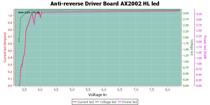
Tested with Cree XP-G2 led
Diameter: 17mm
Thickness: 6mm
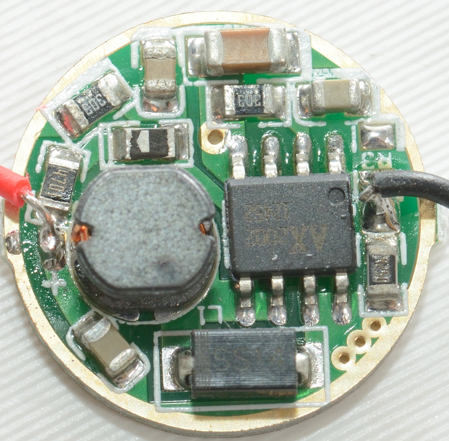
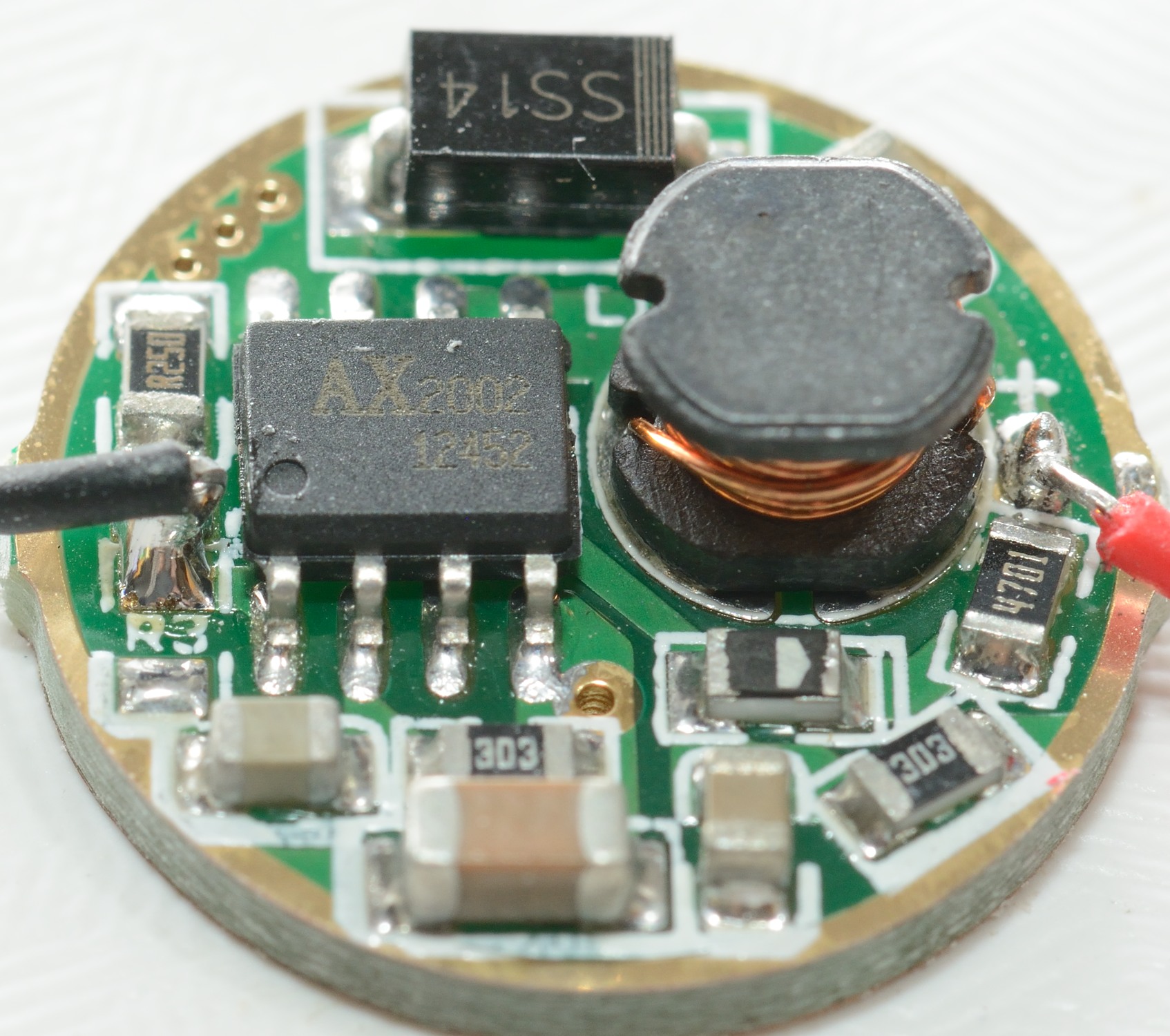
This driver is a buck chip (AX2002) with surrounding components, there is no microprocessor or other stuff on the board. This makes it very easy to change led current, in the datasheet for the AX2002 chip there is a resistance table with values from 20mA and up to 1.5A led current. On the board the resistor is just beside the black wire.
[size=+1]High[/size]

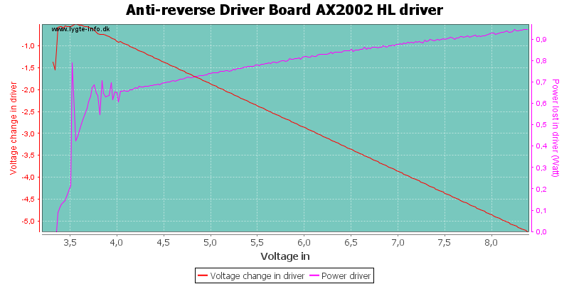
The driver has stable output from about 4 volt and up with around 80% efficiency.
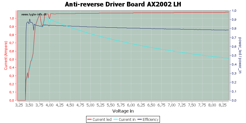
The driver starts at around 3.4 volt and because there is no low voltage warnings or anything it works exactly the same with increasing voltage as with decreasing voltage.
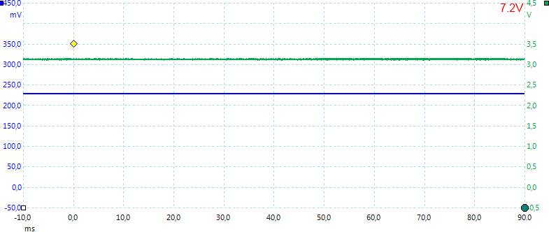
There is no noise in the output.
[size=+2]Conclusion[/size]
This is a simple driver for people that do not want modes, but just light.
[size=+2]Notes[/size]
How do I test a led driver
List of all tested drivers

Driver is from banggood.com
- Product name: Anti-reverse Driver Board AX2002
- Material: Double gold plated board
- current output: 1A
- current import: 3.3-8.4v
- Circuit board size: diamter 17mm x height 4.8mm
- PCB thickness: 1.5mm
- Protection:Reverse polarity protection, low voltage protection, mode memory function
- Suitable for the LED of type voltage 2.8-4V
[size=+2]Measurements[/size]
Single mode buck driver
Tested with Cree XP-G2 led
Diameter: 17mm
Thickness: 6mm
This driver is a buck chip (AX2002) with surrounding components, there is no microprocessor or other stuff on the board. This makes it very easy to change led current, in the datasheet for the AX2002 chip there is a resistance table with values from 20mA and up to 1.5A led current. On the board the resistor is just beside the black wire.
[size=+1]High[/size]
The driver has stable output from about 4 volt and up with around 80% efficiency.
The driver starts at around 3.4 volt and because there is no low voltage warnings or anything it works exactly the same with increasing voltage as with decreasing voltage.
There is no noise in the output.
[size=+2]Conclusion[/size]
This is a simple driver for people that do not want modes, but just light.
[size=+2]Notes[/size]
How do I test a led driver
List of all tested drivers