I've tried reading a few different posts on here to get an idea how this works but I'm still confused as to the details. I'm more interested in incans but I do like my LED's as well. So mainly I'm talking about my vinh made p60 drop in with a 2.8-4.5v driver which runs on a single li-ion. If I'm correct I believe he uses a 7135 driver and stacks them to get the required current. Now what I understand is the driver limits the voltage going to the LED to the proper vf and limits the current flow to what it's set at. In my case 3.5A for a neutral xm-l. Now if say the vf of that emitter is 3.6 volts the extra voltage from a fresh cell is burned off as heat and when the voltage of the cell is the same as the vf of the LED it's very efficient. So what happens when the battery drops below the vf. I can't tell any drop off in output until it hits the low voltage part of the design and drops to medium mode. Does the driver basically draw extra current and use it to up the voltage. They're called linear drivers but that seems to me it's boosting the voltage as well. So in a way it's a boost/buck driver. That's how I see it works anyway. Am I on the right track here?
You are using an out of date browser. It may not display this or other websites correctly.
You should upgrade or use an alternative browser.
You should upgrade or use an alternative browser.
How single cell led drivers work
- Thread starter vicv
- Start date

Curious_character
Flashlight Enthusiast
- Joined
- Nov 10, 2006
- Messages
- 1,211
I recall a long time ago when I was first studying electronics, having difficulty understanding current sources. We're used to dealing with more-or-less constant voltage sources like mains power and batteries (although regarding batteries as having constant voltage can lead us astray, too). But you've got to get around the idea of a constant current source to understand LED drivers.
An LED is very different from a resistor and even more different from an incandescent bulb. I have in front of me a data sheet for a Luminus SST-50 power LED so I'll use it as an example. All LEDs act very much the same way, just at different power levels.
At 3 volts forward, this LED draws about 1 amp. At 3.25 volts it draws about 2 amps. At 3.5 volts it draws about 4.5 amps. So for every quarter volt of forward voltage the current doesn't change by some fixed amount like a resistor would -- it doubles! Furthermore, if you were to fix the voltage, the current and power dissipation would increase about 10% for every 10 degree C temperature increase. It would get hotter, draw more current which would make it get hotter, and so forth until it either hits a supply limit or self destructs. This is known as "thermal runaway". A "direct drive" system works only because of internal battery resistance, not something you can count on if you really care how hard you'll be driving the LED.
So it's a very bad idea to try to run an LED with a constant voltage like you do an incandescent lamp. That's where constant current "sources" (usually made of a more-or-less constant voltage source and a special regulator) come in. A constant current driver will provide a constant current to the LED, letting the LED voltage be whatever it needs to be. Looking at the same thermal characteristic when driven with a constant current, if the temperature increases 10 degrees C, the voltage will decrease about 25 mV. This will make the LED dissipation actually decrease, but by only about 25/3250 or less than 1%.
In order for a constant current regulator to work, it has to provide enough voltage for the LED to consume the desired current. For example, for the SST-50, you'd need it to be able to provide at least 3.25 volts if you want to run the LED at 2 amps. If the driver could provide only 3 volts, the LED would consume only about 1 amp -- at room temperature, that is. It would vary considerably with temperature.
There are two basic classes of regulators, passive (or linear) and active (or switching). The 7135 is a passive regulator. Your idea of how it works is generally correct, but don't think of it as limiting the voltage. What it does is limit the current to a fixed value. The output voltage is whatever the LED voltage is at that current. Like any passive regulator, the output voltage must be less than the input voltage. The greater the difference, the more power the regulator dissipates as heat (V * I) where V = voltage drop across the regulator and I = the current through it, so the less efficient it is. When the input-to-output drop gets too low for the circuitry (that is, the battery voltage isn't enough greater than the required LED voltage), the current drops below the regulated value and the 7135 acts pretty much like a low value resistor. As the supply voltage and LED voltage drop, the LED current drops dramatically -- halving each time the voltage drops a quarter of a volt. The other type of regulator is an active one which can transform the supply voltage to a higher or lower value in order to furnish the LED with whatever voltage it needs to draw the desired current. Boost regulators produce a higher output voltage than the supply, and buck regulators a lower voltage. Buck-boost can do either but are more complex and tend to be a bit less efficient. A well designed active (switching) regulator can typically achieve an efficiency of 80 - 90% over a wide range of input-output voltage differentials.
Hope this helps.
c_c
calipsoii
Flashlight Enthusiast
- Joined
- Apr 21, 2010
- Messages
- 1,412
The XM-L has a considerably lower Vf than most power LED's. The datasheet rates it at 2.7V @ 700ma and down to 2.63 @ 200ma. This is why your light continues to run even as your battery drops below 3.7V.
Most 7135-based drivers do not have boost capacity - the inductor and accompanying electronics won't fit on the boards along with all the 7135 chips. An inductor trying to boost 3.7V off a depleted cell would probably draw 4-5x the amperage you're targeting (2A would probably have 6A peaks) and would need to be huge as a result. There's no room on a 17mm MCPCB for that.
Most 7135-based drivers do not have boost capacity - the inductor and accompanying electronics won't fit on the boards along with all the 7135 chips. An inductor trying to boost 3.7V off a depleted cell would probably draw 4-5x the amperage you're targeting (2A would probably have 6A peaks) and would need to be huge as a result. There's no room on a 17mm MCPCB for that.
......... Now what I understand is the driver limits the voltage going to the LED to the proper vf and limits the current flow to what it's set at. In my case 3.5A for a neutral xm-l. Now if say the vf of that emitter is 3.6 volts the extra voltage from a fresh cell is burned off as heat and when the voltage of the cell is the same as the vf of the LED it's very efficient. So what happens when the battery drops below the vf?...........
What you said above is correct......and battery below Vf the light starts to dimm. Actually its Vf + the 7135's LDO value of 120mV.
There is no buck boost or switching type of action on the 7135 from what I've seen. (Someone straighten me out if I'm wrong). I did take a look at the data sheet and this is a linear low drop out regulator (LDO) type of device configured internally as a current source.
The spec sheet says it will operate from 2.7v up to 6v but that doesn't mean that the LED will be powered if the battery voltage gets that low. It all depends on what the Vf (forward voltage drop) of the LED is.
Without an inductor there is no buck-boost or switching type of action taking place.
The data sheet shows it hooked up with power going from the battery to the anode of the LED and then from the cathode of the LED to the "out" pin of the 7135 with the 7135 then connected to ground.
Since this is a current regulated device (I think nominally 360mA), then the 7135 will adjust its voltage at the "out" pin such that the Vf of the LED creates the constant current. (You pointed that out). It looks like you might be able to parallel several of these to increase the current through an LED.
Typical LDO is 120mv on the 7135. So your battery voltage can go as low as Vf + 120mV before it can't hold current regulation and the current starts to drop as the battery voltage continues to drop.
You are right, all excess battery power beyond the Vf will be dumped across the 7135. Thus the closer the battery voltage is to Vf+120mV the more efficient it is.
Excellent answers everyone thank you. That clears a lot up. I took a few electronics courses when going through trade school to become an electrician so I understand some basic electronics. I was under the impression though that the vf was the voltage when an led would turn on because it's a diode. And if the voltage was lower than that it just wouldn't turn on. Not be dimmer. And as soon as it started conducting it would basically draw infinite current until it blew so we'd put a resistor in series with it to limit the current. That's why I thought a regulator would lock in the voltage to the vf or slightly above and ad variable resistance like a potentiometer until set current was established. Turns out I was very wrong ") Oh well it happens sometimes. So if the vf isn't the voltage required for the LED to conduct current what is it? And an older led with a higher vf will drop out of regulation and continually dim once the battery voltage becomes lower than the vf? That would make sense how light like surefire that run on primaries get dimmer and dimmer as the battery depletes
Oh well it happens sometimes. So if the vf isn't the voltage required for the LED to conduct current what is it? And an older led with a higher vf will drop out of regulation and continually dim once the battery voltage becomes lower than the vf? That would make sense how light like surefire that run on primaries get dimmer and dimmer as the battery depletes
Oh well it happens sometimes. So if the vf isn't the voltage required for the LED to conduct current what is it? And an older led with a higher vf will drop out of regulation and continually dim once the battery voltage becomes lower than the vf? That would make sense how light like surefire that run on primaries get dimmer and dimmer as the battery depletes............ I was under the impression though that the vf was the voltage when an led would turn on because it's a diode. And if the voltage was lower than that it just wouldn't turn on. Not be dimmer. And as soon as it started conducting it would basically draw infinite current until it blew so we'd put a resistor in series with it to limit the current. That's why I thought a regulator would lock in the voltage to the vf or slightly above and ad variable resistance like a potentiometer until set current was established. Turns out I was very wrong........
No you are mostly right. The transition or small voltage change of Vf from totally blocking current to basically a diode that is full on is very narrow. It's hard for a person to just put the same voltage on an LED and expect similar results from LED to LED because of the tolerances from part to part differ and since that window is narrow.
But in a current feedback regulated system, it will adjust its output (in voltage) such that the Vf is at the right level to maintain its set current. So the Vf isn't at a fixed value in a driver system that has different outputs but varies but its not by much. That is why you either have a current regulated feedback system that can minutely adjust the Vf or you can do it like you mentioned with counting on a typical Vf and then dropping the rest of the power across a resistor to limit the current.
HKJ
Flashaholic
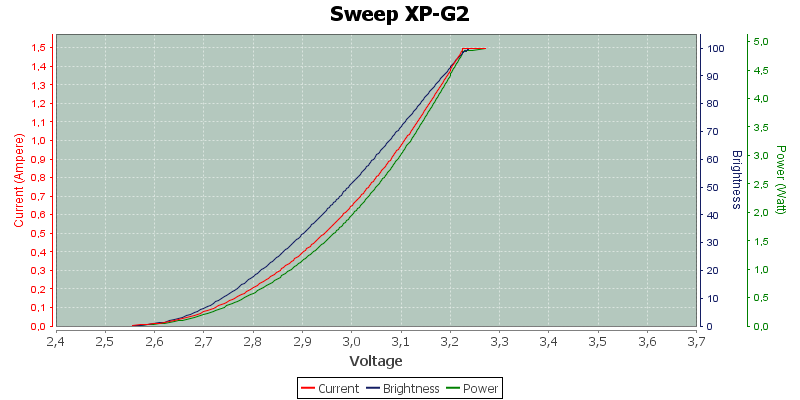
The transition from off to on is not that sharp, but the actual transition voltage will vary between leds. This makes constant current drivers the safest way to drive leds.
Here is the curve for a typical led:
Here is the curve for a typical led:
Ok. So for something like an xpe that has a vf of 3.6V once your cell drops below that underload the emitter goes out of regulation and diminishes until it hits that 2.9v cutoff? And I'm still not sure I'm understanding. I understand the voltage needed for the LED to conduct it narrow and anything over increases current a lot but when the battery depletes to a lower level than the vf I'm being told the LED will steadily diminish but if it's lower than the vf and the driver isn't boosting voltage how can the LED continue to conduct?
HKJ
Flashaholic
Ok. So for something like an xpe that has a vf of 3.6V once your cell drops below that underload the emitter goes out of regulation and diminishes until it hits that 2.9v cutoff? And I'm still not sure I'm understanding. I understand the voltage needed for the LED to conduct it narrow and anything over increases current a lot but when the battery depletes to a lower level than the vf I'm being told the LED will steadily diminish but if it's lower than the vf and the driver isn't boosting voltage how can the LED continue to conduct?
As you can see on the curve above the led will emit light down to about 2.6 volt.
Ok thanks. You must've posted that as I was posting my last reply. I always thought it was an abrupt turn on
I thought it was a bit tighter. That is what I get for not verifying the data sheet. Thanks for clarifying.The transition from off to on is not that sharp................
As the graph shows, a small change in voltage applied to an LED will produce a larger change in current. The operating voltage for a given current may be different for different LEDs from the same production line. Worse the current/voltage will change on a given LED with temperature, the LED drawing more current at a voltage as it heats up, making it easy for a voltage driven LED to experience thermal runaway.
Similar threads
- Replies
- 1
- Views
- 160