
The First Challenge here was to find a repeatable way to replace the negative contact inside of The Fulton.
I wanted to find a common part that anyone can find at their local hardware store that would allow them to upgrade their Fulton with either this mod, or The Ultimate Fulton regulated multi mode mod found HERE.
I actually toiled with this mod for many hours over the course of two days trying to find the right part and the best way to put this together.
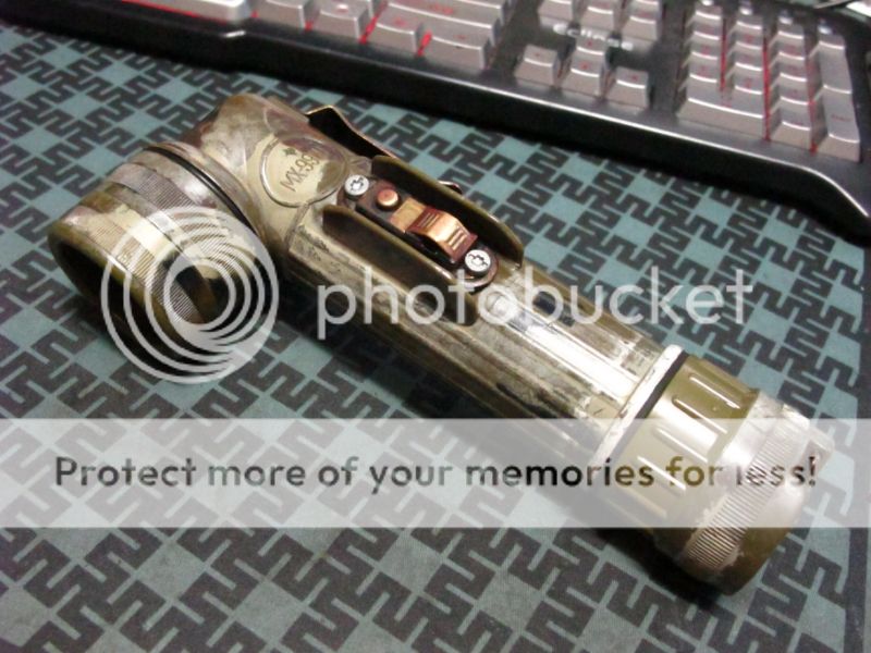
The Fultons biggest weakness is it's switch.
It was designed knowing it would only need to handle a very low wattage load.
The contacts on it tend to patina over time in such a way that will incur a higher level of resistance then we'd like.
This particular unit was quite suffering of that.
I bought this used on Ebay many years ago. It was in rough shape and I restored it as best I could but it would never shine as bright as it should.
Which brings us to the second motivation of this mod . . . to make it right.
I've been dabbling in the wonderful world of MOSFET's the past little while, and after discovering an almost endless supply of them in my scrap parts, I came to the realization that this was just the droid I was looking for to bring new life back to an old Fulton.
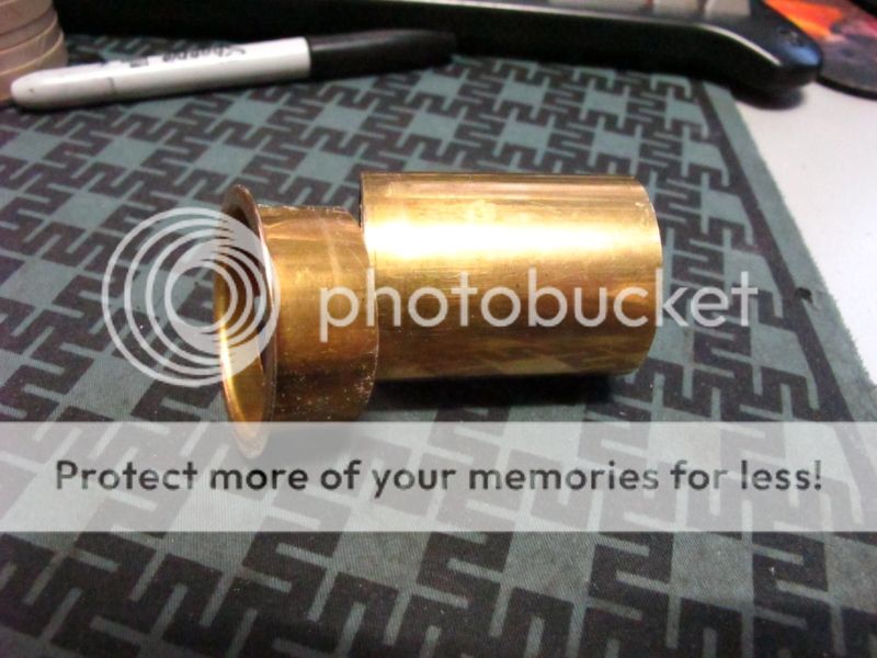
Found at a local hardware store this flange was a damn near perfect fit.
It's about 1.5" wide along the tube and comes in various several inch long lengths.
It sells for about $8 here in Canada which is somewhat disappointing as most of it will get cut off.
Fortunately, the Guy I dealt with at Home Hardware was willing to put the pipe cutter to it to save me some work.
The Flange gets cut down to 5/8" long.
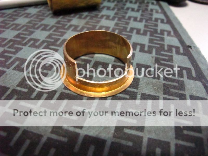
Seen here I dremeled a section away so that it would fit over the flat part on the bottom of the inside like so :
I would recommend making the cut as tight as you can to prevent rotation.
I didn't think of that until after.
At this point get to see how almost perfect it is.
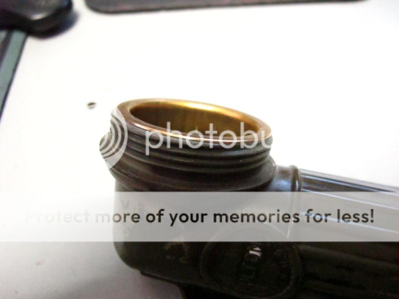
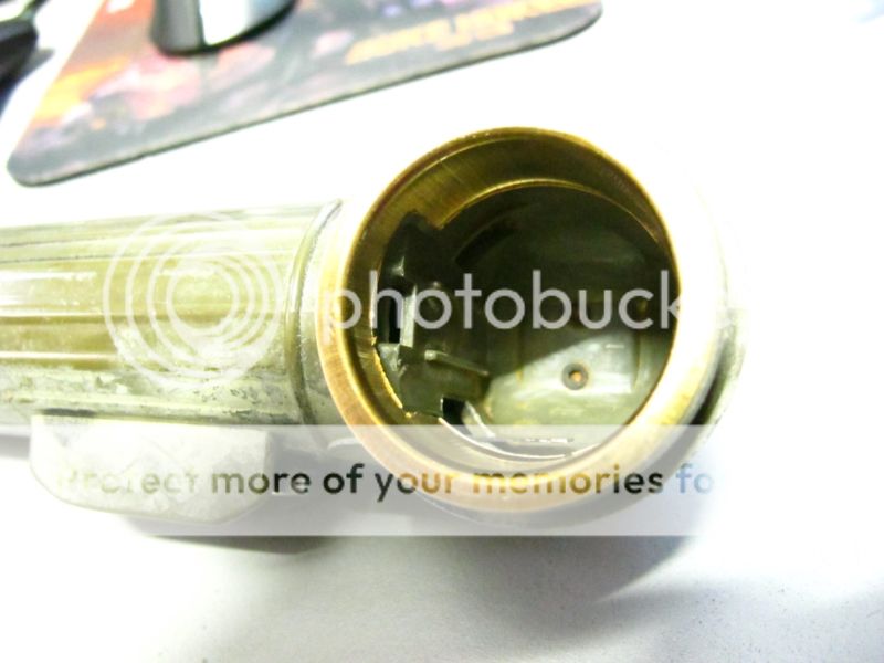
Now the catch is, due to the ID of the flange your reflector will no long sit flush, but as you can see, it's going to make a very good electrical contact.

The next catch is that the addition of this flange will no longer allow you to screw the bezel firmly down.
You're going to need to shave off the front until you find the correct depth you need to completely screw on the bezel.
This is easily done with a bit of spinny grindage on a piece of sandpaper on a flat surface.

The final catch to fitting this part is depending on the angle of your reflector and the bend in the flange, you may no longer be able to use the rear o-ring seal behind the reflector of you hope to make electrical contact.
If this is the case you can simply remove that seal and add an O-ring behind the bezel instead.
Just bare in mind your reflector will no longer be secure and will fall out when you remove the bezel.
Also be sure to take into account which setup you will be using when you sandpaper fit your Fulton.

In this next exercise I will integrate a MosFET into the Futons electrical to circumvent it's weaknesses.
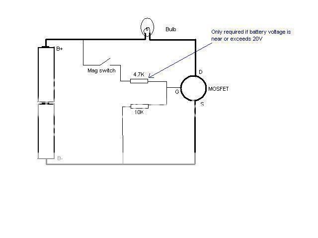
Seen here is the schematic I was working off of. I pulled it off another thread and I believe it was drawn by JimmyM.
The 4.7k resistor is omitted due to the low voltages I will be running.
I tried a couple different methods of mounting it in there but the part is very small and fragile and needs some form of protection or support. After damaging 2 Fets I finally settled on this method.
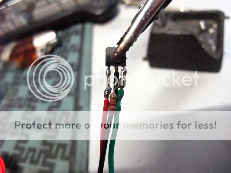
The FET used is an AOD472. It was salvaged off a computer motherboard which are an excellent source for power FET's.
It's rated for 20v 50a, and a Gate Threshold of 1.2-2.5v which I understand as the minimum working voltage it needs to fully close the circuit. These values make it perfect for a 2D sized application as it means I can still use this as a common 2D cell light.
I didn't have a 10k on hand. I've tested this circuit with various resistors from 1k to 22k and got the same results.
You need this resistor for the FET to work. It allows some Negative voltage to pass to tell the FET to turn OFF when no positive voltage is being applied to the gate. When positive is applied, it overpowers the negative coming off the resistor and tells the FET to turn ON. If no voltage it applied to the gate the FET will get confused by the load that is being applied across it and will allow some current to pass, at which point, it will function like a power resistor, heat up, and likely fry.
The value has to be high enough to prevent a short circuit from happening but low enough to allow enough current to pass to control the FET in off state.
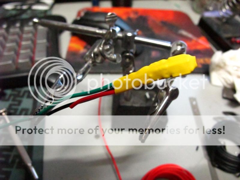
I packaged the FET in some heatshink. This will protect the FET and secure the wiring to take the strain off it's fragile little pins.
Green is (-in) from the Battery, Black is (-out) to the bulb, and Red is (+ Control) coming from the switch.
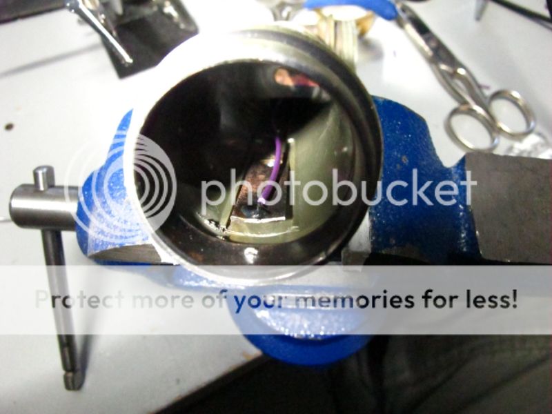
Cutting the switch link was meatball surgery. That purple wire is connected to the back of the (+) terminal that connects the batteries directly to the bulb.
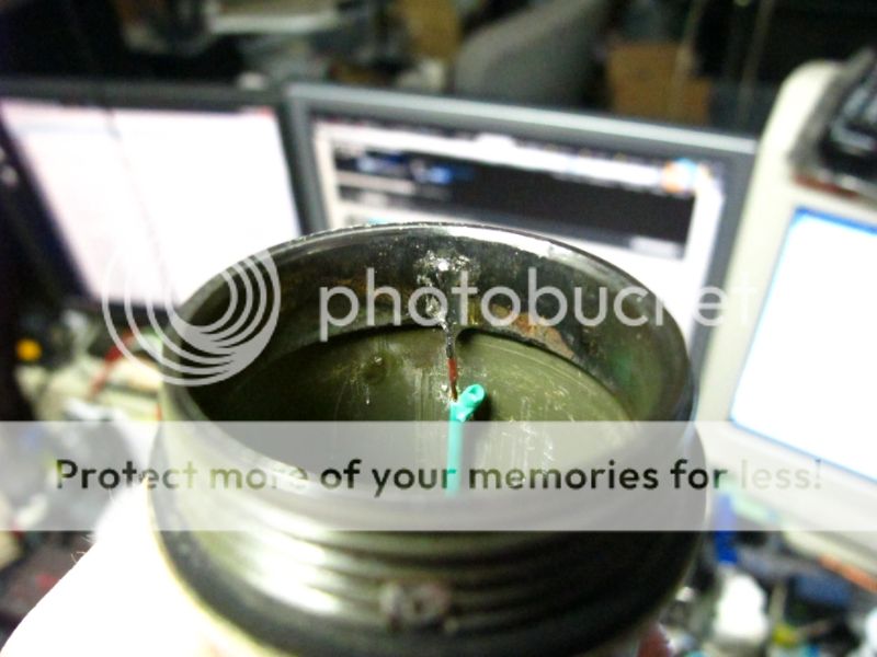
A quick and careful solder joint connects battery (-) to the FET.
And finally the trickiest part, packing it all in there and making the final connections.
18g solid copper wire was used. It makes for a good conductor but can be tricky to snake into small spaces.
You also have to be careful not to over work it or do any sharp bends. Once in place it won't be moving and should last a lifetime.
The Purple wire is 22g Stranded.
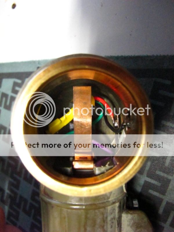
You can now visualize how the switch is connected.
Purple is soldered to the back of that terminal to send (+) to the switch which in return connects to the Red to control the FET.
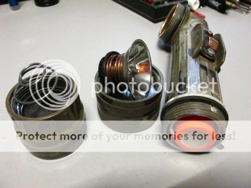
The Build is now complete.
A PVC tube adapts the light to take 2x26650 IMR or Lifepo4 cells. It will also secure and protect the new wiring in the tube.
26650's seem to fit perfect with no need to mod the tailcap.
D batteries still fit but snug.
The results are excellent.
The Fulton is now bright and responsive. No more flickering or fading with manipulation of the switch. The light is either ON or OFF. As long as the FET get's enough signal, it turns Full ON.
As you know, this also behaves as a resistance mod. This thing now rocks a ROP-Hi bulb to it's full potential. However, my testing has shown that a Fulton can only handle that amount or power for about 10 mins before overheating.
I have however thoroughly tested the Fulton with 10 watt ROP Low equiv for extended periods with no problems.
Running this light in my standard configuration: a Relfectalite 6v10w or (HPR71) off a pair of 26650 Lifepo4s has indeed shown an increase in output. The light burns whiter then it did before adding an edge over a brand new factory fresh Fulton.
The light is pulling 1.7a at the tail.
A stock Fulton has given me 1.6a.
Even an stock KPR bulb running off a pair of D cells seems whiter and brighter.
After this mod, I've come to the conclusion that a FET switch is a viable upgrade for any flashlight, as even the mild hotwire seems to be able to benefit from it. As I have an abundant supply of power FET's I can seem myself throwing them into all sorts of applications "jsut because". I may even be tempted to go and upgrade some of my old hotwires.
I wanted to find a common part that anyone can find at their local hardware store that would allow them to upgrade their Fulton with either this mod, or The Ultimate Fulton regulated multi mode mod found HERE.
I actually toiled with this mod for many hours over the course of two days trying to find the right part and the best way to put this together.
The Fultons biggest weakness is it's switch.
It was designed knowing it would only need to handle a very low wattage load.
The contacts on it tend to patina over time in such a way that will incur a higher level of resistance then we'd like.
This particular unit was quite suffering of that.
I bought this used on Ebay many years ago. It was in rough shape and I restored it as best I could but it would never shine as bright as it should.
Which brings us to the second motivation of this mod . . . to make it right.
I've been dabbling in the wonderful world of MOSFET's the past little while, and after discovering an almost endless supply of them in my scrap parts, I came to the realization that this was just the droid I was looking for to bring new life back to an old Fulton.
Found at a local hardware store this flange was a damn near perfect fit.
It's about 1.5" wide along the tube and comes in various several inch long lengths.
It sells for about $8 here in Canada which is somewhat disappointing as most of it will get cut off.
Fortunately, the Guy I dealt with at Home Hardware was willing to put the pipe cutter to it to save me some work.
The Flange gets cut down to 5/8" long.
Seen here I dremeled a section away so that it would fit over the flat part on the bottom of the inside like so :
I would recommend making the cut as tight as you can to prevent rotation.
I didn't think of that until after.
At this point get to see how almost perfect it is.
Now the catch is, due to the ID of the flange your reflector will no long sit flush, but as you can see, it's going to make a very good electrical contact.
The next catch is that the addition of this flange will no longer allow you to screw the bezel firmly down.
You're going to need to shave off the front until you find the correct depth you need to completely screw on the bezel.
This is easily done with a bit of spinny grindage on a piece of sandpaper on a flat surface.
The final catch to fitting this part is depending on the angle of your reflector and the bend in the flange, you may no longer be able to use the rear o-ring seal behind the reflector of you hope to make electrical contact.
If this is the case you can simply remove that seal and add an O-ring behind the bezel instead.
Just bare in mind your reflector will no longer be secure and will fall out when you remove the bezel.
Also be sure to take into account which setup you will be using when you sandpaper fit your Fulton.
In this next exercise I will integrate a MosFET into the Futons electrical to circumvent it's weaknesses.
Seen here is the schematic I was working off of. I pulled it off another thread and I believe it was drawn by JimmyM.
The 4.7k resistor is omitted due to the low voltages I will be running.
I tried a couple different methods of mounting it in there but the part is very small and fragile and needs some form of protection or support. After damaging 2 Fets I finally settled on this method.
The FET used is an AOD472. It was salvaged off a computer motherboard which are an excellent source for power FET's.
It's rated for 20v 50a, and a Gate Threshold of 1.2-2.5v which I understand as the minimum working voltage it needs to fully close the circuit. These values make it perfect for a 2D sized application as it means I can still use this as a common 2D cell light.
I didn't have a 10k on hand. I've tested this circuit with various resistors from 1k to 22k and got the same results.
You need this resistor for the FET to work. It allows some Negative voltage to pass to tell the FET to turn OFF when no positive voltage is being applied to the gate. When positive is applied, it overpowers the negative coming off the resistor and tells the FET to turn ON. If no voltage it applied to the gate the FET will get confused by the load that is being applied across it and will allow some current to pass, at which point, it will function like a power resistor, heat up, and likely fry.
The value has to be high enough to prevent a short circuit from happening but low enough to allow enough current to pass to control the FET in off state.
I packaged the FET in some heatshink. This will protect the FET and secure the wiring to take the strain off it's fragile little pins.
Green is (-in) from the Battery, Black is (-out) to the bulb, and Red is (+ Control) coming from the switch.
Cutting the switch link was meatball surgery. That purple wire is connected to the back of the (+) terminal that connects the batteries directly to the bulb.
A quick and careful solder joint connects battery (-) to the FET.
And finally the trickiest part, packing it all in there and making the final connections.
18g solid copper wire was used. It makes for a good conductor but can be tricky to snake into small spaces.
You also have to be careful not to over work it or do any sharp bends. Once in place it won't be moving and should last a lifetime.
The Purple wire is 22g Stranded.
You can now visualize how the switch is connected.
Purple is soldered to the back of that terminal to send (+) to the switch which in return connects to the Red to control the FET.
The Build is now complete.
A PVC tube adapts the light to take 2x26650 IMR or Lifepo4 cells. It will also secure and protect the new wiring in the tube.
26650's seem to fit perfect with no need to mod the tailcap.
D batteries still fit but snug.
The results are excellent.
The Fulton is now bright and responsive. No more flickering or fading with manipulation of the switch. The light is either ON or OFF. As long as the FET get's enough signal, it turns Full ON.
As you know, this also behaves as a resistance mod. This thing now rocks a ROP-Hi bulb to it's full potential. However, my testing has shown that a Fulton can only handle that amount or power for about 10 mins before overheating.
I have however thoroughly tested the Fulton with 10 watt ROP Low equiv for extended periods with no problems.
Running this light in my standard configuration: a Relfectalite 6v10w or (HPR71) off a pair of 26650 Lifepo4s has indeed shown an increase in output. The light burns whiter then it did before adding an edge over a brand new factory fresh Fulton.
The light is pulling 1.7a at the tail.
A stock Fulton has given me 1.6a.
Even an stock KPR bulb running off a pair of D cells seems whiter and brighter.
After this mod, I've come to the conclusion that a FET switch is a viable upgrade for any flashlight, as even the mild hotwire seems to be able to benefit from it. As I have an abundant supply of power FET's I can seem myself throwing them into all sorts of applications "jsut because". I may even be tempted to go and upgrade some of my old hotwires.
Last edited: