The IMR Enhanced Zener Mod to run the MT-G2

Conte

Enlightened
Joined
Dec 15, 2009
Messages
735
Location
Canada
IMG_0583_zps05aaf3c2.jpg


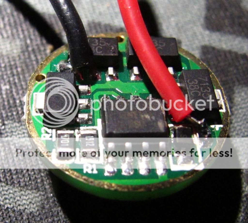
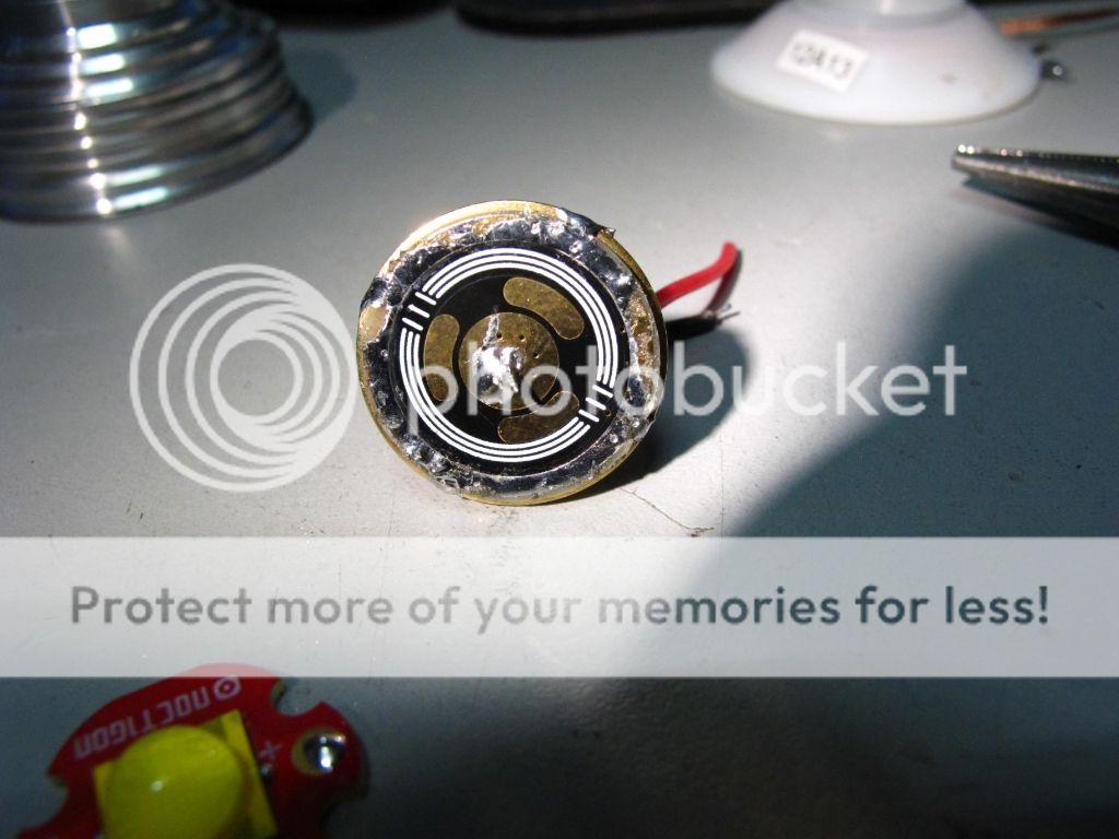
Seen here is a common 3A Qlite XML2 Driver.
Please make note of the 3 components across the bottom.
R2 and R1 on the Left, and D1 (unlabeled) on the Right under the red wire.

D1 is a diode that protects the MCU processor from reverse voltage.
R1 and 2 make up the voltage divider that delegate the low voltage cutoff.
As seen in this photo, R1 and R2 connect together electrically at the top, and then route to the MCU.
The bottom of R1 connects to ground or negative.
The bottom of R2 connects to the output of D1 which connects to +Vin from the batteries.

IMG_0560_zpsfdb59fc2.jpg


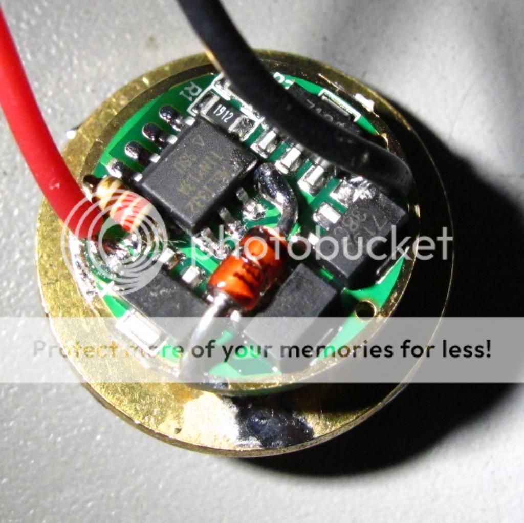
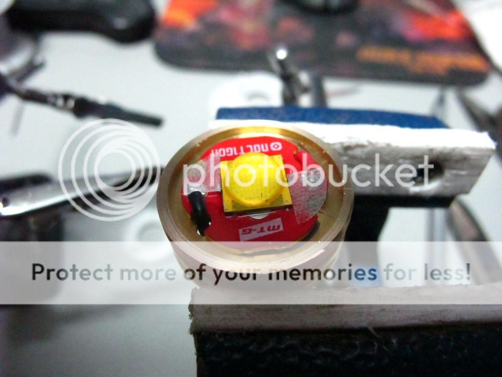
To do the Zener mod at it's most basic level, D1 is removed and replaced with a 200 to 220 ohm resistor.
This biases the MCU to run off the higher voltage of dual li-ion cells required power up the 6V MT-G2.

Then, a 4.3v Zener diode is connected from ground to the +V pin on the MCU as shown in the photo.
Alternatively, a smaller zener may be connected across capacitor C1 on the other side of the driver board as it follows the same electrical path.

The correct placement of the zener is with with stripe on the positive side, or AWAY from ground.

The 7135 regulators don't mind the higher voltage of dual li-ions but the MCU does. That new resistor connects +Vin directly to the MCU's + voltage input to power it up and is not connected to the 7135's. They are connected directly to -Vin and regulate - passing it to the LED. +Vin on the driver simply powers the MCU and passes directly to the LED.

The 200-220ohm resistor is selected based on the typical operating voltage of the batteries under load.
When the driver is put into low mode, this can cause a spike in the voltage as there is not enough load to cause a voltage sag.
This is when the zener comes in. A zener diode will "switch on" when the voltage reaches it's rating, at which point any extra voltage which may damage the MCU is bled off to ground.
4.3v is selected as it compensates for the 5% tolerance of the component allowing the MCU to operate at a 4v min to 4.5v max voltage range regardless of which way the 5% drifts.

The zener mod as seen so far at it's basic level, disables reverse polarity protection as the diode has now been removed, and low battery shut down as the MCU is now getting higher then normal battery voltage reading.

This brings us to the next phase to enhance the zener mod.

Next we will rebias the voltage divider to set a new low voltage cut off point.

IMG_0577_zpsb5f129e7.jpg


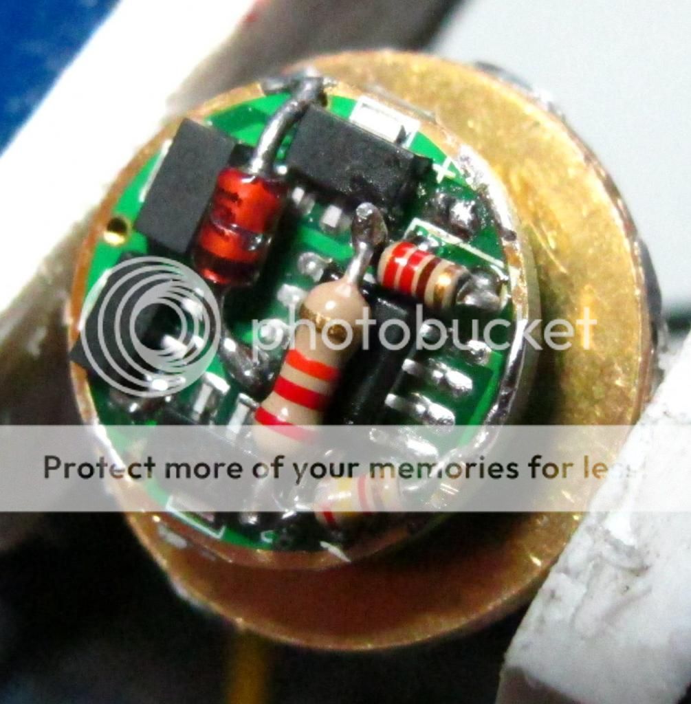
Seen here, R1 has been replaced with a 2.4k resistor, and R2 has been replaced with a 22k resistor.
Half of R2 has also been moved. It has been connected to the top of the new 220ohm MCU resistor which is connected directly to +Vin so that it can correctly read the battery voltage and is unaffected by the MCU resistor.

As referenced in the very first photo. R1 and R2 are connected together on the top, routing then to the MCU.
The Bottom of R1 connects to ground or negative in.
The bottom of R2 has been moved.

The MCU reads the battery voltage not from it's + input but from and extra sensing pin that get's it's reading from the voltage divider resistors.

R1 is the dividers shunt to ground, and R2 connects to +Vin to get the battery voltage.
Between the 2 of them a voltage output results that gives the MCU essentially and On/Off signal telling it when the batteries are low.
When the batteries are High the MCU reads over 1v from the resistors. When the voltage drops below 1v to around 0.6 to 0.7v the MCU triggers emergency low mode. When the voltage drops to 0.5v or below the MCU triggers a warning signal and shuts down.

R1 and R2 value ratios are selected to translate the desired low battery voltage into the above mentioned MCU trigger voltages.

Due to component tolerances, results may vary, however, in my case:

This ratio resulted in emergency low mode kicking in at around 5.5 to 5.6v, and shutting down at just over 5.1v, on the bench while using a powersupply.

In practice, testing with actual batteries, low mode kicked in a 5.42v.


This is just about perfect for running IMR cells that are typically rated for a minimum discharge of 2.5v/cell, and accommodates nicely Lifepo4 cells which the Zener'd MT-G2 also runs well off of.
At 2.71v/cell you will get a clear warning that the batteries are exhausted when the light drops into low mode automatically.

The components I selected were based on common availability.

Raising R2 or lowering R1 will raise the cut off voltage.
I could not find another common value for R2 that would accommodate my needs.
The stock value is 19K. There are few if any common values between that and 22k.
Jumping up to 33k raised the cut off voltage too high for me.

I chose to go with 22k and played around with R1.
A common value of 2.2k on R1 changed the shutdown trigger to about 6.4v which was too high.
As you can see, it's a very touchy and delicate balance. It took me a couple hours of experimentation to get the results I wanted.

And now, Pics or it didn't happen:

IMG_0561_zps4760f248.jpg


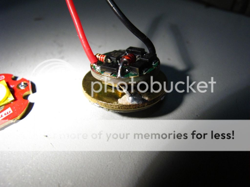
A combination 21mm contact board and brass washer are used to fit the driver module into the dropin I had to work with.

IMG_0562_zps790109c4.jpg


IMG_0563_zps94b0f2ac.jpg


The beast. Note the cutting around the edge.

IMG_0567_zps8f960a62.jpg


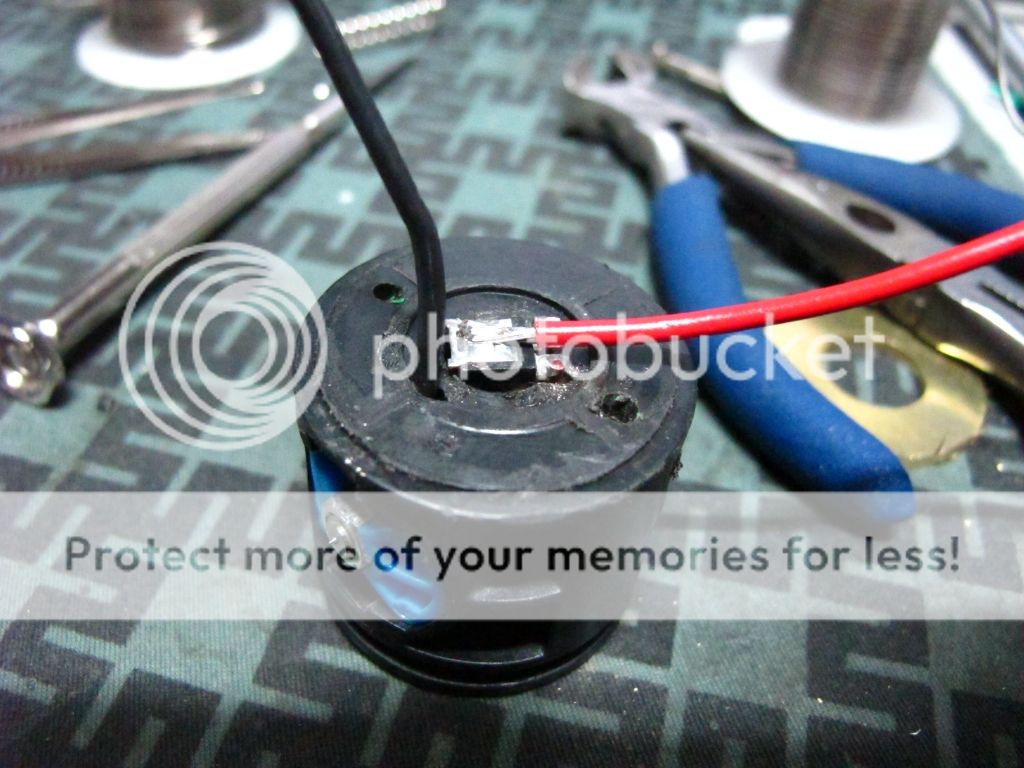
I like my FET switch mods.

IMG_0578_zpsa30bbf12.jpg


It's not pretty, but it works. I used a 52mm P7 drop in from DX.
It needed fitting. I had to lathe the edge so it would sit proper deep in the mag head.

IMG_0579_zps023df3eb.jpg


This side is pretty. I had to turn down the slug on the lathe a bit so that it would tightly sandwich the LED in place.

IMG_0580_zpsf637fb36.jpg


18g wire salvaged from a Computer PSU. I wanted to use spring contacts originally but they did not reach the top of the Mag Tower.
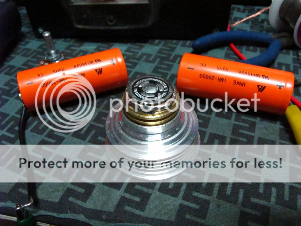
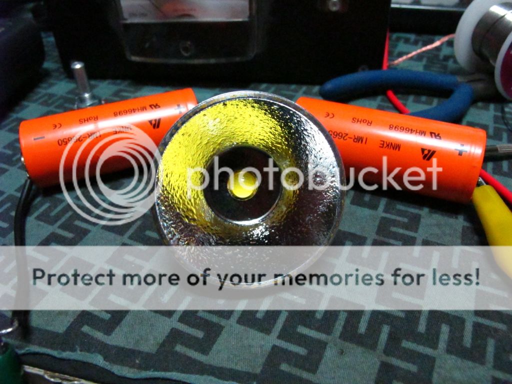
IMG_0549_zpsc35e83c4.jpg


The power plant.

Despite the lack of cooling that this dropin offers. It will run without much heat on medium for long periods of time while cranking out as much light as an XML at 3 amps. I measure 750ma draw from the tail on medium.
On high it runs reliably without any overheating issues for a solid 20mins straight.
I used thermal past on the threads that mate the slug to the reflector. It seems to do a decent job cooling the MT-G2 at it's stock 3amp draw. Overall I'm very happy and impressed with this build.
 
Last edited:

Conte

Enlightened
Joined
Dec 15, 2009
Messages
735
Location
Canada
Hmm, should I have posted this in one of the other sub-forums ?
Like in Flashlight electronics ?
 

Rod911

Enlightened
Joined
Sep 16, 2009
Messages
302
Location
Melbourne, Australia
Hmm, should I have posted this in one of the other sub-forums ?
Like in Flashlight electronics ?
More like the "other" forum.

Any way, good job. An interesting twist to a mod that I'd like to do myself eventually. The advantage of doing this to a 7135 based driver is that they are pretty robust, even up to 5A. That is sometimes more favourable, because of the unknown element of how other drivers might do when resistor modded to higher amps.

My modded big head thread saw nothing but views. Oh well.
 

Conte

Enlightened
Joined
Dec 15, 2009
Messages
735
Location
Canada
Thanks.
While running this rig, that aspect of it was bugging me, like it just wasn't complete and I had to do something about it.
Turned out to be something so simple, I don't understand why it wasn't made part of the mod by who ever originally came up with it.
It's be nice to fine tune the trigger voltages but then I'd have to get into some more oddball resistor values.

This sticks with the stock 3amp set, but I'm pretty happy with the output. I'd have to upgrade the heatsinking to get the most out of what's there already.
Some people have stacked up the driver pretty heavily.

Yeah, there seems to be a lack of comments on the basic mods these days.
 

Rod911

Enlightened
Joined
Sep 16, 2009
Messages
302
Location
Melbourne, Australia
Actually, your mod isn't that simple. Taking the time to test the right resistor takes skill and patience. I haven't taken the time to teach myself the "why" - I tend to just do the mods with some theory that it might work, and if it doesn't, find out how to make it work.

Yeah, I know that is an inefficient way to do things, but, with the help of other modders, I still make things manageable. :)
 

darkknightlight

Enlightened
Joined
Oct 28, 2011
Messages
440
Location
USA
Conte, this is a great mod! While I really liked the idea of the original zener mod for 7135 drivers to run an mtg2, I was not thrilled with the lack of low voltage protection. My experience with running an mtg2 from two cells has been that even with low voltage protection, when running on high the dimming of the light due to the batteries running dry served me well. The driver's protection was really a last ditch effort. I also primarily run this emitter in small lights with 2x18350.
In any case, your mod definitely adds a sense of security to knowing when the batteries are drained. Well done!

Edit: wow just reread my post. Not sure it makes any sense; coffee hasn't kicked in.
 
Last edited:

bshanahan14rulz

Flashlight Enthusiast
Joined
Jan 29, 2009
Messages
2,819
Location
Tennessee
Nobody mods their own lights these days :p

Seriously, though, great post. I have a very very basic understanding of electronics, and yet this post was easy to read and I feel that I could perform this mod myself and still understand what is happening in the circuit.

One thing I've noticed is that you state that the 7135 don't mind the extra voltage of 2xLithium ion, but the datasheets usually claim 6V max. If one wanted to be safe and only let the amc chips see a lower Vin, could you feed the 7135 from the same Vin of the MCU?

And in case the message wasn't clear, thanks for outlining your component selections and why you chose them, the "why's" really help me understand how these work. I now understand the idea behind voltage divider, and can't believe I didn't grasp it sooner or more easily!
 

Conte

Enlightened
Joined
Dec 15, 2009
Messages
735
Location
Canada
When I embarked on my journey to do the zener mod myself, I found that there was no "how to" thread on this sight. Not much explanation at all really.
I did a google search, and found a rough explanation on a couple other sites.

I decided it was a good idea to combine all that I knew and spell it all out here for anyone interested in doing it. It's fun project, beginner level as far as modding goes, but surgical/experienced as far as soldering goes.

That and, combine with the reflector I found, for my purpose it makes an easy way to breath life into an old m*glite.
I've noticed a few "what to do with an old 2D m*g?" threads in the last month.

The funny thing is, I'm a technician by trade, so when I researched the circuit, I understood completely how it worked and why certain components were chosen. However, I am not an engineer and could not design this myself. I didn't know the math, so instead if calculating the values I needed to set the low cutoff, I had to spend a couple ours doing good ol' component sub trial and error. |

Darknight' : I hear ya' I've noticed that the LED gets rather dim before the low voltage kicks in. Mind you, I also found ion practice, when using it constantly for a long period of time, as it dims, my eye adjust and I don't notice it's going down until just near the end. One application I was considering, is that if you needed all the runtime you can get, you can still get usable amounts of light right down to the last mah.

I'm thinking of grabbing some other values and maybe bumping the cutoff up a bit, setting it to cut off before the light starts to dim.

Bshanahan': There is an anomaly in the datasheet. In practice, the 7135's don't seem to mind. I've ran the light for hours and they aren't complaining.
The way I understand it, is if you actually implemented the 7135's as adjustable regulators using the typical methods, then they would fuss over the voltage, cause if you make them drop a voltage while running them over their rating, they will heat up quickly and fry.

However, these drivers run them in a PWM fashion like a FET driver. They are either on or off, passing full voltage and are not required to actually voltage regulate. Run them wide open in this fashion puts little to no stress on them allowing them to handle the higher voltage.

To answer you question, as I'm understanding it, if you fed them the same voltage as the MCU, you'd effectively be running them as stock defeating the purpose of this mod. In case you are unfamiliar with the MT-G2, it's a high voltage LED, running at 6+ volts as opposed to the usual 3.3-3.5odd volts the XML and other leds run at. The point of the mod is to jack up the drivers voltage handling to run this LED.
 

mom4ence

Newly Enlightened
Joined
Dec 25, 2016
Messages
3
Hi,

If made R2 higher than 22k , cut off will be on highest voltage ? I want cut off to be on around 2.8v

And did I correctly understand your scheme for Zener Mod

Zener_Mod_Rev3.jpg
 
Last edited:

Latest posts

Top