Lens Shapes, Optical Arrangements, and high-Kcd Throw

matt304

Newly Enlightened
Joined
Sep 28, 2006
Messages
183
I came across a lens which is absolutely destroying my others lenses of similar shape/size/FL. It is approximately 83mm x 90mm FL.

What is different about this lens, is that it is an aspheric lens, with a convex backside, or a radius on the side which is typically plano in other words on an aspheric lens. With all of the aspherics used on the site and in builds, they all tend to be plano-aspheric (LED-side is flat) I've noticed. My best performing 80mm x 60mm FL lens reaches 350Kcd with an XP-E2 driven mildly. This other "aspheric-aspheric" lens, with an even higher F/#, is reaching 460Kcd with same LED (all measured at 10 meters).

What surprises me is the fact that it has a curved side facing the LED. I've never heard this to be recommended, or seen used for an LED lens. Do I happen to have a very high quality lens on my hands, or could its shape be part of the reason the Kcd is so high?

The other lens I have for testing is an 87mm x 100mm FL aspheric, and although the beam is smaller and F/# slightly higher, it only reaches 285Kcd. It is however closest in overall specs, and is ground not cast. But from 285 to 460Kcd is a massive jump in my testing for similar lenses.

Lenses are table mounted when tested and are still. Whole emitter surface is used for light reading. Any ideas or thoughts on this type of lens design? I was considering using a smaller aspheric mounted very near the LED as a method of condensing the initial beam of light to gain higher Kcd yet.
 

sven_m

Newly Enlightened
Joined
Jul 11, 2009
Messages
100
Location
Southern Germany
There might be some slight advantages for a lens which is plano-convex or even concave-covex (meniscus),
- less chromatic aberration (much more important for imaging systems, though), i.e., slightly less color fringes
- less reflection loss for light far from the optical axes due to less steep refraction angles

1. But by far the most important part for max-lux is the quality of the lens.
And there's even a relatively simple way to check that:
Look at the apparent illumination of the lens from the exact viewpoint of the spot
(dim the LED or use filters)

You'll notice that the lens isn't completely illuminated especially for small LEDs.
This is mainly due to a bad curve/quality or also due to bad focusing.
You'll notice that it's everything but easy to perfectly focus small LEDs.
If half of the apparent lens area isn't illuminated, half of the lux will be missing.

That means bigger LEDs can balance for a "bad" lens quality.
And small pre-collimators also do, because they increase the apparent size of the LED for the bigger lens.

2. Last but not least, the effective optical diameter is important, the diameter of the actually curved area.
Some lenses have quite big "borders" (for holders). This can make a difference, as diameter is crucial for max-lux.
You mentioned 87 and 80mm. If both were ideal lenses, the 87mm one would yield 18%(!) more max-lux (87²/80²=1.18).
If you want to compare slighly different lenses you could also adjust the diameter with a paper ring on the flat side.

Focal length in turn doesn't matter for max-lux, but for spot size ("usability").
 

magcharger101

Newly Enlightened
Joined
Dec 25, 2012
Messages
32
First off I'm a novice to all this stuff. But I read about some lights with aspherical lens in them. I have a nitecore MH25 I'm thinking about putting one of those lens in. All I'm interested in is just throw. Would that work or be a mistake. I haven't found very much info on these lenses. Thanks


Sent from my iPhone using Candlepowerforums
 

matt304

Newly Enlightened
Joined
Sep 28, 2006
Messages
183
Focal length in turn doesn't matter for max-lux, but for spot size ("usability").

My understanding was that what you're saying in that quote is mostly true, to a degree. Here's what I have gathered from research: FL does in fact matter towards lux, with all else being equal, and there will be a non-linear curve in lux output as a certain F/# value is reached and passed higher or lower in either direction. Say starting at F/# 0.4 and moving through F/# 0.9, there will be some F/# in between that range, theoretically, that does in fact reach a maximum lux output value. So, starting with an F/# 2.0 at same diameters, the spot size will in fact be smaller than a 0.5, but the lux value will have probably fallen off as well. As the optical design scales larger though, and larger objective lenses are used with longer FLs and larger F/#s, such as a 200mm diameter x 400mm FL F/#2.0, the light can be more easily condensed from a beginning asphere near the LED and larger F/#s start to become more effective as the diameter allows them to work with more readily available aspheric lenses to be used as condensers, landing more total light on the final lens. For instance, a light I came across one day sort of demonstrates this I would say (Huygens Ultimate): http://www.candlepowerforums.com/vb...-Huygens-Ultimate-1-800-000-candela-Led-light

Anyways, what you speak of otherwise, is what already sort of made sense to me, which is why I couldn't believe the lens performance. The lens was tested with a meniscus lens, limiting the input aperture. So it actually produced a much higher Kcd value, gathering from a 60mm meniscus lens. The same meniscus lens didn't improve the performance of the plano-cvx lenses. But yes, the rear of this high-end aspheric lens is a convex, not a concave (cvx-asphere in other words, or possibly even an asphere-asphere; I can't quite make out the shallow curve on the rear to be aspheric or convex because it is not extreme, probably 5mm outward curvature starting at the lens edge). So, the ray incident angles entering the lens are in fact greater from the LED source, leading me to believe the gathered light would be less, and refraction would be greater, resulting in less output lux than the other two lenses. But, the lens is coated I noticed; a bluish, dim reflection appears rearward with LED near the lens and powered up.

I will post some pictures later of the lenses so you can see what I am working with. I have moved onto using a de-domed XP-G2 mounted to an aluminum block on a copper sink-pad, with a 25mm effective lens diameter, glued close to the LED as a small-condenser lens. I found it to be a better condenser than a longer FL lens mounted close to the LED. The output circle is smaller on the wall vs a slightly longer FL 25mm diameter asphere I noticed, and thus more light falls onto the 80mm+ objective lenses. Both condenser lenses that were swapped out were mounted about 4mm from the LED die to capture the most light possible (stopped by the mounting screw heads for the sink-pad). 4mm is also well under each 25mm condensers FL, so light axis is not inverted to the second lens--a virtual image exists. My next plan is to attempt to use a very high quality 50mm aspheric lens, at the same 4mm from the die front, in hope of better condensing, but the lock ring is jammed in the bezel until I make a tool to unthread the lens out from the current bezel body. That way I could compare different ratios of condenser lens diameters (25mm vs 50mm) against the same objective lenses to find the real result of this condensing effect.

I will say that so far, as far as lux goes, multiple lenses appear to be beating the use of single objective lenses placed at FL from the LED (the common, LED+asphere method).
 
Last edited:

sven_m

Newly Enlightened
Joined
Jul 11, 2009
Messages
100
Location
Southern Germany
Here's what I have gathered from research: FL does in fact matter towards lux, with all else being equal, and there will be a non-linear curve in lux output as a certain F/# value is reached and passed higher or lower in either direction. Say starting at F/# 0.4 and moving through F/# 0.9, there will be some F/# in between that range, theoretically, that does in fact reach a maximum lux output value.

What theory is connected to this theoretically?

Do you mean your own research? I haven't made any experience like this until now.
Unfortunately, it's complicated to make reasonable experiments in a way that can be reproduced by others.

And how might "Huygens Ultimate" support the idea that FL matters in your opinion?
(WalterK does not think so, btw.)

I know that some CPF members believe that FL matters, but I don't.
I would really like to hear about a plausible physical idea behind FL influencing max-lux.
Until now I only know an idea which contradicts it (conservation of etendue).
 
Last edited:

m4a1usr

Enlightened
Joined
May 4, 2013
Messages
884
Location
Washington State
Matt304

Can I ask where you have found your convex backsided lens? I have been pushing a Aspheric build along very slowly and learning as much as possible during the experience but wouldn't mind absorbing others lessons.
 

PeterH

Newly Enlightened
Joined
Aug 31, 2010
Messages
52
A shorter focal length lens can capture more light from the source. But a finite size source has a larger angular size from the lens' perspective as it gets closer, limiting how tightly that light can be projected.
 

matt304

Newly Enlightened
Joined
Sep 28, 2006
Messages
183
What theory is connected to this theoretically?

Do you mean your own research? I haven't made any experience like this until now.
Unfortunately, it's complicated to make reasonable experiments in a way that can be reproduced by others.

And how might "Huygens Ultimate" support the idea that FL matters in your opinion?
(WalterK does not think so, btw.)

I know that some CPF members believe that FL matters, but I don't.
I would really like to hear about a plausible physical idea behind FL influencing max-lux.
Until now I only know an idea which contradicts it (conservation of etendue).

This actually seems so simple, that I'm not sure why this isn't brought up more often. Unless my outlook is completely off, in which case if it is, someone would be very helpful to explain why what I am about to explain would not be true in practice.

I will skip the obvious things which I think conflict with LED use, and lux (throw) in the real-world use of available lenses. Remember, these are real lenses we use, not infinitely-thin proposed lens planes using infinitely-small point sources for calculation of collimation angles. An LED is not a point source. It has a real size. It also has a characteristic pattern of light output!

While light, in general, follows very specific rules, an LED is a device. The way it emits light is not equal in all directions. Because it is not infinitely small, and has a size, it also has something CREE themselves take the time to document in their PDFs.

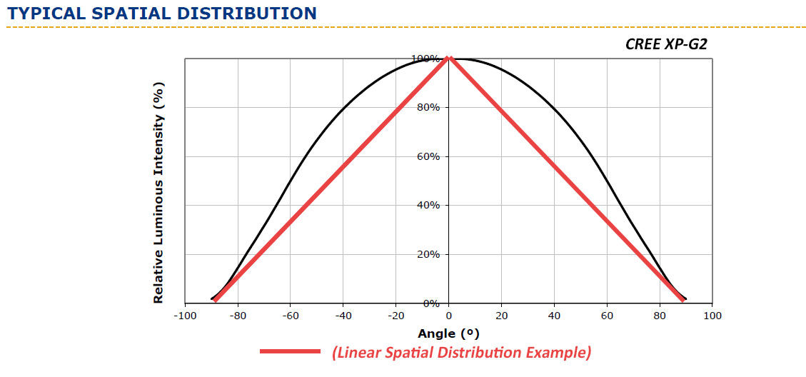
Let's talk about "Spatial Distribution". First let me make things clearer as to what point I'm arguing.

Argument #1:

Two lenses of different F/#s are the same diameter and surface area on the side facing the LED which is also plano (flat) on that side. The lenses are of the same quality, yet their focal lengths vary. One person says, at the same diameter and light entrance area, the same amount of lux (throw) is constant between these two different FL lenses. The only thing different (for arguments sake, I'll keep it simple here) is the output angle of the beam ahead of the lens. The lower F# lens (shorter FL) yields a larger projected square output. The higher F# lens with longer focal point yields a smaller projected square. But, both lenses throw the same distance. That would make the lower F# lens more efficient of course, because it is covering a larger projected output area with the same intensity of light per area covered.

Argument #2:

In the real world, lenses of equal diameter but different F# can have an influence on throw, even though argument #1 may be accurate in "thin-lens" equations. However, argument #1 holds truer when a point-source is used as a light source, and therefore it is not a perfect analogy to use when an LED is used as the light source. Although the general laws of point-source light are accurate for argument #1, an LED is not a point-source, and it emits light in a semi-known pattern known as "spatial-distribution". Because spatial-distribution of angular light does not adhere to a standard law that we know as applied directly to LED output, it is assumed that a circle which captures light (a lens), must also not adhere to the general laws of light gathering when the source has a specific spatial-distribution. If we even attempt to assume that lenses obey a standard of light-gathering based on initial angle of light incidence and lens area, when the angle of intake light changes, we find that spatial distribution itself is what throws a curve ball into the mix.

Okay, so what is the curve ball?

Different F# lenses capture light at different angles from the source, keep this in mind foremost. This means that different F# lenses rely on spatial distribution of light, to predict gathering of light at any given intake angle! General area formulas for circles, and triangulation formulas, must take into account the spatial distribution of the LED, because the LED must be treated as an optical system itself coupled to a lens, not as a simple 1-dimensional object that is illuminated and viewed through a lens.

To better illustrate this problem I see, a simple diagram should help clarify everything. :)

IO3mCcR.jpg


Now, I am keeping in mind that my example image is only an attempt to display what "linear" distribution actually is as I somewhat conceive it to be. However, this image is more or less there to show that for a given LED, the light captured at a different angle is not a constant, it is a sloped curve that varies. (If the graph were to show 180°, a sphere might demonstrate this more accurately than a triangle.)

Moving on, if a lens is close to the LED and having a lower F#, a given distribution of light is captured. If a lens is further from the LED and has a higher F#, another given amount of light is captured, but we cannot concisely predict them using a general inverse square rule, as that would be acting on a linear spatial distribution of light . In conclusion, due to spatial distribution, nothing can tie these values together as "predictable", without a formula that incorporates the spatial distribution profile into the lens(es). Since the profile is not a standard shape, like a cone or a half-sphere of light, F# means that lux must change, at least somewhat, as incidence angle changes upon the lens face.

All of this, and yet still before even acknowledging that real lenses (not thin imaginary lenses) with large face radii have troubles collimating the light at the high interior angles found closer to the outside of the lens face surface; where light is highly bent. A high F# lens does not capture as much light as a much lower F# lens--that can be said, but it also doesn't suffer from as many internal refractions/reflections as the lower F# lens. In my opinion here only, it seems that some F# within a range of F#s must be most efficient at lux output and therefore throw, at equal lens diameters.

I am eager to know how spatial distribution would NOT effect throw/lux in varying FL positive lenses of equal quality and diameter. :)
 

matt304

Newly Enlightened
Joined
Sep 28, 2006
Messages
183
I have been testing optical arrangements, combined with light-recycling collars and without. The collar of course allows the system to become more compact, diameter-wise in some lens configurations (of lower F# mainly), because the collar effectively is an aperture ahead of the LED. So a smaller, defined path of light leaving the front of the collar exists. In that configuration, doubling the lens diameter, at the same FL distance will not double the diameter of lens surface area impacted by LED light, as it would if no collar was there. Luckily there are gains in the collar system to make up for the aperture effect to overcome it. Hence the DEFT-X...very high-Kcd without a very large aspheric lens diameter. I have not had this spec confirmed, but from photos that I've pixel counted and knowing the host dimensions, it appears the DEFT-X uses only about a ~55mm aspheric lens. If someone could confirm on that it would be great.

The aperture effect is most pronounced however with the smallest recycling collar, having a 12.5mm exit hole above the LED chip. A big host is needed that can fit a larger (60mm+ optical system to fully benefit from the medium size collar).

De-doming serves a purpose to increase candela/LED surface intensity as we very much can agree on. So you might wonder why you would ever add a lens again, after de-doming, with that lens very near the LED. It is because the domed factory LED lens is so small and of low surface quality that refraction losses and scatter tend to outweigh the collimation gains of that plastic, molded lens. The lens does decrease initial beam angle since the LED image grows larger in perspective when viewed through the dome, but the dome doesn't pair as well as better quality, bigger lenses right in front of the LED of course, before the primary collimation optic.

With those things in mind, I am seeing huge gains in lux/throw, when high-grade AR coated meniscus lenses are used not only before the primary aspheric lens, but also after the primary aspheric lens. A meniscus lens of smaller diameter and low power (long-FL) before the aspheric, combined with a slightly higher power (lower FL) meniscus lens placed AFTER the primary focusing optic is showing big lux gains of 20-30% or more in some cases. In fact, it appears the lens placed ahead of the primary aspheric is actually more important than the lens placed behind it!

It is a 3-lens condensing system, in other words. Light is bent gradually inward at meniscus lens #1, which is effectively landing more concentrated light on the aspheric (lens #2)--light that would normally be lost outside the aspheric lens, and after near collimation by that aspheric lens in the middle, a final gradual bend of light occurs at (meniscus) lens #3 to bring all 3 lenses into sharp focus of the LED image. So the light steps to a larger diameter at each lens passing, with light being bent or focused most at the middle lens. The front exposed meniscus lens is the largest diameter lens in the 3-lens system. These are high-quality VIS (400-700nm) AR-coated meniscus lenses that are unavailable for order now I'm told. My good friend has a supply of these lenses through a precision optics run he obtained long ago at a lab in the mid 1990s, and he allowed me to pick up quite a few from him for a trade. The specific lens models are now discontinued and no longer used I'm told. The aspheric used in the testing is NOT coated, but is precision ground glass of 60-40 or possibly even higher quality, but visibly much clearer than 80-50 dig by comparison to other lenses of this known value. I am not sure how to definitively test that surface grind quality with home equipment, other than that I can visually see they are extremely smooth reflections when viewing internal surfaces through a 5x loupe.

Anyways. What is my conclusion here? Nothing new to commercial imaging industry of course--more, correct lens elements shaping light into collimation in steps, appear to always beat one single lens doing all that bending in one step, even though a small percentage of transmission is lost through each of more elements. More LED output light is actually brought into collimation IF the optical cavity space exists to use such a configuration as the focal space tends to be a bit longer than in an LED-to-single-lens coupled system.

I will next be attempting to integrate this, or a very similar collimation system into a large handheld host head, one which has a very large optical cavity compared to any of the other hosts I have found, except maybe a BTU Shocker or possibly, a Supbeam K50. The host I chose and designed for this purpose, is being CNC machined now, and will therefore be a custom host head once done.

Optical arrangements for it will be tricky to integrate like this I know, but will give it a try with the help of CNC and 3D-printed spacers. It works on the bench with high success over the THOR 75mm-60FL (7560) aspheric, and Edmund 80mm-59FL aspheric, as far as lux output is concerned, just need to fit the elements in a proper host ahead a recycling aperture now.
 

sven_m

Newly Enlightened
Joined
Jul 11, 2009
Messages
100
Location
Southern Germany
That's quite some text and various aspects. Honestly, I'm not sure which points I should pick up to bring our issue further.
In the following I put keywords in bold face, so it's easier to read and to distinguish between different issues.

But first of all let me say, that I'm talking about real-world effects, too. I'm not having any special effects in mind which only apply to theoretical corner cases like point sources and ideal lenses.

Spatial distribution took quite some room in your arguments.
Although I'm not sure if I have fully understood you, I'd like to pick this up because I strongly believe that the spatial distribution doesn't matter at all (!) for the "focal length vs max-lux issue". Why that?

In the following I have a dedomed LED in mind, that is, a flat square. (An LED with dome has a slightly different light distribution. But that only complicates calculations, it doesn't add any new effect.)

The spatial distribution has this curve (instead of a constant 100%) only because the led seems to have a smaller apparent "height" if you look at it at from the side instead from above. (The width doesn't change.) And from 90° to the side, it becomes almost invisible (an incandescent or an HID source doesn't have this curve, here it's just a line at 100%, over 360° even).
That's it. Only the apparent "diameter" of the LED is changing. For the dedomed led this curve is simply the cosine function, because the apparent length of a line at different angles is somewhat the definition of the cosine.

In contrast, another elementary measure of the flat LED is not changing towards higher angles: the luminance ("surface brightness").

Now my point is that the diameter of the LED doesn't change max-lux for a good lens.
Only surface brightness does. If we can't agree on this point, than there's no point in moving on to more complicated scenarios.

The spatial distribution of a source usually is most helpful if you make plain usage of the source and light up a surface with it (wall, room, street, etc.). That is, if no further optic elements are involved. It just tells you how many lux are produced at some other point by the source as a whole. If you add further lenses or mirrors it gets extraordinarily complicated to calculate with it, the curve is not helpful anymore.


You mentioned that lenses with high diameters might have trouble at their outer parts due to reflection/refraction losses.
This is true, more light is reflected instead of transmitted at high incident angles (so at the outer parts).
But it's usually not of concern for us. It's described by the fresnel equations. It's difficult to calculate with them, because you have to take account for the polarization of the light. However, there's a way to simplify it a lot, using Schlick's approximation. Uncoated glass usually reflects ~4%. The approximation shows that this doesn't change significantly until the light hits at 60° instead of 0° (vertical). 7% are reflected then, and 10% at 65°. Yes, that's an unexpected result. But it means that this problem doesn't apply for the aspherics we use.

It seems we also have gotten different results in our experiments, but that doesn't help our discussion,
because we can't see the other side, respectively, and where we might beg to differ how to conduct the experiments.

Finally, you mentioned the effects of a precollimator. My problem with bringing in this optical element is this:
I strongly believe that it only increases spot size and catches more overall lumens.
Given a good lens, I see no way for it to increase max-lux (again: I'm speaking about real-world lenses).
However, if the lens is too bad for the source (or if the source is too small for the lens, if you like),
then it can compensate for the lens, because it magnifies the source.

There's an easy way to explain what I mean with that:
Look back at your lens+source from the very location of the spot. If the lens is not illuminated completely, then you'll get less lux than possible. Either it's not well focused or your lens is bad. If a helping person tries to focus while you're looking at it from the spot, you'll immediately see how difficult focusing can be for small sources. There are always darker zones and rings in the otherwise illuminated lens, some lens areas just seem to be missing the LED, and moving the led fills one hole and opens another one.
With a precollimator however, such a lens is completely illuminated, focusing is much easier and you'll get max-lux again.

I'd like to say it this way: You're not winning any lux with a precolli. You just had missed some lux without it. That is, in case the lens or the focus was not good enough.


Conclusion? I can't imagine which of the above arguments are helpful for you or others. Perhaps we eventually might just agree to disagree. However, I tried to focus on key points in the chain of conclusions, perhaps this helps to pin down the discussion to some basic things, easy to concentrate on.
 
Last edited:

TEEJ

Flashaholic
Joined
Jan 12, 2012
Messages
7,490
Location
NJ
You guys are sort of talking about aspects of the same thing but seem to be on different pages?

Was the question about why one aspheric might work better than another?

Did it segue into a theoretical physics discussion?

I typically think of it like this:

Givens = two different lenses, one produces a higher cd.

I did not see evidence to describe the spacing of the lenses relative to the emitter...as the distance from the emitter always impacts collimation. When I am trying a new lens combo...I start by holding it at the LED, and gradually bringing it farther from it until the beam on the wall is improving, and, eventually, I see an optimal distance for that lens with that LED.

So the photons hit the inside lens surface and are bent....and then the outside where they are bent again. The curve of the two sides will be more optimal for some emitters and distances than others.

One of the two lenses worked a lot better, so, that one was more optimal for this combination.

I'd repeat the experiment with as different an emitter combo as possible.

DID you try different distances from the emitter?


Other things that tend to matter - the quality of the glass and its transparency. Some lenses simply don't let as much light through for example. The order of magnitude observed would be a bit high for simple opaqueness though.
 

matt304

Newly Enlightened
Joined
Sep 28, 2006
Messages
183
SVEN_M,

Great post! I see both sides of where we are viewing from. IT CAN GET COMPLICATED! (If we want to predict an outcome to a high degree of accuracy.)

With that said, I completely understand the logic behind taking it at face value; we have a square turning into a line, as angle of incidence increases while viewing the source from ahead, moving down to a side view. From a 45° to a side, a different shape occurs, but eventually still turns to a line. Okay, I can agree with this, spatial distribution aside, as it does complicate what's going on if we are to include it in calculation, so I will just say that it's probably easier to remove it from thought processes. I thought that it might depict something else happening, when combined with a lens, is all.

The collimation through multiple lenses adds a lot of variables to talk about, so I am basically using one set arrangement, in which I remove one or the other, or both meniscus lenses, and I find that lux grows when they are all used in conjunction. The spot does grow bigger as each is added, since more positive focus light bending occurs with those extra lenses, but without them the "good" lens just acts like another medium-quality lens. Lux is boosted greatly with them, and that's all I know of this particular arrangement. So, I'll leave it at that. :)

TEEJ,

I'm hanging a bit on the idea that you ask, "DID you try different distances from the emitter?", because I am wondering if you are simply talking about focal length. If you are, it's a given that we must focus a lens properly to the LED!!

Or am I missing something?

The distance of the meniscus lenses are fixed behind and in front of the aspheric, but the system comes into focus just as 1 single lens would come into focus. As the LED moves closer to the middle aspheric lens, an image forms. This happens at roughly the same distance with or without the first meniscus (couple mm of difference yes), the first lens just gets the opportunity to join in the free space in between aspheric and source. This image is much brighter using the front, large meniscus lens ahead of the aspheric. So it's almost as if I am using a precollimator, and a "post collimator". That's as best I can describe it, although really the 3 lenses are acting like one single lens, when combined, but the light capturing process seems to be much more efficient this way, as light is bent across 6 incident angles (the total lens faces), in steps towards final collimation.
 
Top