HKJ
Flashaholic
[size=+3]Charger Opus BT-C1000[/size]
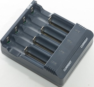
Opus makes a couple of different chargers, this charger here is a 4 channel charger that can charge both LiIon and NiMH batteries and it is possible to select between two currents.

It got this charger in a plain white cardboard box, probably because the real box was not finished yet.

The box contains the charger, and a power supply, with this early version the manual is missing.
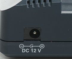
The charger has a 12V input that is used with the supplied power supply.
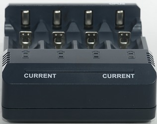
The user interface is a read and a green led for each slots and a long bar, the bar hides two buttons, one in each side.
The red led is on when charging.
The green led shows charge rate after a press on the bar (Fast flashing:1A, slow flashing:0.5A), when the charger is in the CV phase it flashes and when charging is done the light is steady.
Press once on the left or right side of the bar to show the current selected charge rate for the two left/right channels. Press again to change the charge rate.
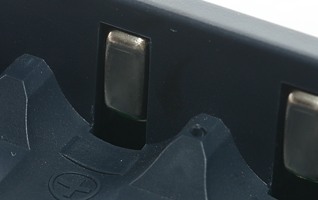
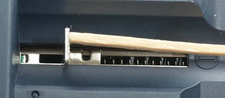
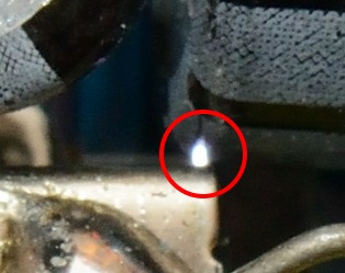
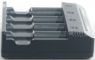
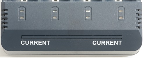
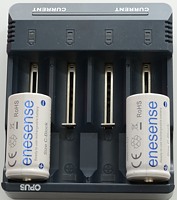
The slots uses the usual construction and works well. They can handle batteries from 34mm to 74.9 mm long. This is longer than any xx650 batteries one the market, even the extra long ones (Very nice).
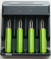
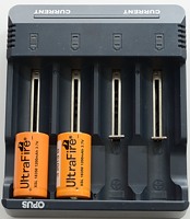
The charger can handle 74 mm long batteries, inclusive flat top cells.
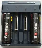
The charger is not rated for C and 26xxx batteries but they do fit into it and the current is acceptable.
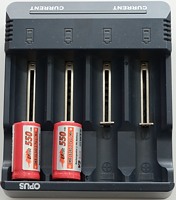
The current is too high for 10440 cells, except IMR types.
[size=+2]Measurements[/size]
[size=+1]LiIon charging[/size]
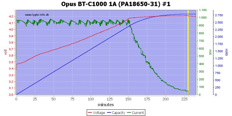
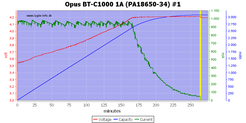
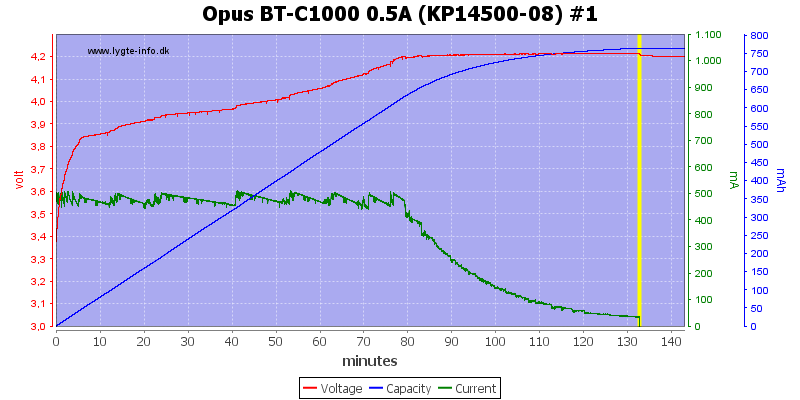
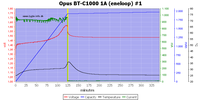
This looks like a nice CC/CV charge with a 50mA termination, this is fine.
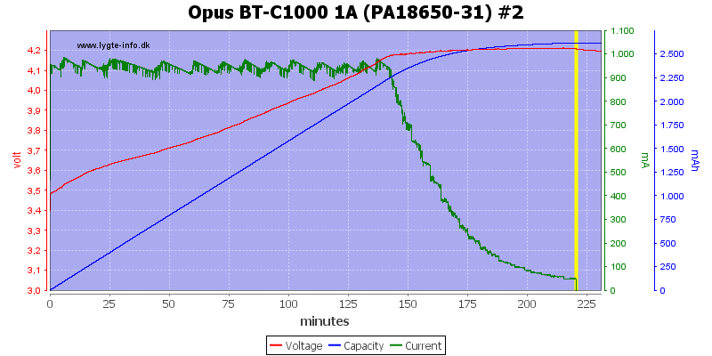
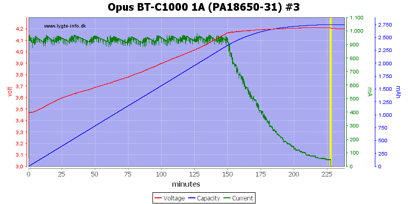
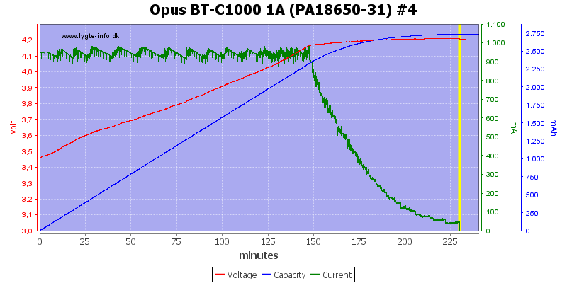
The other channels has the same CC/CV curve.
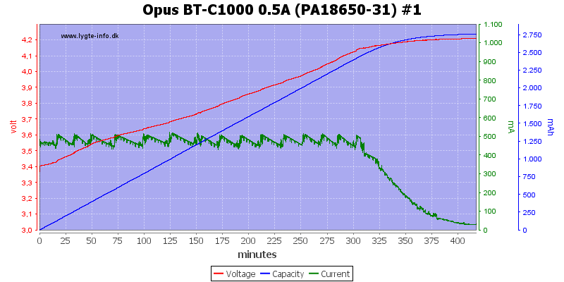
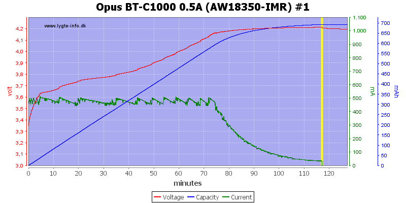
The charge curve is also good at 0.5A, the termination current has been reduced to about 30mA.
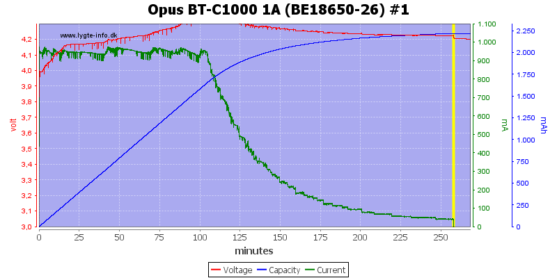
This cell do not look very good and reveals that the charge is a simulated CC/CV curve (The problem is a fairly high internal resistance in the battery, this spoils the voltage regulation with a simulate CC/CV curve).
Also note that the final voltage is within allowable tolerances.
With a better cell the curve looks fine.
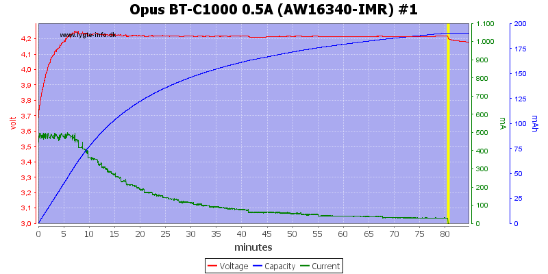
Surprising enough the charger handles this old cell perfectly.
These two are also handled perfect.

The charger can charge with 1A on all 4 channels, but it do get a bit warm.
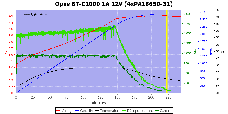
It uses about 1700mA from the power supply.
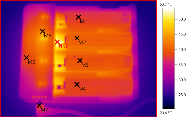
M1: 37,6°C, M2: 40,4°C, M3: 39,3°C, M4: 37,6°C, M5: 42,3°C, M6: 38,9°C, M7: 37,2°C, HS1: 53,7°C
The batteries are not to warm, placing the batteries away from the front may help in that regards.
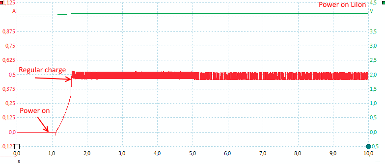
The charger will start very fast when powered on, it does not wait for current selection, but start at the lowest charge current.
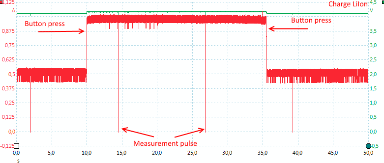
The current can be changed at any time, usual with two presses on the button (One to show the selected current, next to change it). There is no ramp when changing current.
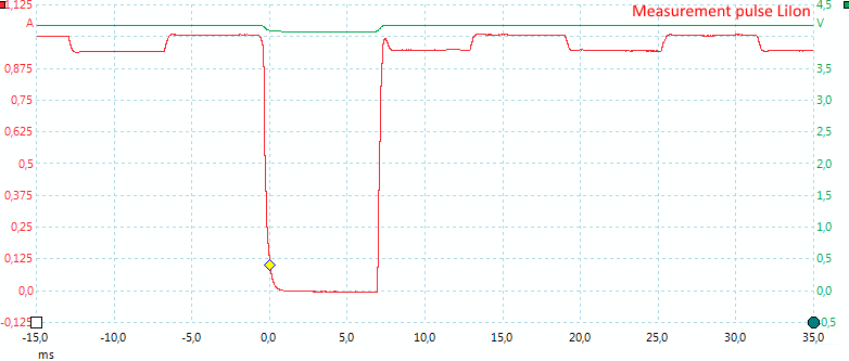
The charger has some small pauses when charging, this is measurement pauses for the simulated CC/CV charge.
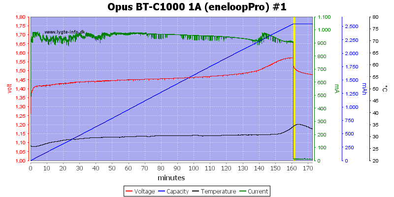
[size=+1]NiMH charging[/size]
This is a -dv/dt charging, when finished it switches to a 10mA trickle charge.
The trickle charge is a steady current, not pulses.
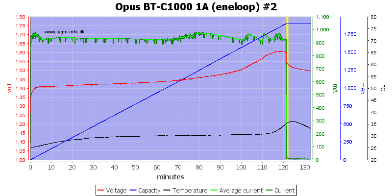
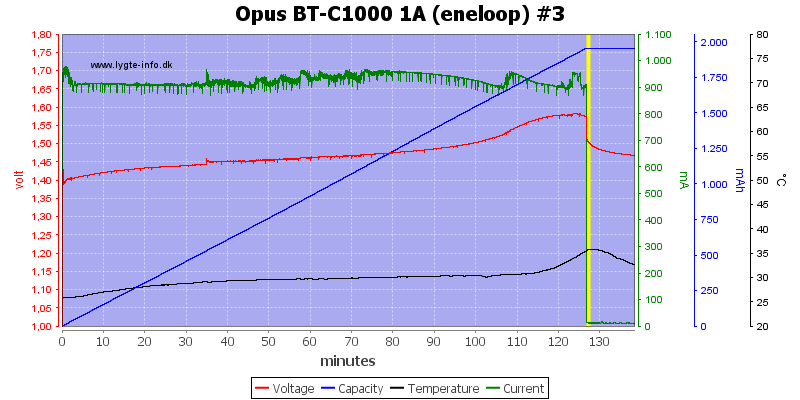
The 3 other channels looks the same.

0.5A do also charge and terminate fine.
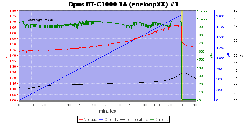
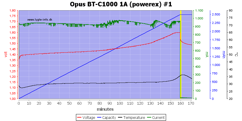
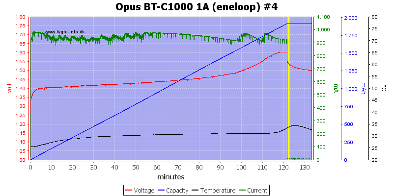
No surprise with the 3. high capacity cells, they all terminate fine on -dv/dt.
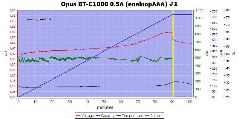
Same with the AAA cell.
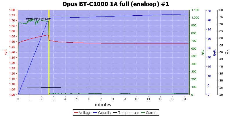
For a -dv/dt charger it is very fast to detect a full battery.

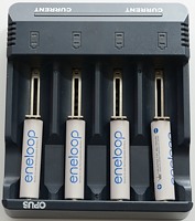
No problem charging 4 cells at 1A.
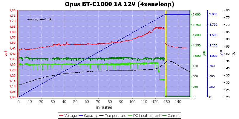
About 0.8A is needed from the power supply.
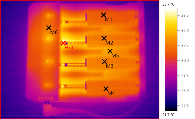
M1: 31,3°C, M2: 32,6°C, M3: 32,7°C, M4: 32,0°C, M5: 33,8°C, M6: 32,4°C, HS1: 38,7°C
The NiMH cells are not very warm during charging, but they will warm up for a short time during termination (Above picture is not from termination).
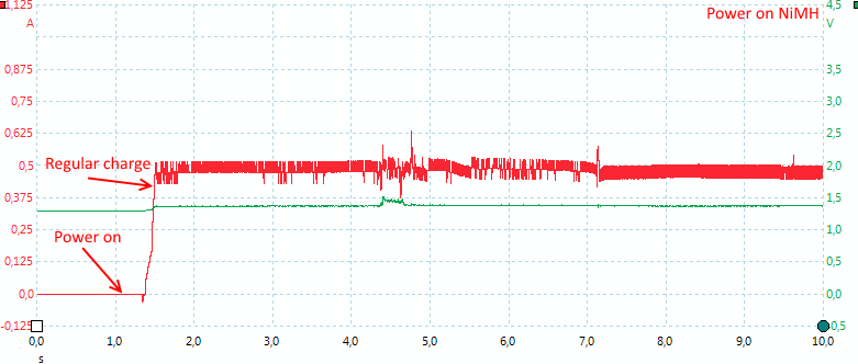
The charger will also start very fast with NiMH batteries.
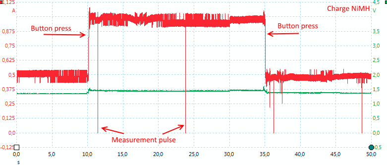
The current can be changed at any time, usual with two presses on the button (One to show the selected current, next to change it). There is no ramp when changing current.
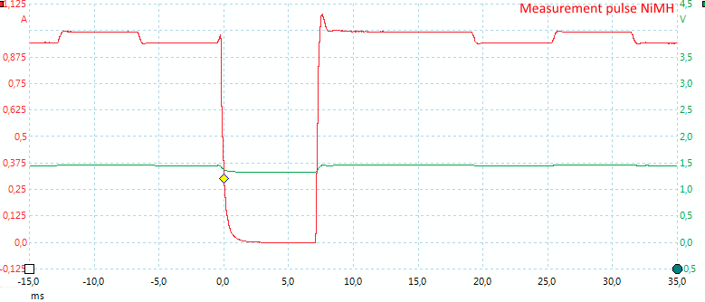
The charger has some small pauses when charging, this is measurement pauses to detect the -dv/dt signal.
[size=+1]LiIon+NiMH charging[/size]
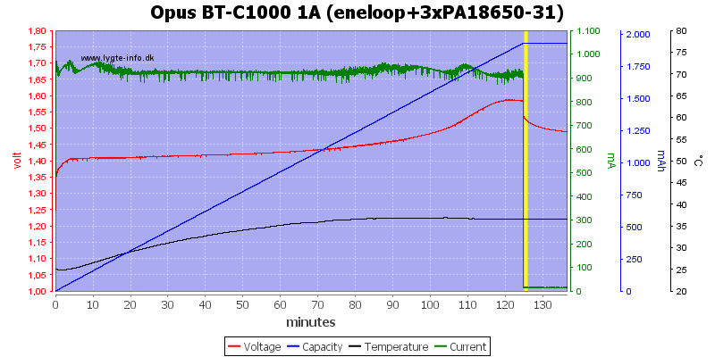
With one NiMH battery and 3 LiIon batteries, the charger has no problem with charging the NiMH.
As usual the thermo sensor is on another battery.
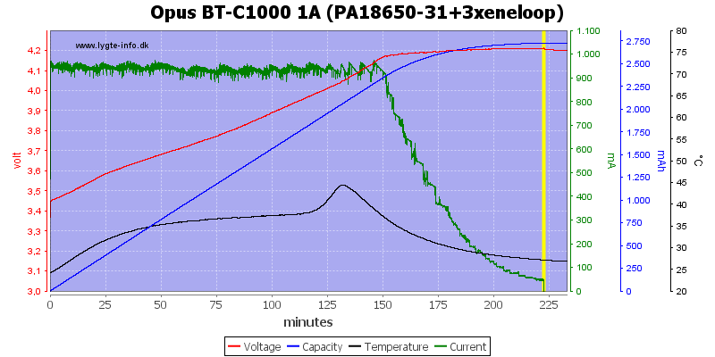
One LiIon and 3 NiMH works just as fine.
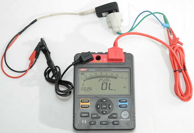
Testing the supplied power supply with 2500 volt and 5000 volt between mains and low volt side, did not show any safety problems.
[size=+2]Conclusion[/size]
Generally the charger does a good job with both LiIon and NiMH batteries and it keeps fairly cool while charging especially NiMH. The user interface works, but I prefer something where I directly can see the charge current, not where I have to evaluate a flash rate.
Indicating when batteries reach the CV phase can be useful if you need the batteries fast and do not need them fully charged.
The BE18650-26 cell is a problem, except for that I will call it a good charger. The best solution is to not use 1A charge current on old cells or only charge protected batteries.
That means the final result is an acceptable rating.
[size=+2]Notes[/size]
The charger was supplied by Opus for review.
Here is an explanation on how I did the above charge curves: How do I test a charger
Opus makes a couple of different chargers, this charger here is a 4 channel charger that can charge both LiIon and NiMH batteries and it is possible to select between two currents.
It got this charger in a plain white cardboard box, probably because the real box was not finished yet.
The box contains the charger, and a power supply, with this early version the manual is missing.
The charger has a 12V input that is used with the supplied power supply.
The user interface is a read and a green led for each slots and a long bar, the bar hides two buttons, one in each side.
The red led is on when charging.
The green led shows charge rate after a press on the bar (Fast flashing:1A, slow flashing:0.5A), when the charger is in the CV phase it flashes and when charging is done the light is steady.
Press once on the left or right side of the bar to show the current selected charge rate for the two left/right channels. Press again to change the charge rate.
The slots uses the usual construction and works well. They can handle batteries from 34mm to 74.9 mm long. This is longer than any xx650 batteries one the market, even the extra long ones (Very nice).
The charger can handle 74 mm long batteries, inclusive flat top cells.
The charger is not rated for C and 26xxx batteries but they do fit into it and the current is acceptable.
The current is too high for 10440 cells, except IMR types.
[size=+2]Measurements[/size]
- Red led is on when charging.
- Green led shows charge rate after button press.
- Green led shows CV phase on LiIon.
- First press on button will turn green led on to show charge rate, next press will change charge rate.
- The charger shows error (Flashing red led) with 0 volt batteries.
- With just a little voltage the charger will start charging with selected current.
- Charger will assume LiIon at about 1.8 volt
- The charger will use full current up to 4.2 volt
- When not connected to power it will drain about 0.4mA from a LiIon and 0.04mA from a NiMH battery.
- Charge will restart charging after power loss, or battery insertion.
- When charge is finished the charger will discharge LiIon with 4mA.
- Charger will restart if voltage drops to 4.16 volt.
[size=+1]LiIon charging[/size]
This looks like a nice CC/CV charge with a 50mA termination, this is fine.
The other channels has the same CC/CV curve.
The charge curve is also good at 0.5A, the termination current has been reduced to about 30mA.
This cell do not look very good and reveals that the charge is a simulated CC/CV curve (The problem is a fairly high internal resistance in the battery, this spoils the voltage regulation with a simulate CC/CV curve).
Also note that the final voltage is within allowable tolerances.
With a better cell the curve looks fine.
Surprising enough the charger handles this old cell perfectly.
These two are also handled perfect.
The charger can charge with 1A on all 4 channels, but it do get a bit warm.
It uses about 1700mA from the power supply.
M1: 37,6°C, M2: 40,4°C, M3: 39,3°C, M4: 37,6°C, M5: 42,3°C, M6: 38,9°C, M7: 37,2°C, HS1: 53,7°C
The batteries are not to warm, placing the batteries away from the front may help in that regards.
The charger will start very fast when powered on, it does not wait for current selection, but start at the lowest charge current.
The current can be changed at any time, usual with two presses on the button (One to show the selected current, next to change it). There is no ramp when changing current.
The charger has some small pauses when charging, this is measurement pauses for the simulated CC/CV charge.
[size=+1]NiMH charging[/size]
This is a -dv/dt charging, when finished it switches to a 10mA trickle charge.
The trickle charge is a steady current, not pulses.
The 3 other channels looks the same.
0.5A do also charge and terminate fine.
No surprise with the 3. high capacity cells, they all terminate fine on -dv/dt.
Same with the AAA cell.
For a -dv/dt charger it is very fast to detect a full battery.
No problem charging 4 cells at 1A.
About 0.8A is needed from the power supply.
M1: 31,3°C, M2: 32,6°C, M3: 32,7°C, M4: 32,0°C, M5: 33,8°C, M6: 32,4°C, HS1: 38,7°C
The NiMH cells are not very warm during charging, but they will warm up for a short time during termination (Above picture is not from termination).
The charger will also start very fast with NiMH batteries.
The current can be changed at any time, usual with two presses on the button (One to show the selected current, next to change it). There is no ramp when changing current.
The charger has some small pauses when charging, this is measurement pauses to detect the -dv/dt signal.
[size=+1]LiIon+NiMH charging[/size]
With one NiMH battery and 3 LiIon batteries, the charger has no problem with charging the NiMH.
As usual the thermo sensor is on another battery.
One LiIon and 3 NiMH works just as fine.
Testing the supplied power supply with 2500 volt and 5000 volt between mains and low volt side, did not show any safety problems.
[size=+2]Conclusion[/size]
Generally the charger does a good job with both LiIon and NiMH batteries and it keeps fairly cool while charging especially NiMH. The user interface works, but I prefer something where I directly can see the charge current, not where I have to evaluate a flash rate.
Indicating when batteries reach the CV phase can be useful if you need the batteries fast and do not need them fully charged.
The BE18650-26 cell is a problem, except for that I will call it a good charger. The best solution is to not use 1A charge current on old cells or only charge protected batteries.
That means the final result is an acceptable rating.
[size=+2]Notes[/size]
The charger was supplied by Opus for review.
Here is an explanation on how I did the above charge curves: How do I test a charger
")