
HKJ
Flashaholic
[size=+3]Charger 1.5A 3.6-4.2V (TP5000)[/size]
This is a charger module from ebay, it is based on the TP5000 charge controller, depending on settings it can either charge with 4.2 volt or 3.6 volt.
The official specifications from the ebay page is:
I got it from ebay dealer: wkws20
The above specifications are not completely correct, the module I got was configured for 2A charging.
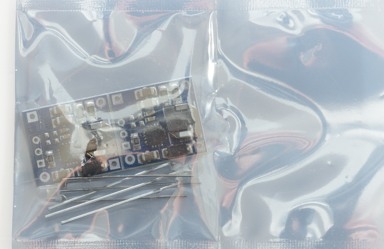
I got it in this bag without the led soldered in.


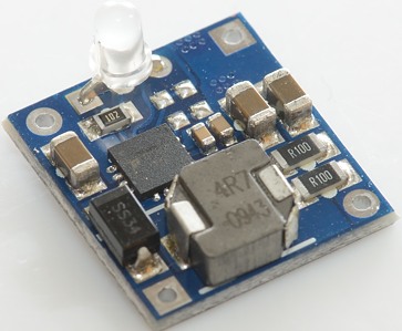
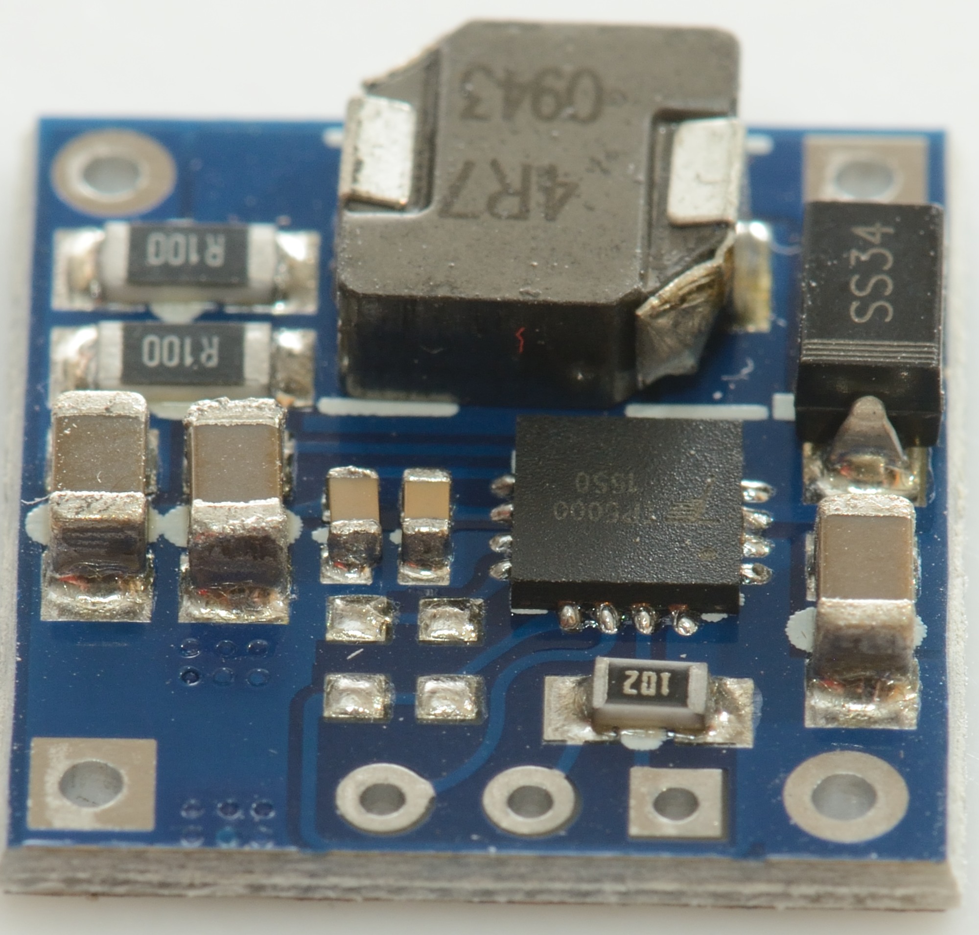
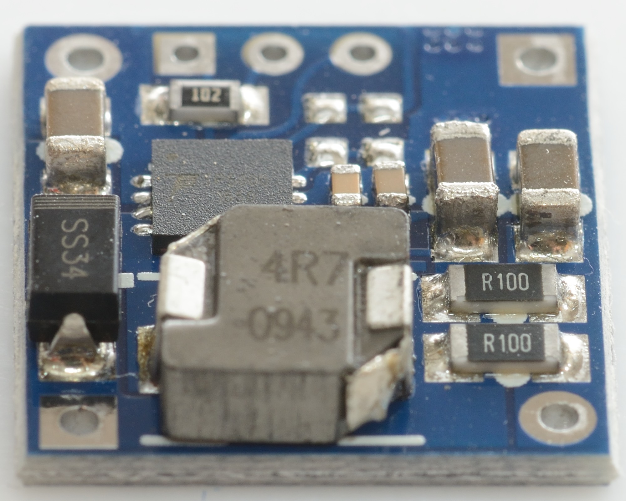
The regulator is a switcher with an inductor.


The supplied led is a 3 pin two color led that fits directly in the holes.
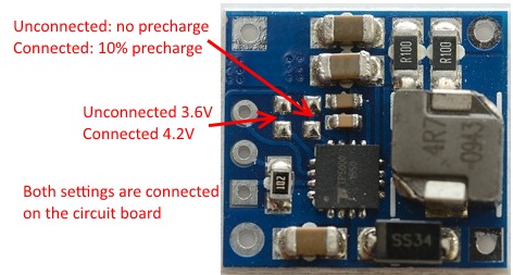
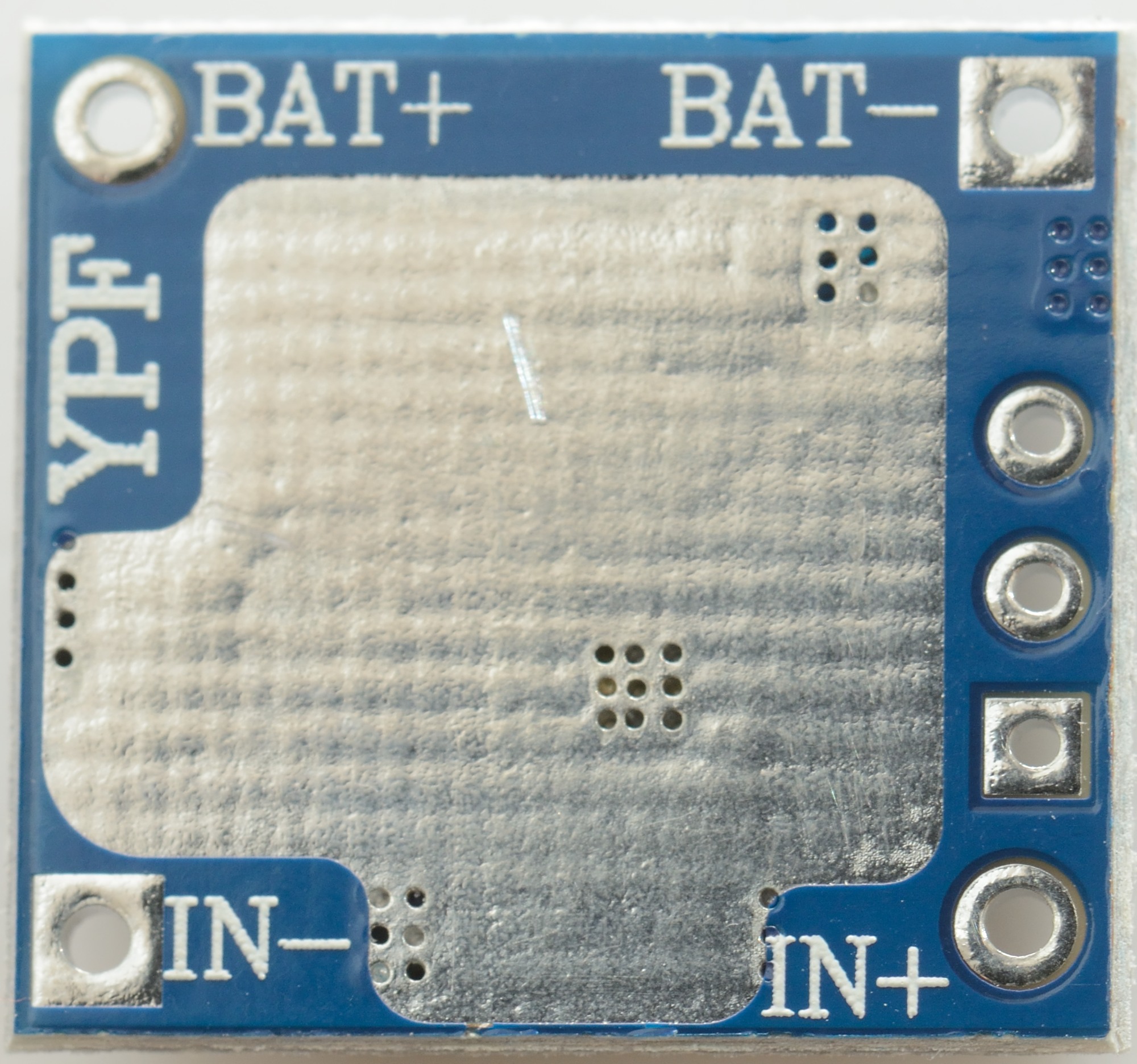
Default selection is 4.2 volt with 10% precharge current, to enable the other function a knife must be used to cut the trace between the two solder points.
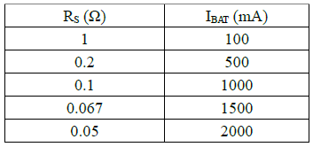
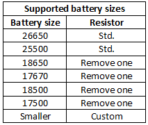
The charge current can be anything from 0.1A to 2A, this table shows some of the possibilities. Without a heatsink it is best to keep the current at 1A or lower.
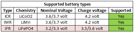
Charging LiFePO4 works, but is not ideal.
[size=+2]Measurements[/size]
[size=+1]Charging 4.2V LiIon[/size]
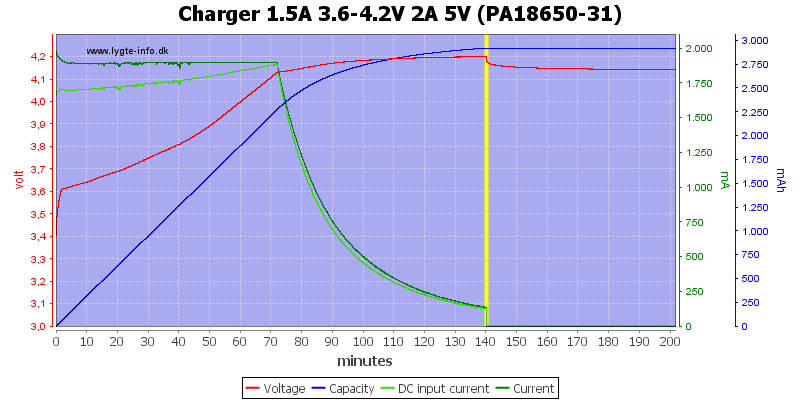
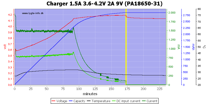
This looks like a very good CC/CV voltage charge curve with termination at 10% of charge current, here 200mA, the current is slightly below 2A due to heat.
Compared to linear regulators this regulator reduces current closer to 4.2V, this will make the charging a bit faster.
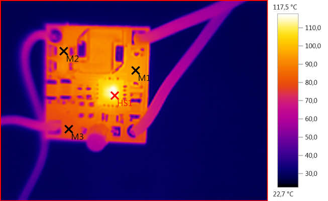
M1: 95,3°C, M2: 92,3°C, M3: 79,3°C, HS1: 117,5°C
The chip gets fairly hot and reduces the charge current.
With the higher input voltage the charge circuit could not maintain full charge current, it got too hot and regulated the current down.
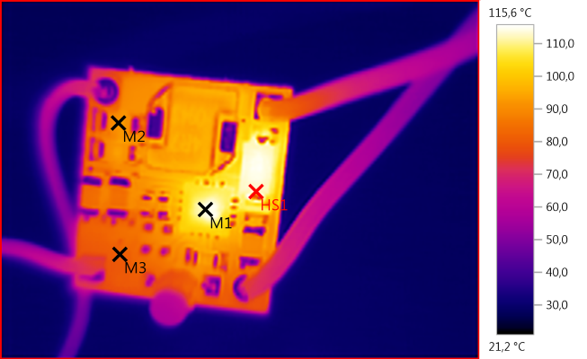
M1: 113,7°C, M2: 92,6°C, M3: 81,0°C, HS1: 115,6°C
With 9V input the diode gets very hot, this make the circuit board hotter and the chip has to reduce the current even more.
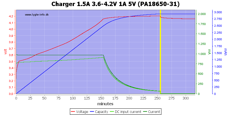
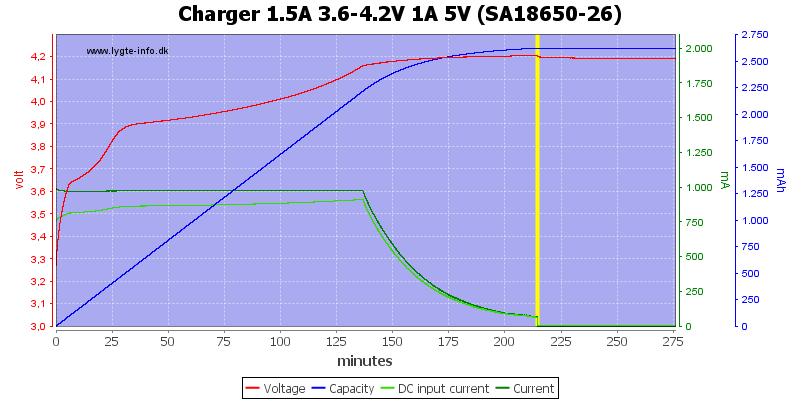
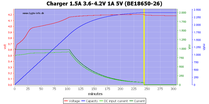
At 1A charging current the CC/CV voltage charge curve also looks fine.
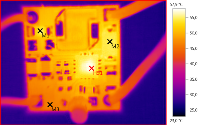
M1: 55,1°C, M2: 54,5°C, M3: 46,6°C, HS1: 57,9°C
1A current looks much more acceptable in temperature, nothing is really hot here (At least for electronic).

At 1A there is no heat problem with 9V input.
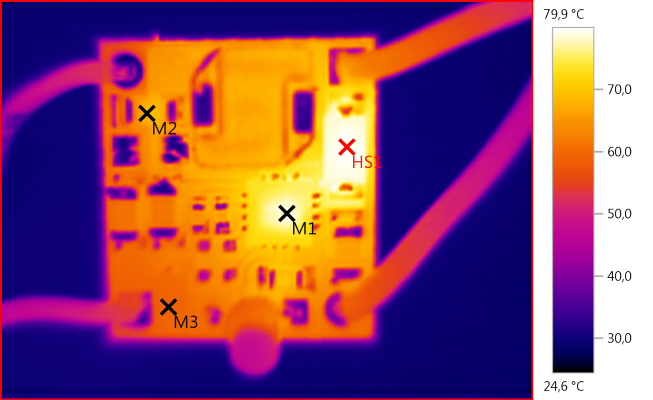
M1: 78,7°C, M2: 68,5°C, M3: 58,9°C, HS1: 79,9°C
With 9V input the diode gets warm again and increases the temperature of the chip, but it is still acceptable temperatures for electronic.
Both the new and old 2600mAh battery was charged perfectly.
Replacing the two 0.1ohm resistors with a single 1ohm resistor the current is down to 0.1A. I tested with a 14500 cell and it was charged perfectly to 4.2 volt, but with this low current ot took some time (0.1A is for smaller cells).
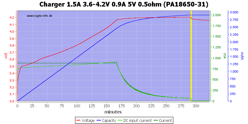
Simulating a long cable from a USB supply did not really affect the charger.
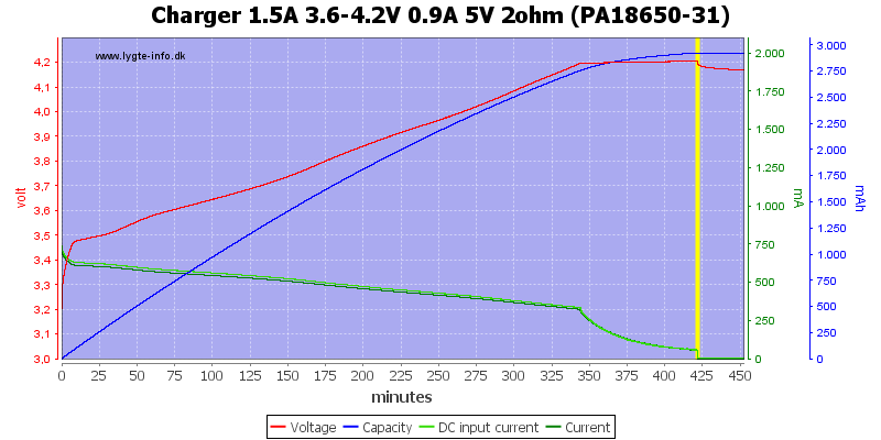
Adding more resistance between the 5V and the charger will slow down the charging, but the battery is filled.
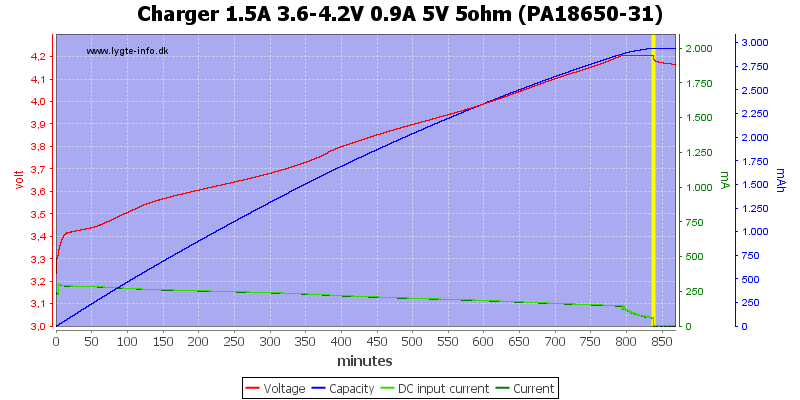
Even with 5 ohm in series it works, but very slowly
[size=+1]Charging 3.6V LiIon[/size]
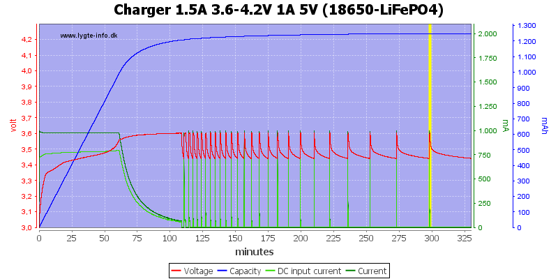
Breaking the 3.6 volt jumper I tried charging a LiFePO4 cell. The charge voltage is fine, but I do not like the automatic restart, it is placed at too high voltage.
[size=+2]Conclusion[/size]
It is a nice module for charging 4.2 volt LiIon batteries, even fairly small ones, the flexibilty in input voltage makes it useful for 6V unregulated solar panels.
I am not impressed with 2A performance, either a heatsink must be added or one of the resistors must be removed for best lifetime.
[size=+3]Notes[/size]
Here is an explanation on how I did the above charge curves: How do I test a charger
This is a charger module from ebay, it is based on the TP5000 charge controller, depending on settings it can either charge with 4.2 volt or 3.6 volt.
The official specifications from the ebay page is:
- Charge module- Switch mode charging.
- Current- 1.5A. changing the charging current by changing the Rprog resistor
- Charge precision- 1.5%.
- Input voltage- 4.5V-9V.
- Full charge voltage- 4.2V/3.6V.
- Led indicator- when soldered with LED
- Input interface- 4.5-9V.
- Work temperature- -10°C to +85°C.
- Inversed polarity protection - NO.
- Size- small to 17X18X5mm.
I got it from ebay dealer: wkws20
The above specifications are not completely correct, the module I got was configured for 2A charging.
I got it in this bag without the led soldered in.
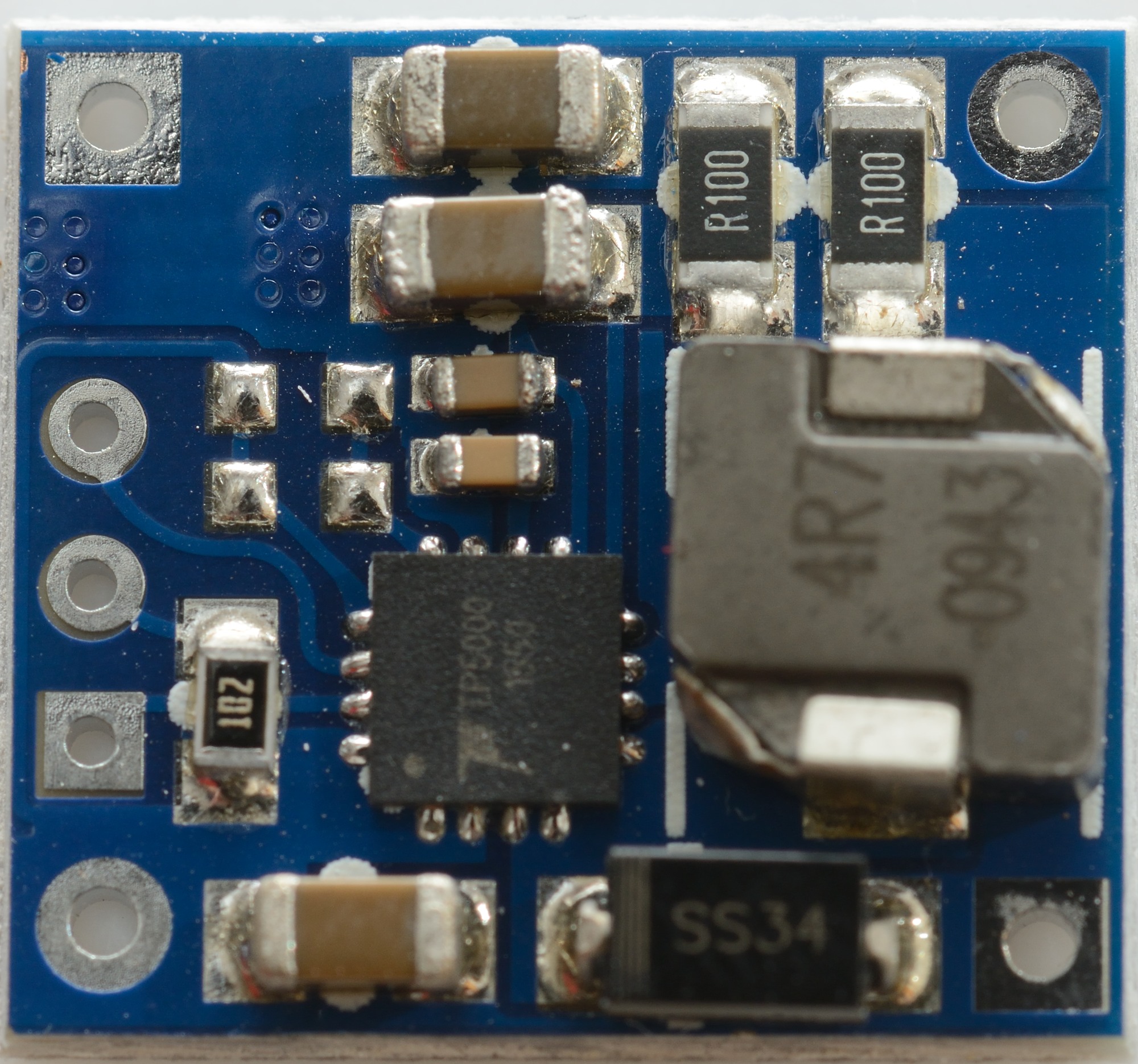
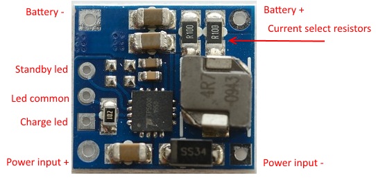
The regulator is a switcher with an inductor.
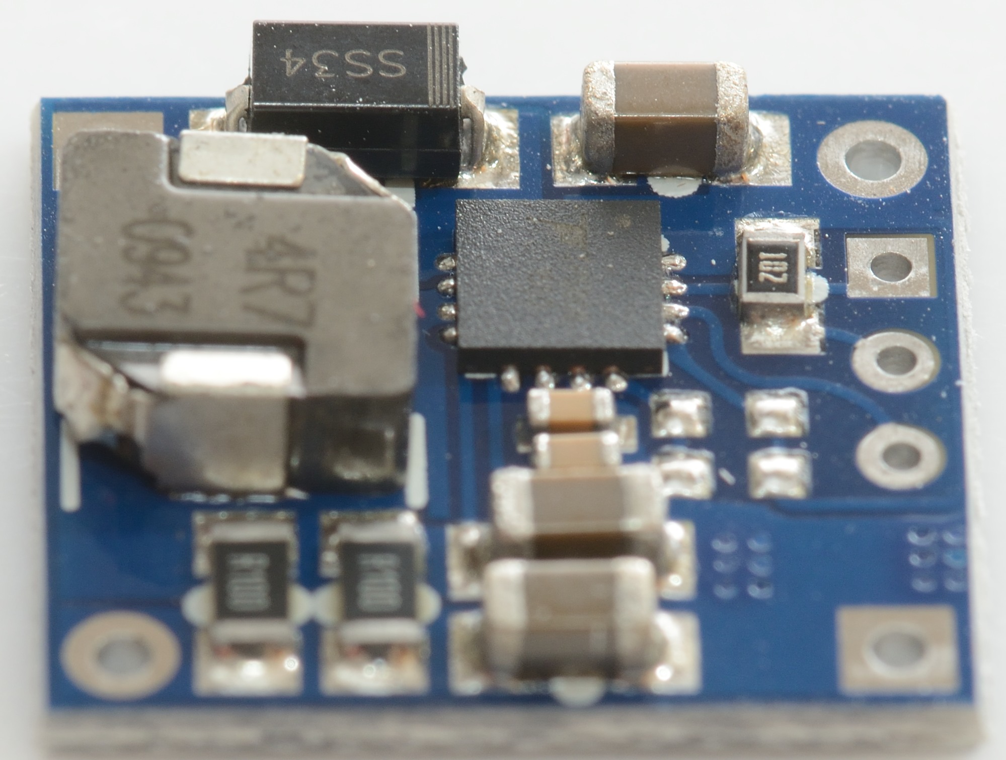

The supplied led is a 3 pin two color led that fits directly in the holes.
Default selection is 4.2 volt with 10% precharge current, to enable the other function a knife must be used to cut the trace between the two solder points.
The charge current can be anything from 0.1A to 2A, this table shows some of the possibilities. Without a heatsink it is best to keep the current at 1A or lower.
Charging LiFePO4 works, but is not ideal.
[size=+2]Measurements[/size]
- Power consumption when idle is 0.1 watt
- Discharge with 2uA when not connected to power.
- Discharge with 6uA when connected to power (5 volt supply).
- Will restart if battery voltage drops to 4 volt (4.2V setting).
- Will restart if battery voltage drops to 3.45 volt (3.6V setting).
- From 0 to 1 volt it will charge with 0.4A (1A setting).
- From 1 to 2.9 volt it will charge with 0.1A (4.2V/1A setting).
- From 1 to 2.4 volt it will charge with 0.1A (3.6V/1A setting).
[size=+1]Charging 4.2V LiIon[/size]
This looks like a very good CC/CV voltage charge curve with termination at 10% of charge current, here 200mA, the current is slightly below 2A due to heat.
Compared to linear regulators this regulator reduces current closer to 4.2V, this will make the charging a bit faster.
M1: 95,3°C, M2: 92,3°C, M3: 79,3°C, HS1: 117,5°C
The chip gets fairly hot and reduces the charge current.
With the higher input voltage the charge circuit could not maintain full charge current, it got too hot and regulated the current down.
M1: 113,7°C, M2: 92,6°C, M3: 81,0°C, HS1: 115,6°C
With 9V input the diode gets very hot, this make the circuit board hotter and the chip has to reduce the current even more.
At 1A charging current the CC/CV voltage charge curve also looks fine.
M1: 55,1°C, M2: 54,5°C, M3: 46,6°C, HS1: 57,9°C
1A current looks much more acceptable in temperature, nothing is really hot here (At least for electronic).
At 1A there is no heat problem with 9V input.
M1: 78,7°C, M2: 68,5°C, M3: 58,9°C, HS1: 79,9°C
With 9V input the diode gets warm again and increases the temperature of the chip, but it is still acceptable temperatures for electronic.
Both the new and old 2600mAh battery was charged perfectly.
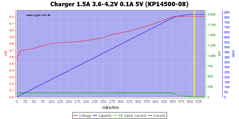
Replacing the two 0.1ohm resistors with a single 1ohm resistor the current is down to 0.1A. I tested with a 14500 cell and it was charged perfectly to 4.2 volt, but with this low current ot took some time (0.1A is for smaller cells).
Simulating a long cable from a USB supply did not really affect the charger.
Adding more resistance between the 5V and the charger will slow down the charging, but the battery is filled.
Even with 5 ohm in series it works, but very slowly
[size=+1]Charging 3.6V LiIon[/size]
Breaking the 3.6 volt jumper I tried charging a LiFePO4 cell. The charge voltage is fine, but I do not like the automatic restart, it is placed at too high voltage.
[size=+2]Conclusion[/size]
It is a nice module for charging 4.2 volt LiIon batteries, even fairly small ones, the flexibilty in input voltage makes it useful for 6V unregulated solar panels.
I am not impressed with 2A performance, either a heatsink must be added or one of the resistors must be removed for best lifetime.
[size=+3]Notes[/size]
Here is an explanation on how I did the above charge curves: How do I test a charger