HB2/H4 Glare Cup Question

hokiefyd

Newly Enlightened
Joined
Sep 11, 2012
Messages
125
I have owned two vehicles that take HB2 bulbs, a 2008 Honda CR-V and a 2009 Honda Ridgeline. The headlamp shape on these two vehicles is very different, but the reflector bowl design has similar elements. I think both CR-V and Ridgeline use housings from NAL (if that's even relevant), and both vehicles have factory-fitted housings.

In both vehicles, I've found that there is definitely a best left/right combination of housing and bulb...a "handedness" if you will. That is, one of the two bulbs produces a crisper cutoff in either the left or right housing than the other, and vice versa. I've never had the left and the right to be perfectly uniform (as the projectors in our MDX are), but putting one of the bulbs in the left housing and the other in the right, observing the results, and then swapping them and observing the results, I can designate one of the bulbs as working best in the left housing and the other as working best in the right housing.

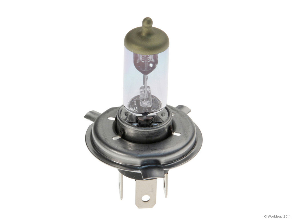
I say all that to ask this: how does the glare cup in the HB2 interact with the shape of the reflector bowl behind it? Not being a lighting engineer, I can only guess, but it seems to me that if you draw a straight line from the filament to either edge of that glare cup, and if you continue that line, it should intersect the reflector bowl at EXACTLY one of the fluted contours. As you look at the lamp from the front, and begin at the center, there is a nearly horizontal contour "edge" that extends from the center to your left (to the vehicle's right), and then also one that extends to your right (the vehicle's left) at a slightly downward angle (estimating 15 deg). This is for right hand traffic rule.

My guess is that all of the reflector bowl ABOVE those two "primary" fluted contours is used on low beam, the entire bowl is used on high beam (with the centered and un-shielded 60W filament), and the interaction between the glare cup and these two "primary" fluted contours is what produces the visible cutoff we see in the beam pattern. Do I have that approximately right? For that interaction to be maintained as perfectly as possible, and for multiple bulbs and housings to produce a uniform cutoff, both the bulb (filament and glare cup) and the housing bowl (fluted contours and the bulb mounting flange) would have to be manufactured to very tight tolerances -- that is probably stating the obvious.

What would/could explain the "handedness" I've observed in various bulb combinations -- why does one bulb seem to prefer one housing vs. the other? Is this more likely due to variations in the bulbs, or is it more likely due to variations in the housings themselves?

I thank you all in advance!

Jason
 

-Virgil-

Flashaholic
Joined
Mar 26, 2004
Messages
7,802
I have owned two vehicles that take HB2 bulbs, a 2008 Honda CR-V and a 2009 Honda Ridgeline. The headlamp shape on these two vehicles is very different, but the reflector bowl design has similar elements. I think both CR-V and Ridgeline use housings from NAL (if that's even relevant)

It's relevant in that one can frequently find common design elements in products of a given kind from a given maker. This has been the case for a very long time (Carello H4 headlamps, Cibie H4 headlamps, Marchal H4 headlamps, Hella H4 headlamps, Bosch H4 headlamps, etc, had characteristic design and construction features, regardless of size or shape, for example).

In both vehicles, I've found that there is definitely a best left/right combination of housing and bulb...a "handedness" if you will. That is, one of the two bulbs produces a crisper cutoff in either the left or right housing than the other, and vice versa.

As bulbs age, the filament deviates from its intended cylindrical shape and precise position, which changes the beam focus. Poor-quality or improperly-made bulbs start out with geometrical flaws and inconsistencies. This alone would easily explain why you see differences in the beam pattern when you swap bulbs. Other contributing factors could include one headlamp's bulb retainer holding the bulb firmly in position, while the other one allows a bit of movement or tends to **** the bulb on its seat. This is one of the disadvantages of the archaic H4 bulb: it's possible to design a very good bulb retainer and seat, and there are plenty of good ones, but it's also common, to have poor or very poor ones that let the bulb shift and rattle around or can be latched/secured with the bulb in a completely wrong position -- if you keep your eyes open in traffic, it won't be long before you see a vehicle with one or both headlamps lit up in a manner that makes it obvious the H4 bulb is rotated far out of its intended position, which also means it's crooked in the seat, but whoever installed the bulb was still able to secure the retainer and install the boot or cover.

Another possible contributing factor: the left and right headlamps on most vehicles with reflector-type lamps are not the same, because they're irregularly shaped to go along with the size and shape allotted by the vehicle designers for the headlamp package. So the part of the reflector that provides (for example) the hot spot for distance vision might be on the wide left side of the left headlamp, but it's on the narrow left side of the right headlamp. Optical engineers often do their best to make both headlamps' performance similar, but identical left/right performance is sometimes not possible, and it is not required by law.

putting one of the bulbs in the left housing and the other in the right, observing the results, and then swapping them and observing the results, I can designate one of the bulbs as working best in the left housing and the other as working best in the right housing.

That is an interesting observation. The practical outcome of it should be to buy a pair of these bulbs and repeat the experiment. The likely outcome is quite a bit less left/right variance, and the worst possible outcome, even if there's still significant difference, is that you'll see better at night.

how does the glare cup in the HB2 interact with the shape of the reflector bowl behind it? Not being a lighting engineer, I can only guess, but it seems to me that if you draw a straight line from the filament to either edge of that glare cup, and if you continue that line, it should intersect the reflector bowl at EXACTLY one of the fluted contours.

That's a reasonable assumption just going by appearance, but it is not necessarily correct. Where the shadow generated by the filament shield falls on the reflector (and/or where the projection of that shadow falls on the lens) is determined by the relative placement of the bulb, the reflector, and the optics in the reflector and/or lens. If an optical engineer is trying to make a headlamp with a razor-sharp cutoff and no upward light, there are techniques for doing that. In a reflector-optic lamp, these techniques include having the low beam optics (above the shadow) spaced slightly forward of the high beam optics (below the shadow), so that any small amount of light that happens to be below the shadow is directed downward by the corner and bottom surface of the spacer-step. But if the goal includes providing some uplight above the cutoff on low beam, then the opposite can be done: low beam optics spaced slightly aft of the high beam optics, so the small amount of light at the edge of the shadow is directed upward by the corner and top surface of the spacer-step. These kinds of corners and surfaces can also be placed elsewhere within reflector or lens optics, not just at the shadow line. You can see this in traffic, too; many HB2 headlamps present a generally low amount of light as viewed by a driver from the rearview mirror or the oncoming lane, except that each headlamp has a clearly visible bright spot or line. If you view such a headlamp from a distance, then come close enough to view the individual optical elements, you see that this bright spot is often created by a corner/top surface space-step or another upward-aimed optical element.

Sometimes there is no space-step between the low beam and high beam optics, but the geometry of the system is arranged so that the cutoff shadow falls slightly above or slightly below the apparent physical extent of the low beam optics in the reflector or lens. This is just another technique for adjusting cutoff sharpness, intensity in glare-controlled regions above horizontal, and uplight.

My guess is that all of the reflector bowl ABOVE those two "primary" fluted contours is used on low beam, the entire bowl is used on high beam

Correct.

both the bulb (filament and glare cup) and the housing bowl (fluted contours and the bulb mounting flange) would have to be manufactured to very tight tolerances

Yes, and even the geometrically tighter US HB2 spec (vs. the looser European/Asian H4 spec) is very loose relative to newer bulb designs.
 

hokiefyd

Newly Enlightened
Joined
Sep 11, 2012
Messages
125
if you keep your eyes open in traffic, it won't be long before you see a vehicle with one or both headlamps lit up in a manner that makes it obvious the H4 bulb is rotated far out of its intended position, which also means it's crooked in the seat, but whoever installed the bulb was still able to secure the retainer and install the boot or cover.

I have indeed seen this. It's immediately apparent that the wrong third (or so) of the reflector is shaded!

That is an interesting observation. The practical outcome of it should be to buy a pair of these bulbs and repeat the experiment. The likely outcome is quite a bit less left/right variance, and the worst possible outcome, even if there's still significant difference, is that you'll see better at night.

I'll check again; I'm pretty sure I have either those or the Vision Plus in addition to the OEM bulbs (I've used so many over the years). I know I have used the older Xtreme Power bulbs from Philips.

Note also that I know that the performance of the lamp isn't defined by its cutoff, but I'm obsessively compulsive (or compulsively obsessive!) when it comes to stuff like this -- I'm an avid observer of lamp cutoff. Not because I think it makes for a good or bad lamp, but because I just enjoy looking at the different cutoff shapes employed by different manufacturers, and wonder about all the different design requirements that resulted in the production lamp.

If an optical engineer is trying to make a headlamp with a razor-sharp cutoff and no upward light, there are techniques for doing that...

That's very interesting -- thank you for elaborating on that.

Sometimes there is no space-step between the low beam and high beam optics, but the geometry of the system is arranged so that the cutoff shadow falls slightly above or slightly below the apparent physical extent of the low beam optics in the reflector or lens. This is just another technique for adjusting cutoff sharpness, intensity in glare-controlled regions above horizontal, and uplight.

I would say that this describes the CR-V's and Ridgeline's lamps well. There is that stepped "line" on the reflector bowl, but there's not a dramatic change in the depth of the bowl either above or below that line. I imagine this also influences how different the low and high beams are from each other. I imagine a very crisp distinction in the reflector bowl might produce a very defined cutoff, but perhaps at the expense of a compromised high beam pattern. And maybe a rather "flush" transition in the reflector bowl might produce a less distinct cutoff, but perhaps with the reward of a more uniform high beam pattern? Even if I'm wrong, there, I can certainly see that you can't have it all in a single bulb housing like this.

One other question about these bulbs, if I may. Looking at the bulb straight on, the vertical axis of the filament mounting is slightly off from the "top" alignment lug on the base. You can sort of see that in this picture, despite it being one of those nasty blue-coated bulbs. The filament axis is about 5 deg off from being directly in line with the top lug. Do you know why that is? Does that have something to do with the H4 originally being designed in Europe, where they often have an angled cutoff to either the right or the left of center? Does slightly clocking the filament and glare cup relative to straight up and down vertical help accomplish this?

Y9003.jpg
 

-Virgil-

Flashaholic
Joined
Mar 26, 2004
Messages
7,802
I have indeed seen this. It's immediately apparent that the wrong third (or so) of the reflector is shaded!

Minor point, but since you're trying to learn about H4 headlamps: if the bulb is at the center of a reflector of uniform shape, the low beam filament shield creates a shadow arc of 165 degrees. That is 180 minus the 15-degree included angle of the edges of the cutoff shield. The bulb may be located below the axis of the reflector so as to enlarge the low beam area, increasing the amount of light in the low beam.

Note also that I know that the performance of the lamp isn't defined by its cutoff, but I'm obsessively compulsive (or compulsively obsessive!) when it comes to stuff like this -- I'm an avid observer of lamp cutoff. Not because I think it makes for a good or bad lamp, but because I just enjoy looking at the different cutoff shapes employed by different manufacturers

I can certainly understand that. :) There is some very old, foundational literature on the design of the filament shield. I couldn't conveniently lay hands on my copies, but you might ping Daniel Stern and see if he has it in accessible form.

I imagine a very crisp distinction in the reflector bowl might produce a very defined cutoff, but perhaps at the expense of a compromised high beam pattern. And maybe a rather "flush" transition in the reflector bowl might produce a less distinct cutoff, but perhaps with the reward of a more uniform high beam pattern?

Not so much, no. Keep in mind that while it's true the H4 has a large efficiency deficit on low beam because only about 55% of the total reflector area can be used to collect and magnify light for the low beam, the flip side of that is that there's an area of the reflector/lens dedicated for the high beam. So it's much more feasible to tune and optimize both beams than it is with bulbs like HB1 (9004), HB5 (9007), and H13 where the whole reflector/lens area is used for both beams, therefore the whole reflector/lens must be compromised to do two jobs acceptably rather than one job well.

Looking at the bulb straight on, the vertical axis of the filament mounting is slightly off from the "top" alignment lug on the base.

If I understand you correctly, you're noticing that the filament shield is not symmetrically clocked with respect to the top alignment lug on the base. That is true. This was a more or less arbitrary decision made a very long time ago (early 1950s) when the asymmetrical cutoff was being developed with the incandescent predecessors of the H4 bulb.

The entire bulb gets clocked in whatever position goes along with the optics of the lamp. Generally (plus or minus a degree or two for optical tuning) if the top lug and top/horizontal terminal are straight up, the filament shield is positioned so its starboard edge casts a horizontal shadow and its port edge casts a shadow angling 15 degrees down. If you take two basic H4 headlamps of the same size, shape, and manufacturer, with optically-patterned lenses and ordinary parabolic reflectors, one for left-hand traffic and one for right-hand traffic, and you put them on a table rightside-up with the lenses away from you, you will see that the bulb in the left-traffic lamp is clocked noticeably clockwise (15 degrees, as it happens!) relative to the position of the bulb in the right-traffic lamp. If you look at a symmetrical-beam motorcycle headlamp of that same basic technology, you'll see the bulb is clocked so the filament shield is symmetrical. But this doesn't necessarily hold in all cases. The Cibie Z-beam and BOBI H4 headlamps used basic parabolic reflector and optical lens, but its bulb clocking was rotated clockwise for a right-traffic pattern and vice versa. And now that we are no longer limited to parabolic reflectors (we have segmented/freeform/complex reflectors like the ones on your vehicles) there's considerably more freedom in bulb clocking, which can be advantageous in dealing with odd-sized reflectors .
 

hokiefyd

Newly Enlightened
Joined
Sep 11, 2012
Messages
125
If I understand you correctly, you're noticing that the filament shield is not symmetrically clocked with respect to the top alignment lug on the base.

Indirectly, yes. I was noticing the vertical axis of the filaments within the glass envelope as they are clocked in the 3-tab metal base of the bulb, but yes, I see now that that means the filament shield is also clocked with respect to that top tab. If a vertically clocked top tab means the left side of the filament shield is 15 degrees below level, am I correct in guessing that a symmetrical lamp (to use your motorcycle example) clocks that top tab 7.5 degrees clockwise as you look at the back of the lamp, to position that filament shield exactly horizontal in the housing?

I'm somewhat certain that both of my Honda lamps clock the bulb with the top tab at the 12:00 position. It had been my guess that the left lower edge of the filament shield (now I know it's 15 deg lower) creates the step up in the cutoff on the right side of the beam pattern -- that additional light being cast onto the left side of the reflector, which would (I presume) cast it back to the right side of center in the beam.

Lamp optics truly fascinate me. I've wanted to somehow model different reflector bowls at home to be able to experiment with how different positioning of a lamp within them creates different optical effects, and how different contours of the bowl itself does the same. Unfortunately, I've never really been able to think of a way to create those surfaces by hand without a WHOLE LOT of trial and error. I guess the concept of the free-form reflector, or at least its widespread use, was really enabled by computer-based design. I used to think that ANY HB2/H4 housing would produce that characteristic 15 degree upsweep in the cutoff, due to that shield. Maybe that's more true in a parabolic reflector. It's clear that all reflectors don't necessarily create that pattern, though. It's fascinating to me how they can get nearly identical-looking cutoff patterns with completely different bulb types and reflector shapes. Hondas typically have this step up on the right side, and Civics and Odysseys do it with HB4s and CR-Vs and Pilots and Ridgelines do it with HB2s...really neat to me.
 

jaycee88

Newly Enlightened
Joined
Jan 13, 2015
Messages
175
. If a vertically clocked top tab means the left side of the filament shield is 15 degrees below level, am I correct in guessing that a symmetrical lamp (to use your motorcycle example) clocks that top tab 7.5 degrees clockwise as you look at the back of the lamp, to position that filament shield exactly horizontal in the housing?

Yes, although for it to be horizontal I believe it would be clocked 15 degrees clockwise as you look at the back of the lamp.

Example
 
Last edited by a moderator:

-Virgil-

Flashaholic
Joined
Mar 26, 2004
Messages
7,802
Indirectly, yes. I was noticing the vertical axis of the filaments within the glass envelope as they are clocked in the 3-tab metal base of the bulb, but yes, I see now that that means the filament shield is also clocked with respect to that top tab.

You should download ECE Regulation 37, which contains the detailed specifications for car bulbs, including dimensional and orientational drawings. If you want to compare the H4 spec to the US HB2 spec, the HB2 spec is here. Daniel Stern wrote up a big in-depth analysis of the difference some years ago; I don't see it on his site, but maybe he'd send it to you for the asking.

If a vertically clocked top tab means the left side of the filament shield is 15 degrees below level, am I correct in guessing that a symmetrical lamp (to use your motorcycle example) clocks that top tab 7.5 degrees clockwise as you look at the back of the lamp, to position that filament shield exactly horizontal in the housing?

Yes.

guess that the left lower edge of the filament shield (now I know it's 15 deg lower) creates the step up in the cutoff on the right side of the beam pattern

Correct.

Lamp optics truly fascinate me. I've wanted to somehow model different reflector bowls at home to be able to experiment with how different positioning of a lamp within them creates different optical effects, and how different contours of the bowl itself does the same.

There are computer simulation tools for exactly that kind of thing. ReflectorCAD, SPEOS, and others.

I guess the concept of the free-form reflector, or at least its widespread use, was really enabled by computer-based design.

That's right.

I used to think that ANY HB2/H4 housing would produce that characteristic 15 degree upsweep in the cutoff, due to that shield. Maybe that's more true in a parabolic reflector.

Not even then, actually. It depends on the profile of the parabolic reflector. The Z-beam headlamps had parabolic reflectors, and so did the BOBI headlamps, and they did not produce that 15-degree upsweep.

It's fascinating to me how they can get nearly identical-looking cutoff patterns with completely different bulb types and reflector shapes. Hondas typically have this step up on the right side, and Civics and Odysseys do it with HB4s and CR-Vs and Pilots and Ridgelines do it with HB2s...really neat to me.

That horizontal-and-ramp ___/ shaped cutoff is easy to achieve with an H4 bulb. It can be achieved easily but inefficiently with many single-filament bulbs such as H1 or HB4, just by putting an external shield below the bulb to cast that same 165-degree-arc shadow on the bottom area of the reflector, but we don't do it that way any more because now with complex optics we can "look at" the edge of the filament and the dark space immediately adjacent to it, and project those edge images to create a cutoff of whatever shape we want. That's why the new H19 bulb (discussed here) has a low beam filament shield that is symmetrical and located well below the longitudinal axis of the low beam filament: it's used to reserve a portion of the reflector exclusively for high beam; the filament-edge images are used to create the low beam cutoff, and the efficiency advantage over H4 comes because a larger portion of the reflector is available for low beam.

You will certainly get more than your money's worth buying the following SAE papers:
-870059
-730279
-840041
-870060
-870064.

Also, peruse (for free) these patents:
-Ducellier Z-beam number 1
-Ducellier Z-beam number 2
-Bosch Z-beam
-Cibie Z-beam number 1
-Lucas Z-beam number 1
-Cibie Z-beam number 2
-Lucas Z-beam number 2
-Cibie complex reflector number 2
-Cibie complex reflector number 1
-General Electric faceted reflector
-Lucas homofocal reflector
-Philips H4 bulb
 
Last edited:

-Virgil-

Flashaholic
Joined
Mar 26, 2004
Messages
7,802
Yes, although for it to be horizontal I believe it would be clocked 15 degrees clockwise

No, that would mean a horizontal cutoff line on the right side of the beam and an upsweep to the left, that is a left-traffic headlamp. 7.5 degrees is the correct figure for "straight up"/symmetrical.
 

hokiefyd

Newly Enlightened
Joined
Sep 11, 2012
Messages
125
You should download ECE Regulation 37, which contains the detailed specifications for car bulbs, including dimensional and orientational drawings...

I thank you kindly for all the resources you linked in this post. I'll certainly bookmark this thread for further reading!

Cheers!
 

hokiefyd

Newly Enlightened
Joined
Sep 11, 2012
Messages
125
https://www.youtube.com/watch?v=QvY-SnhjXOQ

I just watched this video put on by ReflectorCAD, and learned a ton from it. I didn't know that the inner-most segments commonly contribute to the outer-most portion of the beam (and opposite for the outer-most segments). The bit about segment filler shadowing to reduce glare is also fascinating to me. The Ridgeline's headlamps produce about 6-8 strong vertical streaks of light to the immediate sides of the vehicle -- I wonder if that's due to something like they showed in the video -- segment fillers not being shadowed.

How cool. I'd love to get my hands on that software -- I'd geek out for days, drawing up notional lamp designs!
 
Top