On the topic of "how do I heatsink my zener diode?", the datasheet does say that the "primary path of (thermal) conduction is through the cathode lead".
This is on page 4 of the datasheet for the 1N53xx 5 watt zener diode. Figure 1 shows the thermal resistance as the length of the zener's leads changes. It assumes that the leads are soldered to something that is a heatsink or closely coupled to a heatsink.
This info is from the OnSemi version of the datasheet. Their website is onsemi.com, and a search for 1N5333 will usually bring up the datasheet, but seems to be broken right now.
Digikey has this link to the datasheet:
http://www.onsemi.com/pub/Collateral/1N5333B-D.PDF
Anyway... copper-clad circuit board is how I usually build boards. I would recommend having the diode's cathode (the end with the stripe) soldered to a large area of copper, and then using a thin insulating layer to couple it to a heatsink. The heatsink could be the interior of an aluminum housing.
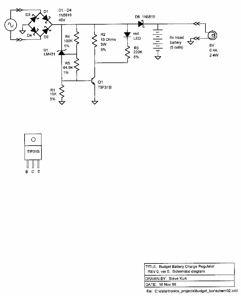
Many years ago, I threw together a quick shunt regulator to allow a friend to charge nicads while touring. It's more precise because it set the battery charging voltage. The arrangement is basically that a voltage reference is used a zener diode, and then that voltage is fed into a NPN transistor's base. The collector is connected to the voltage to be regulated, and the emitter is grounded. The transistor is just acting as a current amplifier for the zener.
My circuit does add a power resistor in series with the transistor's collector, just so the resistor can help get rid of some of the heat.
The voltage reference could be replaced with a low-power zener, if it is just being used to limit the input voltage to series regulator like the MIC2940.
Here's my schematic...
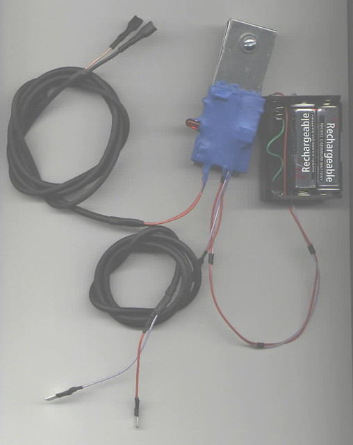
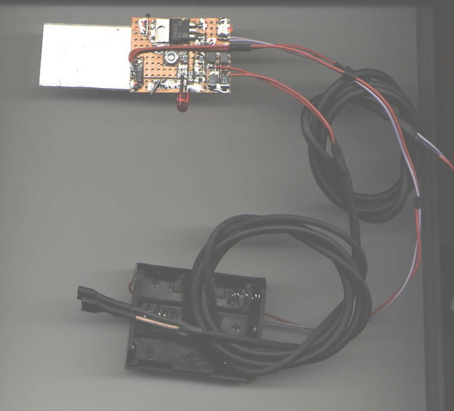
and a few photos of the board...
In these photos, the transistor has it's tab soldered to the copper-clad board, and a piece of aluminum is bolted to the back of the board. I think I had the power resistor epoxied to the other side of the aluminum. The whole thing is coated with plasti-dip, which is a small step up from just wrapping it in tape, but it does provide some protection from moisture.
The aluminum needs to be exposed to airflow.
So.. in summary, connecting the leads of the zener to a large thermally conductive body is the best way to get heat out of it. Attaching a heatsink to the body of the zener is not as good since the zener's body is not thermally conductive. It's still better than no heatsinking at all, though.
In my circuit, I used a transistor and power resistor to dissipate the heat, and the transistor had a package designed to get the heat out.
There are better ways to do it, but for a quick cheap design, this isn't so bad.
")
Always check on how hot the zener gets once you do build it up and test it. If it is too hot to touch, then it's probably above 60C, and could use a bit more heatsinking. If it burns you, then it's definitely in need of more heatsinking!