Class 2: The ArcLuxAAA

pbarrette

Enlightened
Joined
May 5, 2004
Messages
346
Location
Huntsville, AL
Hi all,

Here is my first Luxeon based Mod, completed only yesterday:
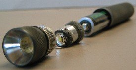
The ArcLuxAAA:
ExplodedB.jpg

ExplodedA.jpg


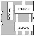
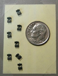
The power behind this light comes from the well known Zetex ZXSC300 circuit which has been hand soldered by myself. I use a circuit layout which allows me to ditch the PCB entirely and solder the components directly to each other. This gives me a much smaller circuit size since I can also work in 3 dimensions.

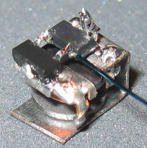
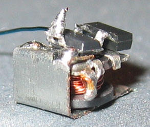
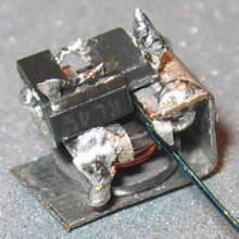
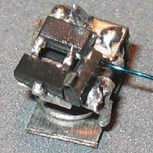
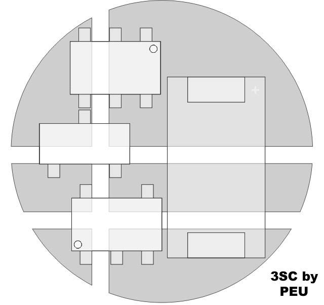
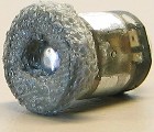
Here's a picture of the basic circuit before the schottkey diode and output capacitor have been added:
ZxInductorAdded.jpg


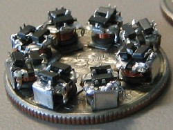
The addition of the diode and capacitor add an additional 2-3mm of height to the circuit, though I forgot to take a picture of that stage of construction.

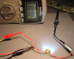
This circuit outputs 150mA from a fresh AAA alkaline and 147mA from a NiMH to drive a 1W PWAJ binned Luxeon HD emitter. I would have used a better bin, but that's all I've got folks.

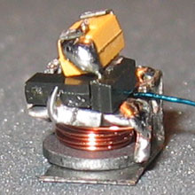
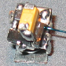
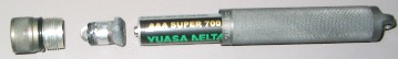
I have been working on a Solitaire based Lux mod where space for the pill is at a premium. The ArcAAA head, on the other hand, is positively roomy in comparison, and the on/off switching is much more simple to work with. This allowed me to add a small heatsink to my pill to help keep the Luxeon bright and safe.
PillAnode.jpg
PillCathode.jpg
PillHeadOn.jpg
PillTail.jpg


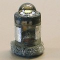
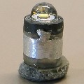
The heatsink is formed from an aluminum tube which is slotted along the length and has two tabs at one end. The slot allows me to both fit the tube over the circuit and adjust the diameter to provide solid contact with the light head. The tabs are bent inwards to make contact with the Luxeon's heatsinking lug on the bottom of the LED.

With the addition of the heatsinking, I could probably get away with using 2 1/2-AAA's which would give me ~350mA through the Luxeon. I don't have any of those batteries yet, so I am unable to test the heatsinking ability at that current. I can say that the head itself gets extremely warm at 350mA, but when the body is attached to the head there should be some decent thermal transfer to the body as well.

As it stands, the heatsink performs wonderfully with the default 150mA draw from 1xAAA. The light warms up a little, but stabilizes at ~5mins with a temperature that is well within the comfort range of bare skin.

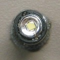
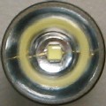
Drilling the reflector of the ArcAAA's head, I found that the stock reflector does, in fact, collimate the light output somewhat. A good indication of this fact is that a decent portion of the yellow phosphor is visible in the reflector when looking at the light head on:
ReflectorOff.jpg


Also, the reflection is nicely visible in this heavily underexposed shot with the light on:
ReflectorOn.jpg


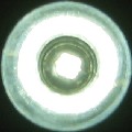
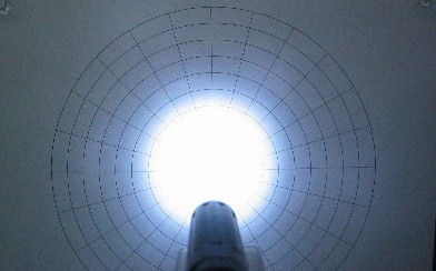
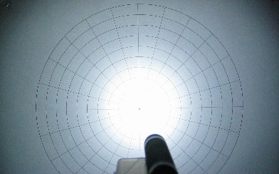
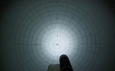
This produces a small hotspot with a lot of sidespill, which is clearly visible in the beamshots.

And, what flashlight mod would be complete without beamshots?

So here you are:

The target with ambient light at Exposure setting #1:
Target-Exp1.jpg


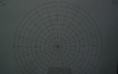
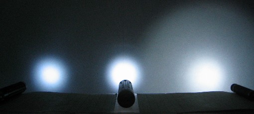
The lights are, in order from left to right:
Xnova 3LED 1xAAA
Xnova 5LED 1xAA
ArcLuxAAA
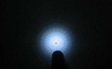
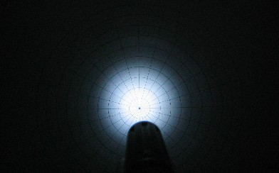
At Exposure setting #1 (Exposure set from ambient light):
XnovaAAA-Exp1.jpg

XnovaAA-Exp1.jpg

ArcMod-Exp1.jpg


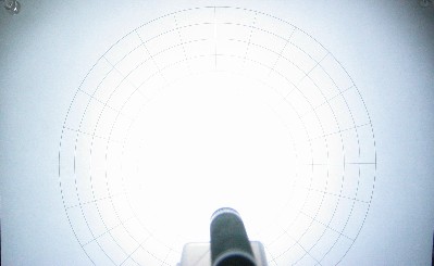
At Exposure setting #2 (Exposure set from Xnova AAA):
XnovaAAA-Exp2.jpg

XnovaAA-Exp2.jpg

ArcMod-Exp2.jpg


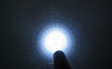
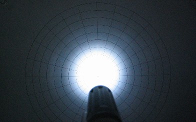
At Exposure setting #3 (Exposure set from ArcLuxAAA):
XnovaAAA-Exp3.jpg

XnovaAA-Exp3.jpg

ArcMod-Exp3.jpg


Now here they are lined up next to each other:
ArcMod-Compare.jpg


Thanks for having a look,
pb
 

pbarrette

Enlightened
Joined
May 5, 2004
Messages
346
Location
Huntsville, AL
Hi PEU,

I don't have any larger pics right now. I'll take some when I get home tonight and post them up.

Basically, I lined up pins 1 & 2 on the transistor with pins 4 & 5 on the IC, then soldered them directly to each other. If the components are dead-bugged (upside down) it makes it much easier to do this. It's also easier if the components are fixed in place, like lying on a piece of tape. I used the sticky part of a post-it note to hold them still while I soldered.

I then bent IC-pin 1 and Transistor-pin 3 downwards. In this configuration, the Trans/IC combo sits deadbug on top of the inductor (which is also upside down). IC-pin-1 sits nicely on one of the inductor pads while Trans-pin-3 sits nicely on the other. These are then soldered in place with the Trans/IC pair shifted a bit off center.

With the tran/IC pair off center, you have space to add the shottkey on top of the inductor as well. The anode of the shottkey is soldered to the same inductor pad as Trans-pin-3.

Here's an idea of the layout from a top view:
ZetexLayout.jpg


The sense resistor can be laid across the top of the Zextex if you have SMT resistors, or you can use a sense wire and solder that in. I twisted the sense wire loop to reduce current induction into it, then wrapped it around the inductor coil. I'm probably loosing a bit of efficiency there, but I can't measure any losses on my meter.

From there, one end of the cap is soldered to IC pins 2 & 3, and the other end of the cap is soldered to the cathode of the diode (Which should be sticking straight up in the air).

Now the circuit is done and you just add the LED in parallel with the cap.

Hope this helps. I'll post some more detailed pics of the circuit layout later.

pb
 

pbarrette

Enlightened
Joined
May 5, 2004
Messages
346
Location
Huntsville, AL
Hi Cy,

I'm really doing this as a hobby, but I do have a lot of leftover Zetex IC's and transistors left over from my purchase of 20 off digikey.

I certainly can't do a full production run of these since the circuit must be carefully hand assembled, but I would definitely consider making a few extras if people are interested.

Send me a PM if you want one and we can likely work something out.

pb
 

PEU

Flashlight Enthusiast
Joined
Feb 26, 2004
Messages
3,600
Location
Buenos Aires / Argentina (I like ribs)
thanks for the explanation peter, I'll try again tomorrow, but 1st I'll look for a decent very small plier I'm needing for the job. I really apreciate your help.

which value did u used for the sense?

Pablo
 

pbarrette

Enlightened
Joined
May 5, 2004
Messages
346
Location
Huntsville, AL
Hi PEU,

As promised, the pictoral circuit construction guide.

First step, solder the IC/Transistor together (old pic):
ZxPreSolder.jpg


Then, solder that to the inductor pads and solder the first end of the current sense resistor wire:
BarePos.jpg
BareGnd.jpg


Now we add the schottky diode. I'm using an SOT-23 shottky diode pair for this one. I just cut off the pin that leads to the second diode in the package. Why you ask? Because I scrounged it out of an old memory card that cost me $.10 and has 28 of these things on it. A lot cheaper than shottkys from digikey. This one has a Vf of .232v, so I can't complain there either.
DiSide.jpg
DiTop.jpg


Now that we have that done, we add the capacitor. This is a 33uF Kemet tantalum scrounged from a dead cell phone. Now that I look at the pics, I realize that I should have soldered this one on its side. That would have brought the height down about .5mm more. On the ArcLuxAAA, I also added an 0805 sized 4uF ceramic cap which sat right next to the tantalum.
DiCapPos.jpg
DiCapTopPos.jpg


Now, the other end of our sense resistor wire is soldered to ground and we check the output through our test Lux:
CurrentCheck.jpg


Whoops.. Only 107mA. Looks like I'm going to have to trim that wire down a bit. Just desolder, trim, resolder until the output gets where you want it. (Also, note the PCB from a dead cell phone in the background. Nice little capacitors there.)

I haven't been able to push any more than 153mA out of this circuit using 1.5v yet and that's getting lucky. Part of this has to do with the fact that I'm using 22uH inductors that I had on hand instead of the recommended 100uH ones. Also I'm sure, is the fact that I could probably use a higher output cap, possibly an input cap, and most likely some better diodes would help as well.

Even then, this circuit is pretty close to maxed out and would probably give only another 5mA or so IMO. Now, hooking that same circuit with the 107mA output up to 2x(slightly used)AAA's gives us 250mA. With 2xAA's (fresh out the box): 295mA. This is because the current output of the Zetex is directly linked with the supply voltage, with better efficiency in the 3v supply range than in the 1.5v range.

So, to answer your last question: I have no idea what the actual resistance value of the sense wire is. My meter doesn't measure low enough to get a valid reading from this wire. I start out with ~6cm of ~30ga. enameled wire and start cutting it down from there. It's best to start out longer, then start cutting it down. I start fairly short since I'm using the same wire and have built a number of these circuits now.

Just remember, if you cut the wire too short, the transistor won't switch and the LED will not light. So if you are close to the max, shorten the wire, and now the circuit won't light.. It's because the wire is now too short and you'll have to start over. At least you can now use the "too short" wire as a guide.

Hope this helps,
pb
 

pbarrette

Enlightened
Joined
May 5, 2004
Messages
346
Location
Huntsville, AL
Hi PEU,

Good luck. Personally, I find that the sense wire is one of the hardest parts to solder in this circuit. I now always tin the ends of the wire before I try to solder them on. If I don't, I get a cold joint and the wire eventually comes loose. I usually give the wire a firm tug after soldering to make sure that it really is a solid joint.

Also, you should be able to see from the pics that I bent a thin strip of aluminum around the inductor. This strip starts out covering the IC-pin-1 side of the inductor pad, bends down the side of the inductor, then bends parallel to the "bottom" of the inductor. I solder that in place on the inductor, then I add the transistor/IC pair. I find that this makes it easier to attach the positive power supply later. I originally started doing this in my Solitaire 5mm mods and used the bottom tab directly as the positive battery contact.

------------------

Now.. To everyone that has PM'ed me about buying one of these..

I was originally telling cy to PM me on this since he gave me a deal on the ArcAAA body and empty head that I used in this project.

I didn't expect the number of PM's I have received and I frankly don't quite know what to do. I would hate to say no to any of you, but I really haven't thought about pricing on this yet, and I'm not quite sure where to start. The drawback of my circuit design's lack of a PCB is that the circuit can't just be fabbed out somewhere, they are all built by hand and that takes time. Also, the Luxeon emitter must be cut into as well. I had to cut into the plastic casing under the leads to allow the leads to be bent downwards so they don't stick out from the side of the emitter. The emitter is actually larger in diameter than my circuit, and if the positive lead was sticking out from the side, it might short out the lux. I then have to cut out the cathode side as well to make sure that I can center the emitter properly.

I have a lot of things happening in my life currently (mainly, a pending move from Iowa to Germany) that make it difficult to produce more than a few of these right now. Also, after a quick parts count, I find that I only have the components to make ~7 circuits right now and I only have 2 HD emitters left.

So, thank you for the interest, but I really can't do more than 2 complete pills right now simply due to lack of Lux's. I could make 5 more circuits after that, but the cutting, fitting, soldering, heatsinking, potting is a pretty delicate operation and I wouldn't consider it as a kit for the inexperienced.

Finally, since this is a brand new mod for me I want to abuse the light for a while before I sell any of these as a drop-in replacement. I don't want to ship one out only to have it die on someone within a month. I'm currently not entirely satisfied with the heatsink either, so I'll be working on perfecting that in about a week when I get my new lathe.

Thanks again for the interest,
pb
 

PEU

Flashlight Enthusiast
Joined
Feb 26, 2004
Messages
3,600
Location
Buenos Aires / Argentina (I like ribs)
Hi, I'm frustrated to the max, because I can't build the circuit "in the air" as you explained, so I just finished a new pcb design for the zetex (to be accurate, redrawing what a friend of mine did).

I call it the 3SC (3 straight cuts) on monday I'll build it and post some pics

Here is the layout, the diameter is 10mm

zetexpeu.jpg


inductor goes on the other side

Pablo
 

pbarrette

Enlightened
Joined
May 5, 2004
Messages
346
Location
Huntsville, AL
Hi all,

Thanks GreenLed!

PEU: I didn't see your last post until just now.. I need to subscribe to this thread.. /ubbthreads/images/graemlins/smile.gif

It takes a bit of a fine touch with the soldering iron to get the 3D circuit together. I find that it's best to build the circuit in this order:

1) Solder the IC and transistor together.
2) Solder the pair to the inductor.
3) Attach one end of the long sense resistor wire.
4) Add the diode at the transistor output.
5) Stack the capacitor on top of the IC/transistor pair.
6) Attach other end of sense resistor and test output.

For step 1, I lay the IC and transistor next to each other, pin to pin, in the deadbug (upside down) position. It helps to lay them out on a piece of tape, or (seen in pic above) on the sticky part of a post-it note. I then use a clean soldering iron tip, melt some solder on it, then apply the tip to the first joint. The solder on the tip flows to the joint and makes the connection. Repeat for joint #2.

With step 2, I keep the newly soldered pair on the tape. I then use a small, flatblade, jewelers screwdriver to bend IC pin 1 and transistor pin 3 down until it is touching the tape. I then lay the pair on top of the inductor such that IC pin 1 is on one contact and transistor pin 3 is on the other. I use my xacto (or other small implement) to hold the pair gently in place, then use the tip-solder-ball method described in step 1 to solder pin 1 into place on the inductor. Repeat, of course, for transistor pin 3.

Now, step 3. I take a length of ~30ga. enameled wire (~6cm), scrape ~1mm of enamel off each end (w/ xacto) and tin the bare wire using solder and flux. I solder one end to the appropriate IC/transistor junction. If you soldered the other end to ground and added an LED at this point, you'd have the max efficiency circuit described in the datasheet. This is usefull since you can test the circuit from here to check that it is actually functioning.

If it isn't, check for rapid heating. If you have rapid heating, there's likely a short somewhere. If your LED doesn't light and there is no heat, then either you have a bad connection, or the sense wire is too long for measurable light output. Use your meter to figure out which.

Step 4. Adding the diode is a bit tricky if you don't have a good way to hold the circuit firmly while it is laying in its side (I don't, so it's a bit tricky for me anyway). I start by making sure that the diode will fit into position. Then, I add some solder to the inductor pad where the diode will go. I use a pair of tweezers to hold the diode in position on top of the solder on the pad. I then melt the solder on the pad and slide the diode into place. I really just want to get the two soldered together at this point. If the diode isn't where I want it, I fix it later. I'll let the circuit cool some, then I'll use my xacto to slide the diode into exact position while I have the soldering iron melting the solder on the inductor pad.

Step 5. Adding the capacitor is fairly simple. You should dry fit the capacitor first to make sure that the cap pads don't come into contact with the IC/transistor junctions. If you have some solder sticking up from those junctions, you can file them off with a small file, or use your xacto to shave them down. I then use the xacto to hold the capacitor in place while I solder one end to the diode and the other to IC pins 2 (ground) and 3 (NC).

That's it. Add your LED across the capacitor pads and get out your meter to adjust the sense resistor.

Granted, it sounds fairly simple when I describe it.. I flubbed the first couple of circuits I built with this method though. I was able to save them which surprised me. I figured that I had overheated the zetex parts with the soldering iron, but they were still good.

The moral of this story is that with some practice, it becomes pretty easy. After the first 2 mistakes, I started learning pretty quickly and the rest went rather smoothly. Of course, what you see in the pictures above is probably my 20th or so circuit using the 3D configuration.

I came up with this configuration for 1 reason and 1 reason only. I'm cheap and lazy. I saw the circuit boards designed for this circuit, but I didn't have any blank PCB at the time, and I didn't have any etching solution (still don't) and most of them looked like a lot of work. So I came up with a solution that requires nothing but the parts themselves and some solder. Cheap.

If you ever have a reason to doubt my cheapness, just look at my posts and count the number of components which are stated to be salvaged from other, dead equipment. /ubbthreads/images/graemlins/smile.gif Even the inductors used in this circuit are leftovers from another, never finished (barely started) project.

If anyone needs some advice on building this circuit model, just let me know what part you're having problems with and I'd be more than happy to help you out with it.

Happy modding,
pb
 

pbarrette

Enlightened
Joined
May 5, 2004
Messages
346
Location
Huntsville, AL
Oops,

I forgot to mention..

PEU: In your circuit layout above, you could probably cut the circuit board in half if you stacked your capacitor on top of the layout you have. That would be a fairly simple, 2 layer 3D layout. And it should be fairly simple to stack that capacitor.

pb
 

PEU

Flashlight Enthusiast
Joined
Feb 26, 2004
Messages
3,600
Location
Buenos Aires / Argentina (I like ribs)
You are right Peter, I did not build the circuit yet, since I have a problem with my mini-lathe and this have all my attention at the moment.

The problem is with the speed regulator, I blowed the SCR's and something else (still don't know what else) while parting a stainless steel rod, and the tool stopped the motor to a halt...

But I 'll buildit, I already have the host for the circuit...

Pablo
 
Top