HOWTO: Making your own digital driver

PEU

Flashlight Enthusiast
Joined
Feb 26, 2004
Messages
3,600
Location
Buenos Aires / Argentina (I like ribs)
Since DJPark presented us with the POP driver concept (and then it was used by a myriad of other drivers) it was a mistery to me how to know when the circuit lost its power. Found many solutions to this problem, but none of them were as elegant as the original idea.

So I decided that was about time to do an extra effort.

I started by stripping a DealExtreme 5levels driver to its bare board and capture the schematics:

DX6190-PCB.jpg


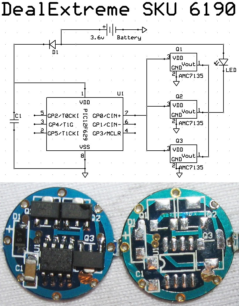
Its clear that the capacitor holds the power while the power is down in the ON-OFF-ON cycle that changes levels.

But then what happens? I didn't knew, so I posted a question in a Microchip Related Forum (Thanks Alain & Others!!) to see if someone else was able to help me.

The solution was found in less than a couple of hours, but it took ME a couple of days to understand it :D

Here is the gist of it, to understand the following, some knowledge of PIC programming is needed.

The PIC chips (12F629 in this case) have a Brown-Out Detection feature that can be enabled at programming time by setting a bit in the configuration register. Its called the BODEN bit (Brown-out Detection ENABLE)

Then we have the capacitor that performs two functions in the circuit:
1) keep power when battery power is lost
2) by carefully selecting its value, you allow the uC to survive n milliseconds

Then we have the Brown-Out and Power on Reset bits at the PCON register.

In normal conditions, when the uC starts for the first time or when power was lost for a long time this bit is set at 0 (datasheet: TABLE 9-6: INITIALIZATION CONDITION FOR SPECIAL REGISTERS)

BUT, here is the KEY, if power was lost but our capacitor managed to keep the uC running in the ON-OFF-ON with voltage below vBOD (Brownout voltage, see datasheet) but above vreset (below this value uC cold resets) BOR will show that power was lost for a little while but then it was recovered.

To be able to detect changes in these bits, we must set them to 1 the line after we check their value, remember Brown-Out Reset restarts your program from the top, not from where it was running, the only difference this time is that the PCON register values aren't lost like what happens in a cold start.

The metacode would be something like this:

Code:
init configuration bit to enable BOD
init registers to proper values 
(depending on your program, main loop needs)

if PCON.1=1 and PCON.0=0 then this means BOD was detected
set these bits to 1
mainloop
your payload here
loop
end

I hope this help some of you guys to develop new drivers, I hope I can finish mine :)

Another option can be used: instead of building a driver from scratch, why not reprogram already made ones to suit your need :)

I must say thanks again to the people that helped me in this quest to learn new stuff, without them I would be still scratching my head.


Pablo
 

TranquillityBase

Flashlight Enthusiast
Joined
Jun 12, 2005
Messages
3,741
Another option can be used: instead of building a driver from scratch, why not reprogram already made ones to suit your need :)

+1 :twothumbs

Great thread Pablo!
 

zipplet

Flashlight Enthusiast
Joined
Dec 11, 2006
Messages
1,139
Location
Ireland
I've been looking into this due to my own driver design. Initially I wasn't going to use the brown out detect but a second signal line to measure the voltage before the diode (while the PIC still has power).

I think I'll use this method now as it's cleaner, thanks!
 

PEU

Flashlight Enthusiast
Joined
Feb 26, 2004
Messages
3,600
Location
Buenos Aires / Argentina (I like ribs)
With the method I described, if you only need to change levels, there is no need for a main loop, for me its just an infinite loop to keep the uC running, because its all done in the detection stage.

[dream mode on]
My hope is that someone with better programming skills than me, help our community to develop a customizable firmware, for many of the cheap drivers available these days, most of them based in PIC12F629, something like Open Source Hardware.

I know its possible because is being done in a lot of areas, replace OEM firmware with custom ones (Sony PSP, iPOD, Linksys Routers, etc)

I suggested this years ago, but maybe I was a little ahead of time :)


Pablo
 

WildChild

Flashlight Enthusiast
Joined
Apr 26, 2005
Messages
1,424
Location
Québec, Canada
With the method I described, if you only need to change levels, there is no need for a main loop, for me its just an infinite loop to keep the uC running, because its all done in the detection stage.

[dream mode on]
My hope is that someone with better programming skills than me, help our community to develop a customizable firmware, for many of the cheap drivers available these days, most of them based in PIC12F629, something like Open Source Hardware.

I know its possible because is being done in a lot of areas, replace OEM firmware with custom ones (Sony PSP, iPOD, Linksys Routers, etc)

I suggested this years ago, but maybe I was a little ahead of time :)


Pablo

Is an infinite loop very power hungry with this IC? Usually, on a PC, an infinite loop tops the CPU at 100% level and is very power hungry...
 

zipplet

Flashlight Enthusiast
Joined
Dec 11, 2006
Messages
1,139
Location
Ireland
Well I already made a thread elsewhere recently about my own design and I see no reason to not release the source code + hex file when it's complete for the benefit of the community :) Others should do this too.

Such a low powered PIC uses negligable power but they can be put to sleep using a sleep instruction, waiting for an interrupt. This is probably best.
 

PEU

Flashlight Enthusiast
Joined
Feb 26, 2004
Messages
3,600
Location
Buenos Aires / Argentina (I like ribs)
Im using PIC12F683 because it has a PWM subsystem built in hardware, a nice feature, because you set it and then forget.

While testing the software for my driver, I noticed that a couple of bits from the STATUS register must be also be checked, so if you use this uC, keep in mind this too :)

The infinite loop is not power hungrier than other operations, so don't worry.


Pablo
 

MrAl

Flashlight Enthusiast
Joined
Sep 9, 2001
Messages
3,144
Location
New Jersey
Hello,

Hi Pablo how ya been?
What are you trying to build here, as what do you want it to do?

Yes i agree, an infinite loop in a PIC is much different than in infinite
loop in a PC, as for the PIC this is a typical operating condition, while
for the PC it means something is wrong somewhere.
There is one exception to this rule however, and that is when you want
to conserve power when the PIC is not being used (off or whatever but
power is still supplied). In this case you can 'shutdown' the PIC and
conserver battery power, then wake it up later if something has to be
done.
 

warlord

Enlightened
Joined
Feb 22, 2008
Messages
362
Location
Northern Illinois
Another option can be used: instead of building a driver from scratch, why not reprogram already made ones to suit your need :)
Pablo

Exactly! If you'll notice DX sku's 7612 and 6190 are exactly the same. The only difference it that one PIC is programmed with 5modes and the other is programmed with 16modes in 3 groups.

Maybe it's time I get into PIC programming...
 

Mr Happy

Flashlight Enthusiast
Joined
Nov 21, 2007
Messages
5,390
Location
Southern California
Maybe someone can answer a question that's been puzzling me. How do you get the program into a SMT chip, especially one that's already mounted on a board?

With a DIL package you could plug the chip into the programmer socket, load the program, and plug it back into its normal place. But SMT chips need soldering, they don't even have sockets. Does it mean there has to be an on-board programming interface on the actual driver? And where would that fit on a miniature driver board?

I'm sure there's an obvious answer here, but I'm not quite seeing it...
 

zipplet

Flashlight Enthusiast
Joined
Dec 11, 2006
Messages
1,139
Location
Ireland
In circuit serial programming (ICSP).

All modern PICs support it, it requires soldering a few wires (MCLR, CLK, DAT, GND, VCC) to the target circuit or chip.

Alternatively, you can get adapter sockets for small SMT devices to program them using a socket based programmer for use before you solder the device into your circuit.
 

linterno

Enlightened
Joined
Dec 19, 2007
Messages
348
Pablo:

Did you try to read the original program from PIC12F629? Where you able to do this? Did you measure the capacitor capacity? Did you try to program the device using ICSP?

Sorry for so many questions.

Juan C.

EDIT. Fixed Pablo's name. It was wrong before.
 
Last edited:

warlord

Enlightened
Joined
Feb 22, 2008
Messages
362
Location
Northern Illinois
:thinking:So when are we going to get the full "How-to" treatment?

You know, the details of which drivers to buy and how to pull and program our own PICs?
 

PEU

Flashlight Enthusiast
Joined
Feb 26, 2004
Messages
3,600
Location
Buenos Aires / Argentina (I like ribs)
Pablo:

Did you try to read the original program from PIC12F629? Where you able to do this? Did you measure the capacitor capacity? Did you try to program the device using ICSP?

Sorry for so many questions.

Juan C.

EDIT. Fixed Pablo's name. It was wrong before.

No, and I don't plan to, that would be pirating their firmware. I used the schematic in the 1st post to learn and then explained what I found and what I was teached by asking in other forums.
Regarding ICSP I need to build some kind of connector to reprogram the 12F629 without removing it from the board, as soon as I do it, I will let you know my findings.
Worst case is having to remove the PIC, but the idea is to avoid that.

:thinking:So when are we going to get the full "How-to" treatment?
You know, the details of which drivers to buy and how to pull and program our own PICs?

As I said, my coding skills arent enough to reprogram one of DX boards, so I made my own using a slightly better microprocessor.

For anyone versed in C or ASM for PICs generating a HEX file to reprogram DX converters would be a piece of cake. I provided all the information needed to do the ON-OFF-ON detection.


Pablo
 

PEU

Flashlight Enthusiast
Joined
Feb 26, 2004
Messages
3,600
Location
Buenos Aires / Argentina (I like ribs)
Hello,

Hi Pablo how ya been?
What are you trying to build here, as what do you want it to do?

Yes i agree, an infinite loop in a PIC is much different than in infinite
loop in a PC, as for the PIC this is a typical operating condition, while
for the PC it means something is wrong somewhere.
There is one exception to this rule however, and that is when you want
to conserve power when the PIC is not being used (off or whatever but
power is still supplied). In this case you can 'shutdown' the PIC and
conserver battery power, then wake it up later if something has to be
done.

Hi Al, sorry for not replying to your post earlier, how are you doing? hopefully fine!! :)

Im designing a new flashlight and I wanted to build my own converter in the process, so these are my findings and since I was helped in other forum I wanted to do the same here.

You are right on with the differences in the infinite loops, in this case if I put the uC to sleep all its functions would be disabled till I wake it up again, so putting it to sleep is a no go, we need it running.
The sleep function is usefull when you have the uC powered all the time and you use a soft turn on/off. In the off state, its a must to keep it consuming the smallest amount of current or else the batteries would drain.
Consumption in some uC's in the sleep state, are in the order of uA, far less than the batteries self discharge.


Pablo
 

MatajumotorS

Enlightened
Joined
Oct 24, 2006
Messages
263
Location
Latvia
Since DJPark presented us with the POP driver concept (and then it was used by a myriad of other drivers) it was a mistery to me how to know when the circuit lost its power. Found many solutions to this problem, but none of them were as elegant as the original idea.

The PIC chips (12F629 in this case) have a Brown-Out Detection feature that can be enabled at programming time by setting a bit in the configuration register. Its called the BODEN bit (Brown-out Detection ENABLE)

Then we have the capacitor that performs two functions in the circuit:
1) keep power when battery power is lost
2) by carefully selecting its value, you allow the uC to survive n milliseconds

Then we have the Brown-Out and Power on Reset bits at the PCON register.

In normal conditions, when the uC starts for the first time or when power was lost for a long time this bit is set at 0 (datasheet: TABLE 9-6: INITIALIZATION CONDITION FOR SPECIAL REGISTERS)

BUT, here is the KEY, if power was lost but our capacitor managed to keep the uC running in the ON-OFF-ON with voltage below vBOD (Brownout voltage, see datasheet) but above vreset (below this value uC cold resets) BOR will show that power was lost for a little while but then it was recovered.

To be able to detect changes in these bits, we must set them to 1 the line after we check their value, remember Brown-Out Reset restarts your program from the top, not from where it was running, the only difference this time is that the PCON register values aren't lost like what happens in a cold start.

The metacode would be something like this:

Code:
init configuration bit to enable BOD
init registers to proper values 
(depending on your program, main loop needs)
 
if PCON.1=1 and PCON.0=0 then this means BOD was detected
set these bits to 1
mainloop
your payload here
loop
end

I hope this help some of you guys to develop new drivers, I hope I can finish mine :)

Another option can be used: instead of building a driver from scratch, why not reprogram already made ones to suit your need :)

I must say thanks again to the people that helped me in this quest to learn new stuff, without them I would be still scratching my head.


Pablo

Great info on Brown-Out, i will try to use it :huh:
 
Last edited:

warlord

Enlightened
Joined
Feb 22, 2008
Messages
362
Location
Northern Illinois
No, As I said, my coding skills arent enough to reprogram one of DX boards, so I made my own using a slightly better microprocessor.

For anyone versed in C or ASM for PICs generating a HEX file to reprogram DX converters would be a piece of cake. I provided all the information needed to do the ON-OFF-ON detection.


Pablo

Aw nuts! I was hoping that'd you or we (as a group) could develop a simple how to. You know. Instructions on what to buy. Basic primer in coding and a piecemeal coding chart where you could patch together driver settings from the code chart to make a driver to function as desired.

This is much more interesting than just swapping out drivers...
 

Latest posts

Top