You are using an out of date browser. It may not display this or other websites correctly.
You should upgrade or use an alternative browser.
You should upgrade or use an alternative browser.
Maglite SSC P7. How to. A sort of guide.
- Thread starter StefanFS
- Start date

Hi Stefan, Thanks for this write up. This is going to be my first DIY flashlight mod. I ordered those driver boards from DX, 3 P7 emmitters, 3 heat sinks, wire, and have 3 3D mag hosts. Once everything arrives I will get started. One question I have is on connectiong th drivers together. Do I need to remove the diode on the slave and replace it with a jumper? I am just a bit confused on all those connections and making sure I get them right.
StefanFS
Flashlight Enthusiast
Unfortunately I ordered some 18650's before your reply. You mentioned something about a spring mod to make them work, can you elaborate?
Deanodize the interior of the tailcap with lye solution (drain cleaner/sodium hydroxide and hot water. Careful as it's toxic and dangerous to get on skin or in eyes) or sand the anodizing until you get bare metal. Cut and shape the spring so it fits in the bottom of the tailcap, I'll try to get a pic up.
--------------------------
Justin Case,
I have noticed that three D-size NiMH manage to hold up under load much better than three C-size, that's where the 4 x C idea comes from, to stay in regulation longer. A contributing factor is also the arguing and bickering that's been going on at times about these drivers and how to use them correctly. You also need to factor in real world losses in wiring-switch-drivers-solder points etc. A standard GP 9000 mAh D cell (not LSD) would set me back ~$22 per cell here. Sure I can order from eg. the US but shipping and fees make it about as expensive, D cells are heavy. The goal is as you say to keep above the emitter vf, at a reasonable cost for the cells.
---------------------------
737mech,
not really necessary. I remove all diodes to get that last 0.15V or whatever it is, there are some different figures on what the diode really do to the setup. If you remove all the diodes you lose the reverse voltage protection. But the multimode driver board also have the protection diode if you do a multimode setup, so why leave the diodes on the attached board/s with the extra AMC chips?
Last edited:
Justin Case
Flashlight Enthusiast
- Joined
- Mar 19, 2008
- Messages
- 3,797
Originally, it appears you had to modify (grind away some centering ribs, enlarging the holes for the wires, etc) an existing P4 heat sink to use for the P7 since dedicated P7 sinks didn't exist at the time.
When I look at the various sinks now available (e.g., LiteMania) for both P4 and P7 emitters, it seems that the pedestals for the P7 heatsinks are taller than for the P4 sinks. Did you find this to be any problem when you modified your P4 heatsink?
When I look at the various sinks now available (e.g., LiteMania) for both P4 and P7 emitters, it seems that the pedestals for the P7 heatsinks are taller than for the P4 sinks. Did you find this to be any problem when you modified your P4 heatsink?
Last edited:
StefanFS
Flashlight Enthusiast
Originally, it appears you had to modify (grind away some centering ribs, enlarging the holes for the wires, etc) an existing P4 heat sink to use for the P7 since dedicated P7 sinks didn't exist at the time.
When I look at the various sinks now available (e.g., LiteMania) for both P4 and P7 emitters, it seems that the pedestals for the P7 heatsinks are taller than for the P4 sinks. Did you find this to be any problem when you modified your P4 heatsink?
No that's never been a problem. They seem to be about the same height, all of them (or rather high enough). The only problem have been when I adapt P7 heatsinks to use MC-E by taking off material from the pedestal. I mainly use heatsinks sold by H22A, but I've used a few others as well.
Justin Case
Flashlight Enthusiast
- Joined
- Mar 19, 2008
- Messages
- 3,797
Thanks. I went ahead and filed off the centering ridge on my 4sevens P4 CMag heat sink and glued on a DSW0I-bin P7 using Arctic Alumina epoxy (I would have considered Arctic Silver, but removing the centering ridge exposed bare aluminum).
4sevens P4 CMag heat sink on the right, P7 DMag heat sink on the left.
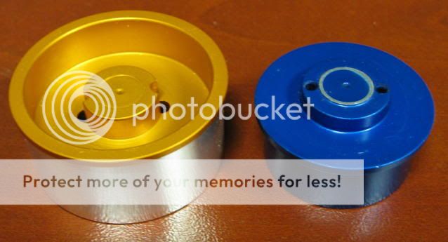
P7 glued onto the P4 heat sink. I used 24 gauge wire, which barely fits past the P7.
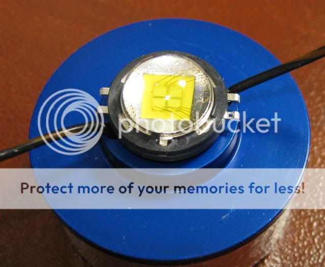
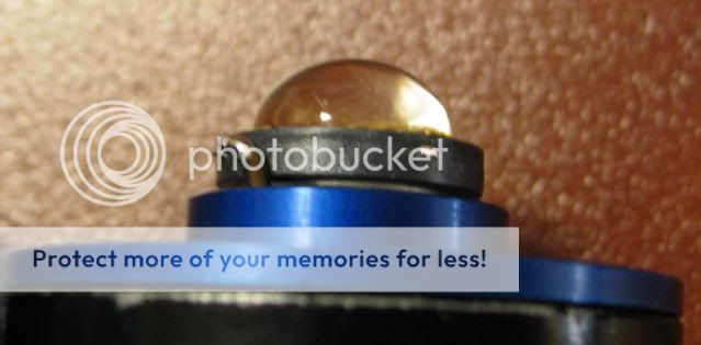
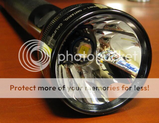
The result.
4sevens P4 CMag heat sink on the right, P7 DMag heat sink on the left.
P7 glued onto the P4 heat sink. I used 24 gauge wire, which barely fits past the P7.
The result.
Last edited:
Hi,
Need some help with the drivercombos, I cant get more than 1.5-1.6A from fresh 18650 (blue trustfire). I tried the first page 1A driver + 1400mah driver sanwitch, no more than the 1.6A. Then I tried 2x 1400mah drivers in parallel (diodes removed), again 1.6A max. Is it even possible to get more than 1.6A from single 18650 lion cell? thanks
Driver is DX's 5mode 7135 driver, the "new model" (check thread https://www.candlepowerforums.com/threads/228939)
1400mah chips, are also new, but I think that exactly same than the old blue ones.
Led is from KD P7 "CSXOI"
Is only option to buy some D lions?
Last edited:
StefanFS
Flashlight Enthusiast
Hi,
Need some help with the drivercombos, I cant get more than 1.5-1.6A from fresh 18650 (blue trustfire). I tried the first page 1A driver + 1400mah driver sanwitch, no more than the 1.6A. Then I tried 2x 1400mah drivers in parallel (diodes removed), again 1.6A max. Is it even possible to get more than 1.6A from single 18650 lion cell? thanks
Driver is DX's 5mode 7135 driver, the "new model" (check thread https://www.candlepowerforums.com/threads/228939)
1400mah chips, are also new, but I think that exactly same than the old blue ones.
Led is from KD P7 "CSXOI"
Is only option to buy some D lions?
You need better cells. I tested one of my 1D with 3.2A driver with the following cells:
AW 18650 new: 2.3A
Grey Trustfire 18650: 1.94A
KD D LiION unprotected: 3.2A
4 x eneloop in fm holder: 3.14A
3 x eneloop in holder 2.5A
So with an 18650 cell that works best with lower current draw applications your numbers are reasonable.
The new multi mode drivers work the same way, they're only somewhat redesigned, I use the 2 level variety (sold by KD).
Other options that should take a high current draw are IMR and emoli cells. The SSC P7 and MC E emitters are demanding.
So, can we make some conclusions that grey trustfires are better than blue ones? Just thinking, that just under 2A could be enough for ultrafire C2 P7 mod. Or AW's for that mod.:candle:
But anyways, thanks a lot Stefan. The problem is the battery, not my solderings etc. :thinking:
ForeverZ01
Newly Enlightened
- Joined
- Mar 21, 2009
- Messages
- 6
I FINALLY got my drivers in and set everthing up and had it all working and then i think i touched the aluminum reflector on both contacts of the led and then there was smoke. It burned a wire that went from the battery negative on the multimode driver to the battery negative on the slave sandwich. I replaced the wire and now all i get is low power, the different modes arent working anymore. Should i just forget the multimode and set up a sandwich running 2.8 amps and just run with that or should i order another multimode driver and wait another two weeks for it to come from hong kong, Please Help. thanks
StefanFS
Flashlight Enthusiast
ForeverZ01,
That depends on what you plan to do with your light, but a one level light works well enough... About multimode check my pm.
That depends on what you plan to do with your light, but a one level light works well enough... About multimode check my pm.
You need better cells. I tested one of my 1D with 3.2A driver with the following cells:
AW 18650 new: 2.3A
Grey Trustfire 18650: 1.94A
KD D LiION unprotected: 3.2A
4 x eneloop in fm holder: 3.14A
3 x eneloop in holder 2.5A
So with an 18650 cell that works best with lower current draw applications your numbers are reasonable.
The new multi mode drivers work the same way, they're only somewhat redesigned, I use the 2 level variety (sold by KD).
Other options that should take a high current draw are IMR and emoli cells. The SSC P7 and MC E emitters are demanding.
Ok, I tryed with KD protected D lion (3.98V). Mesured only 1.35A at tailcap. :thinking: I think that is time to check my solderings, can someone mark the solderin points for the 2.4A config with new 5 mode driver board? thanks!
Like this:
And here is with new board. Someone please complete this. Thanks!

Edit: Is this right?
I just tested with fullycharged (4.23V) D lion and only 1.7A. :/
Last edited:
Just got done making this light with the 16 mode driver board in the link. The board was laid out a bit differently than the one originally posted but I was able to figure out the connections by looking at the pictures here. My light works but not like the instructions. The instructions for the driver are "To switch mode, stay in any mode for no more than 2 seconds then switch off. The next time the light is turned on it will enter the next mode." My light will not switch modes like this. I have to repeatedly press the switch on and off a few times to get to the mode I want (low, med, or high). I can get it to change mode groups no problem. It works just like its supposed to if I dont press the switch all the way in before it clicks. Any thoughts?
Last edited:
StefanFS
Flashlight Enthusiast
ashrakki,
your connections look good. It should not matter, but just to rule it out, switch the connection from + on the slave board to the AMC chip marked 35E on your multimode driver.
737mech,
not sure what you mean, sounds like how my drivers work. Steps through the levels. Does it remember the level if you have it on for more than 2 sec?
your connections look good. It should not matter, but just to rule it out, switch the connection from + on the slave board to the AMC chip marked 35E on your multimode driver.
---------------------------------------------------------------
737mech,
not sure what you mean, sounds like how my drivers work. Steps through the levels. Does it remember the level if you have it on for more than 2 sec?
No it does not remember the level. Thats just it, I never know what level its going to be on.Here is the results of my light turned on waiting 6-7 seconds then turned off then back on 20 times.
1.low
2.low
3.med
4.med
5.high
6.med
7.high
8.med
9.med
10.low
11.low
12.high
13.low
14.low
15.med
16.high
17.low
18.med
19.high
20.low
see what I mean? It's just random. Any help would be great.
1.low
2.low
3.med
4.med
5.high
6.med
7.high
8.med
9.med
10.low
11.low
12.high
13.low
14.low
15.med
16.high
17.low
18.med
19.high
20.low
see what I mean? It's just random. Any help would be great.
StefanFS
Flashlight Enthusiast
737mech,
nothing to do. Contact the seller for replacement. Strange, I never had any problems with the AMC based drivers. I think the programming is off in your specimen.
nothing to do. Contact the seller for replacement. Strange, I never had any problems with the AMC based drivers. I think the programming is off in your specimen.
ashrakki,
your connections look good. It should not matter, but just to rule it out, switch the connection from + on the slave board to the AMC chip marked 35E on your multimode driver.
---------------------------------------------------------------
I did that and there was no difference. Again 1.7A max with D lion and even TR18650 I get about 1.6A. Can Emitter Bin do something like that if its "J"? Although I ordered CxxxI bins from Kai...

Here is pic, but I really think that the problem isnt my solderings, because I tested with 2x1400mah boards parallel and same 1.7A.
wtf. Has anybody seen anything like that? :duh2: Help Needed.


And there isn't any bridges, checked that...
Last edited:
Thanks for your help. I have 4 of these 16 mode drivers and I just tried another one with the same results. Like I said they are a bit different in layout. Here is a picture. Maybe someone can help me with how to wire the newer style driver since its different than the ones in post #1.737mech,
nothing to do. Contact the seller for replacement. Strange, I never had any problems with the AMC based drivers. I think the programming is off in your specimen.
