XM-L question on heat

Rekkie

Newly Enlightened
Joined
Oct 14, 2010
Messages
53
Hi, I've been around this forum for 2 years or so. I have not posted much
but learned A LOT!!lovecpf, and decided it's time to mod/build me me a light. I would like to use some Cree XM-L LED(s) but I am lost when it comes to heat sinks.:thinking: What is the heat buildup like on these emitters when driven at say 3Amps and/or less Amps? and what size heat sink would I need for a single and/or triple applications when driver at full Amps?

I have done many searches on the forum but I don't always have the time to properly read through all the threads. If there's any threads or links that can help regarding heat sinks and LED heat build up it would be much appreciated!!

Many thanx in advance:thanks:
Eddie
 

lite1

Newly Enlightened
Joined
May 26, 2011
Messages
5
WHat Host/Flashlight you are going to use.?

It also depend on your run time. If you are look for long "on" time you are going to need a good size heatsink.
 

Rekkie

Newly Enlightened
Joined
Oct 14, 2010
Messages
53
I have a very ambitious idea: to make a hybrid bike light housing (bar mount) that could fit onto a MAG 4C tube using 3*XM-L LEDs and Cute3X http://www.cutter.com.au/proddetail.php?prod=cut1064optics. So I'm looking at about just over an hour of "on" light on max drive with 3 of these batteries: http://www.batteryspace.com/limnnirechargeable26650cell37v4000mah10arated148wh.aspx and a Taskled h6flex driver. It should give just over 7hrs of runtime if driven to deliver +/- 1000Lm. So it would be a custom made housing, hence the question on heat buildup. However I am not going to be using it on Max drive (3A) all the time, but it would be nice to know that the housing can dissipate the heat if I ever need to run it at max for that long.

I had a look at this:http://forums.mtbr.com/showthread.php?t=680870 and it seems to heat up really fast when there is no air moving over it (when driven at max). But it does give me some idea on the heat sink side of it.
 

bbawkon

Newly Enlightened
Joined
May 20, 2011
Messages
73
Well, at 3 amps, the XML will produce about 8 watts of heat. perhaps a little less, perhaps a little more - it does vary based upon the exact Vf of the emitter(s). for 3 of them, figure you're going to deal with about 25 watts of heat.

In a small package, 25 watts is quite significant. You'll need a good deal of surface area, and you'll need a thermal path capable of getting the heat from the emitters to the surface.

Designing a proper heat sink and thermal path is not horribly difficult, but it's not trivial either. Companies spend tens of thousands of dollars for Multi-Physics simulation software (Ansys, Comsol, Solidworks Flow Sim, etc.) in order to figure out these problems. It can be done by hand, but being of the computer age, I can't even imagine doing it that way for anything beyond a few watts, a very few sources, and a simple heat sink geometry. I recently designed a heat sink that is about 15" x 7" x 2.5" with (a LOT of) forced convection. It can dissipate 2500 watts of heat (yep, 2.5KW) while sustaining only a 10 degree C heat rise. Aluminum wasn't even close to being up to the task - solid copper was needed. Simulation software told me that aluminum wasn't an option before I ever touched a piece of metal, and then based upon the output from the fans, the simulation software iterated through different fin thicknesses and densities to discover the best arrangement. in short, sim software is awesome - and more accurate than you might think. Real world testing of the designed heat sink has shown the sim software was accurate to within a few percent.

If you mock up your intended design, I can run the model through the simulation at work for you. It doesn't take that long to do, and I'm happy to help.

Ben
 

Rekkie

Newly Enlightened
Joined
Oct 14, 2010
Messages
53
Hi Ben

That would be REALLY GREAT!! I have only done some very conceptual sketches of it so far, since I'm not to clued up with what is needed regarding the size and number of fins etc. But I figure I'll just have crack at it since I can now make a mistake and correct it before I build it for real. Will get around to it over the weekend. In which format do you need it: dwg./3ds./dxf./...?? I can do it 2D and/or 3D. Can you PM me your contact details?

:thanks:
 

bbawkon

Newly Enlightened
Joined
May 20, 2011
Messages
73
Hi Rekkie,

Glad to help. 3D would be preferred, without a doubt. I can take sldasm, sldprt, step, iges, stel, proE, unigraphics, inventor, and solidedge.

I'll PM you my offline email address.

Ben
 

Curt R

Enlightened
Joined
Mar 22, 2009
Messages
486
Rule of thumb is that you would require 10 square inches of heat
sink, (Aluminum), for every one watt of heat generated. That is
the basic ideal. However much less can be used if you are willing
for the assembly to get a little hotter. The phosphors used in the
Cree XML can tolerate much hotter temps than those from just a
few years ago. That is the limiting factor of white light LED life.

When we build flashlights we have to break the rules otherwise the
flashlight would be huge. Running the light with 3 square inches of
surface area per watt will still give you thousands of hours of light.

Do not worry about being ultra correct, build it and have fun. Or get
pre-manufactured flashlight heads or drop-in's and mount them to your
design.

Curt
 

Rekkie

Newly Enlightened
Joined
Oct 14, 2010
Messages
53
Got some pics of my progress, will post them soon!
Many thanks to Ben for doing some thermal simulations for me. :thumbsup: Without that I would have made me a light that generates Lumen in the form of heat rays.

"...Do not worry about being ultra correct, build it and have fun..."

I sometimes forget that. Thanks Curt!
 

Rekkie

Newly Enlightened
Joined
Oct 14, 2010
Messages
53
Some images of my progress: For consistency I chose the images of the thermal simulations that where done @ 30W and 17 degree C ambient, air flow is directly head on and at various speeds as will be stated.

Will start a build thread as soon as I get going with making it.

1) 1st concept_2MPH air flow_housing running @ 267 degree C
Eduan_Adams


2) 2nd Concept_2MPH air flow_made no difference


3) 3rd concept_2MPH air flow_ dropped the running temp by 40 degree C


4) 3rd concept_19MPH air flow_ running temp 60 degree C


5) Some images of the 3D model


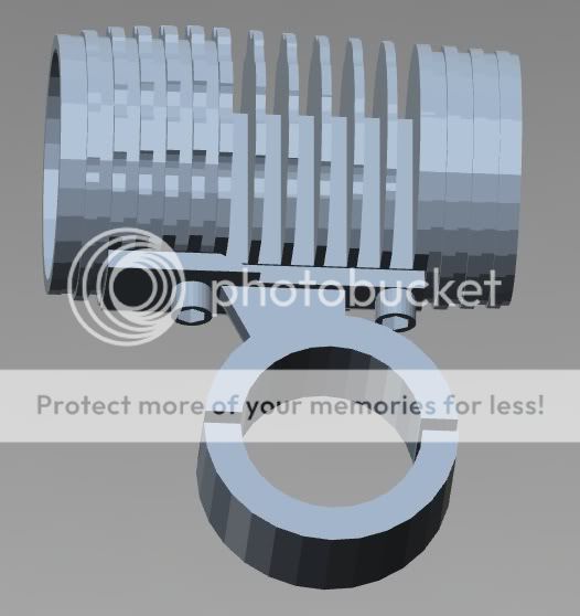
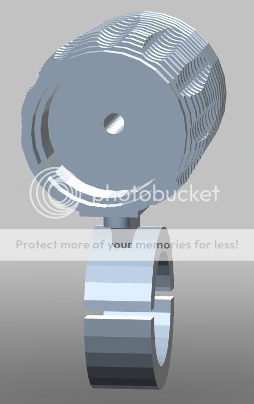
From the above model I have the fins @ 3mm thickness and spacing...and it performs well at 19MPH air flow (and being a bike light I would only use high mode at that and faster speeds). Had a thought and made the fins 2mm thick and 2mm spacing...it has a lot more surface area, but I'm not to sure if it improve the thermal performance...as in will the 2mm space between the fins be enough for better air flow or worse? Plus it would be more difficult to machine...but not impossible.

Some images of the 2mm fins


All comments/suggestions welcome!!
 

Curt R

Enlightened
Joined
Mar 22, 2009
Messages
486
Fins that are too thin and spaced closely together restrict
thermal dissipation at low air flow rates. This is less of a problem
when a bike is moving, but when stopped the flow of the air is
vertical and the design will act as more of a solid than a finned
design.

If the internal space could be reduced, then the side fins could be
machined vertically instead on horizontally. Try to keep the interior
as small as possible to help conduction down the length of the head.

It is also best if the head is thermally isolated from the electronics
and the battery.

Curt
 
Last edited:

Rekkie

Newly Enlightened
Joined
Oct 14, 2010
Messages
53
The internal space in the back will be where the driver would be fixed. Will be using a H6flex, which has various thermal protection trip points (dims the LEDs to much lower level) so it has to be thermally connected to the LEDs. But I don't want to rely solely on the driver for thermal protection. I'd rather want the housing to do most of the cooling and have the driver's thermal protection as the "last line of defense". The size of the space is at it's minimum to fit the driver. On max it will be putting out close to 3000 Lumen which will only be needed for very fast riding as I will be using it on both my road bike and MTB.

The housing is quite small, only 45mm in diameter and 65mm in length so I know I'm way over the boundaries for the amount of heat it needs to dissipate. I just want to achieve as best possible thermal performance from it hence the hassling on fins. The 3mm fins and spacing is good when the light is on max (30W) with 19MPH air flow, LED's running at just under 60 degree C. Now given the same 19MPH air flow and 30W from the LEDs how will the 2mm fins and spacing do? ...or am I to petty about this?

Eduan
 

Curt R

Enlightened
Joined
Mar 22, 2009
Messages
486
Our FR800 and FR1000 are about the same size with a single LED driven at
10 watts. after several minutes at full power the outside of the fins heat
up to 170 degrees F. We use a 12 mm thermal spacer between the LED heat
sink and the electronic compartment. Other flashlights use an electronic
thermal protection systems. The difference is that our flashlights can be run
at full power constantly while the others start to dim after on 2.5 minutes or so.

I look at your size/power with great reservation. I have seen where theoretical
designs did not work. The best example is the just released SF light that uses the
MCE or P7 LED. It took them almost three years and many failures to bring it to
market. And when they did it was under powered, over priced and 6 months obsolete.

I could see your design working with a 65mm diameter. Also you are limiting the output
with too small diameter optics. Throw will be close to 50 meters or a little more, at 19 mph
that distance is covered very quickly. About 5 seconds.

Just reread your first post and using a 4C mag battery compartment. Without that
thermal spacer you will destroy those batteries from the heat traveling down the tube.

Curt
 
Last edited:

Rekkie

Newly Enlightened
Joined
Oct 14, 2010
Messages
53
Oh yes I forgot to mention that I realized very soon that the idea of it being a hybrid bike light/ flashlight was not going to work due to size issues. It's now a full on bike light only.

Some beamshots on max drive from other guys' lights with the optic I choose:


Don't think I will be having problems with throw... it reaches 175m in the last shot. It says "2800mm" on the photo, it should be 2800mah.

Eduan
 
Last edited:

octagonalman

Newly Enlightened
Joined
Jun 26, 2011
Messages
9
Would it be feasible to use the bicycle frame as an additional heatsink? I was thinking of using something like a cola can to interface between the primary heatsink and the bicycle frame.
 

Curt R

Enlightened
Joined
Mar 22, 2009
Messages
486
Thermal heat transfer is only good if the interface is thick
and a good conductor, also the frame needs to be a good
conductor also. If the frame is not Aluminum, the effort is
is more than likely a waste.

Curt
 

cdrake261

Enlightened
Joined
Jun 26, 2011
Messages
484
Location
Columbus, IN
Interesting concept, but if you scaled it back to one(maybe two) xm-l, you can reduce the overall unit size plus it won't get so hot
 

Rekkie

Newly Enlightened
Joined
Oct 14, 2010
Messages
53
Actually, three XM-L's do just fine. Test rigged it up a week or so ago, and it does not seem to get that hot. Rigged it up on a 65W Intel CPU sink, but I removed the fan , so only natural convection, basically no-flow and I placed it on a flat surface to further restrict airflow. Also spoke to a guy on MTBR who made a housing using vertical fins perpendicular to front airflow and his settled at 65 degree C after 15min or so while being stationary, ambient was temp was 12 if I remember correctly.

This is my version of that type of fin setup:
344.jpg


342.jpg


This one has about the same amount of fins so it might run similar.

If it gets too hot the thermal trip point of the Taskled will kick in. Also, 3000* lumen is INSANELY BRIGHT even with such a small optic, so don't think I will be running it on max that often.
 
Last edited:

Curt R

Enlightened
Joined
Mar 22, 2009
Messages
486
Keep us updated, knowledge is key in this business as to what
works in the real world and what does not.

Curt
 

Rekkie

Newly Enlightened
Joined
Oct 14, 2010
Messages
53
Sorry mate, been a while since I was on any forum, but guilty as charged.

I have a revised version in mind with a different mount I still need to model...trying to use the mount as an extra heat sink.

Ever think of making a QD option? If you made the mounting point accept a picatinny rail section, you could mount your lite to an Larue Tactical QD mount and attach the unit to the rail.

http://stores.homestead.com/Laruetactical/Detail.bok?no=117

Guaranteed lock-up and return to zero!

The price scares me:eek:
 
Top