darkavenger
Newly Enlightened
- Joined
- Apr 6, 2013
- Messages
- 27
Hello all!
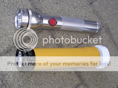
This all started out as a simple mod to an old light, however I'm being sucked in.
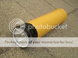
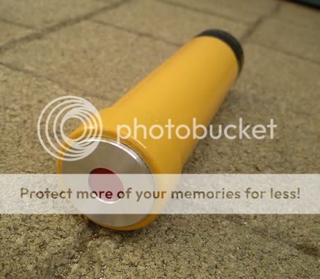
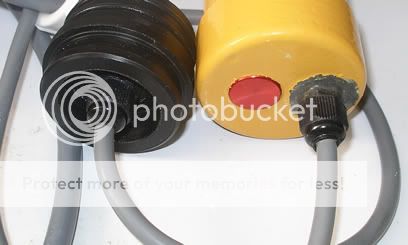
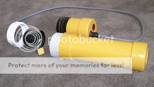
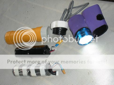
So I'm ready to jump into a canister light build. Almost. I've made progress toward a plan anyway. I've selected some parts to use:
Modded Maglite body cut down in size
3 x XM-L T5 neutral white (4500k) LEDs
3 LED reflector
3 Mode Boost/Buck 3 LED XML driver 30W 3A (3 LEDs in serial)
Heatsink (copper over aluminum?)
Lens - Boro Glass 5mm thick
Cable/Connectors
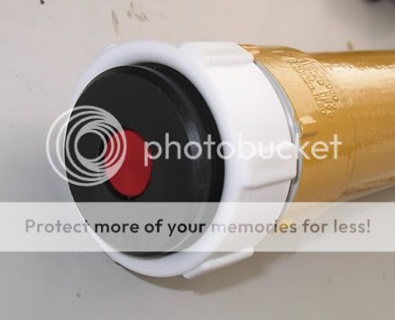
Switch (piezo)
Battery Housing
What I still need to figure out...
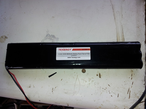
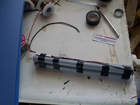
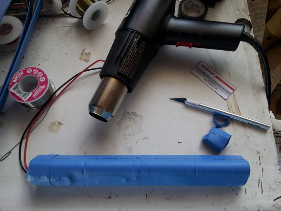
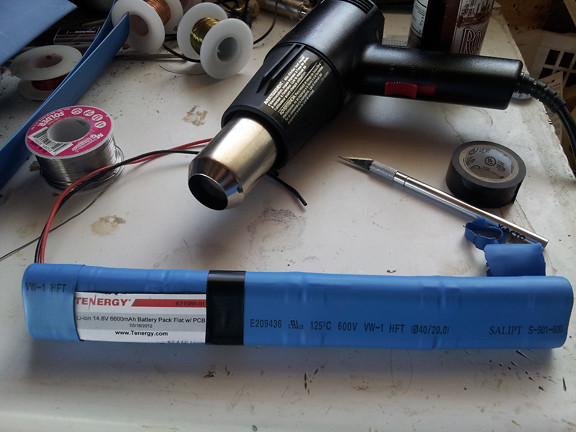
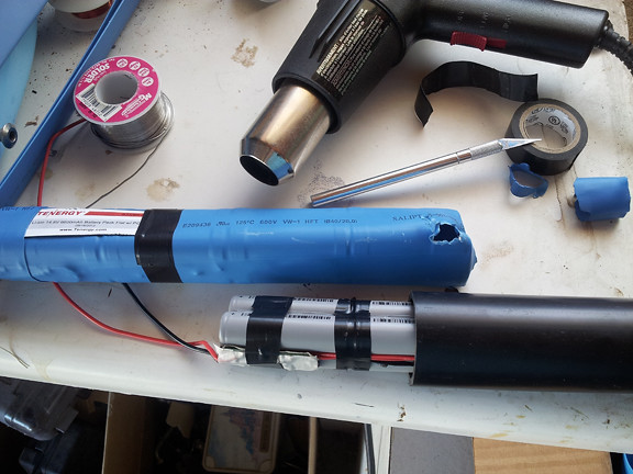
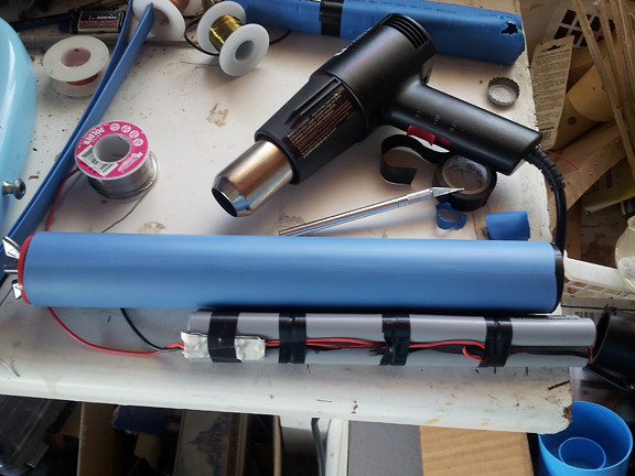
Battery Pack
Recharge system
I've been toying with the idea of filling the LED housing/Maglite body with mineral oil to reduce the effects of pressure and help the light's thermal properties. If everything is installed properly, this housing could be sealed fairly permanently with the oil inside. Any thoughts?
This all started out as a simple mod to an old light, however I'm being sucked in.
So I'm ready to jump into a canister light build. Almost. I've made progress toward a plan anyway. I've selected some parts to use:
Modded Maglite body cut down in size
3 x XM-L T5 neutral white (4500k) LEDs
3 LED reflector
3 Mode Boost/Buck 3 LED XML driver 30W 3A (3 LEDs in serial)
Heatsink (copper over aluminum?)
Lens - Boro Glass 5mm thick
Cable/Connectors
Switch (piezo)
Battery Housing
What I still need to figure out...
Battery Pack
Recharge system
I've been toying with the idea of filling the LED housing/Maglite body with mineral oil to reduce the effects of pressure and help the light's thermal properties. If everything is installed properly, this housing could be sealed fairly permanently with the oil inside. Any thoughts?
Last edited: