abvidledUK
Flashlight Enthusiast
Here's the original simple Mk1 version
https://www.candlepowerforums.com/posts/1599195&postcount=1
Here's the modified Mk2 version
Followed by the NEW Mk3 version....

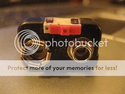
As you can see, it now has a switch fitted.
The main reason for this is to give it a very low level nightfinder glow mode.
There is a 150kΩ resistor (bleed resistor) fitted across the switch, so that a current of 0.02ma is just enough to give a glow in the dark facility.
You may notice blue at either end of the switch, under the epoxy, this is blue tack, to stop epoxy going into the switch mechanism, the first Mk2 prototype was very stiff to switch, for this very reason.

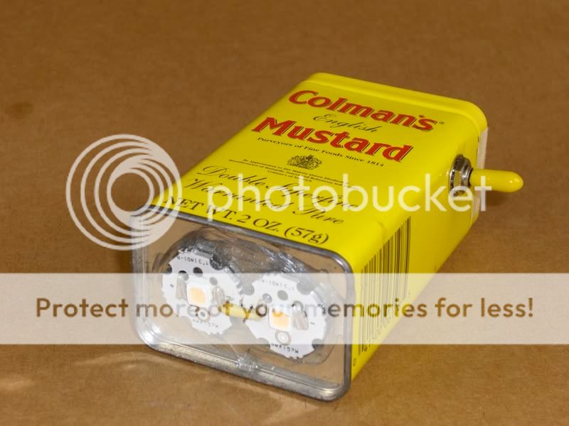
I did try 15,000 mcd (supposedly) LEDs, they were nowhere near as bright as the 16,000 mcd LEDs pulled from keychain lights, advertised as 16,000 mcds


Difficult to see, but the LED's are isolated from the centre switch connector, they are insulated in finished version.
The LEDs are connected at one end only, the other end of the LEDs is connected to the negative battery connector.


I further refined the epoxy, by tilting the assembly slightly after the first layer, worked well.
When touch dry, wrapping the epoxy with smooth insulating tape gave a very smooth finish.
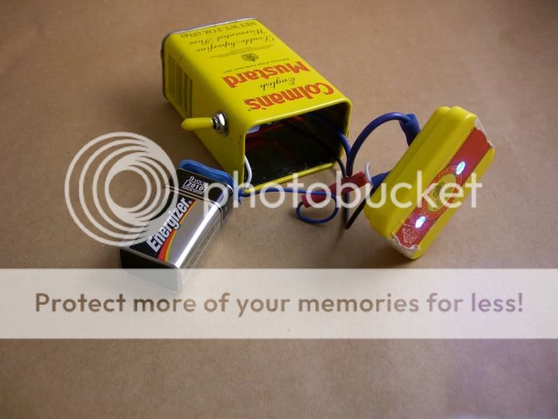
So, +9v into centre connector (2) of switch.
150kΩ across (1) & (3) (Switch OFF=Night Glow)
LED1 +ve to (3) (Full power)
LED1 -ve to LED2 +ve (in series)
LED2 -ve to -9v. (OK, 0v to be pedantic)

I already have the parts on order for the Mk3 version....
Clue:
I shall be using 2AA and 4AA battery boxes with PP3 connectors for a more professional finish, and more solid connectors. Boxes cut down to size then epoxied of course. 9v and 6v versions, series / parallel LEDs with appropriate resistors.
This is purely a hobby mod, I will NOT be going into production with these.
Have fun this weekend, then post your photo's here !!
https://www.candlepowerforums.com/posts/1599195&postcount=1
Here's the modified Mk2 version
Followed by the NEW Mk3 version....
As you can see, it now has a switch fitted.
The main reason for this is to give it a very low level nightfinder glow mode.
There is a 150kΩ resistor (bleed resistor) fitted across the switch, so that a current of 0.02ma is just enough to give a glow in the dark facility.
You may notice blue at either end of the switch, under the epoxy, this is blue tack, to stop epoxy going into the switch mechanism, the first Mk2 prototype was very stiff to switch, for this very reason.
I did try 15,000 mcd (supposedly) LEDs, they were nowhere near as bright as the 16,000 mcd LEDs pulled from keychain lights, advertised as 16,000 mcds
Difficult to see, but the LED's are isolated from the centre switch connector, they are insulated in finished version.
The LEDs are connected at one end only, the other end of the LEDs is connected to the negative battery connector.
I further refined the epoxy, by tilting the assembly slightly after the first layer, worked well.
When touch dry, wrapping the epoxy with smooth insulating tape gave a very smooth finish.
So, +9v into centre connector (2) of switch.
150kΩ across (1) & (3) (Switch OFF=Night Glow)
LED1 +ve to (3) (Full power)
LED1 -ve to LED2 +ve (in series)
LED2 -ve to -9v. (OK, 0v to be pedantic)
I already have the parts on order for the Mk3 version....
Clue:
I shall be using 2AA and 4AA battery boxes with PP3 connectors for a more professional finish, and more solid connectors. Boxes cut down to size then epoxied of course. 9v and 6v versions, series / parallel LEDs with appropriate resistors.
This is purely a hobby mod, I will NOT be going into production with these.
Have fun this weekend, then post your photo's here !!
Last edited:
") .
.