Can a driver board share a common ground with its own output?

spectral532

Newly Enlightened
Joined
Jan 15, 2010
Messages
8
Can I safely connect the Vin(-) and the Vout(-) terminals of a driver board together to form a common ground? I am attempting to power a case-negative laser diode, so effectively the negative lead is constantly in contact with the flashlight case. Therefore, the Vin(-) and Vout(-) would both be connected to the case. Would the driver still work properly under these conditions?

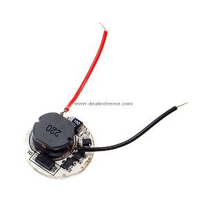
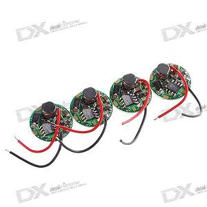
I plan on using one of these two drivers.
vbLkW.jpg
74Pg7.jpg

http://www.dealextreme.com/details.dx/sku.7882
http://www.dealextreme.com/details.dx/sku.3256
 
I think you'd just have a direct drive circuit. Every DX board I have owned directly connects +Vout straight to +B (which is +Vin).

By connecting -Vout to chassis ground (and connecting the LED too that node) you are just creating a direct drive circuit.

someone please correct me.:thinking: I am not sure how the circuit would behave in this scenario.
 
Well, if you have a DMM, you can measure the resistance between the output - and ground. If it's shorted, then it's already shorted to ground. If it's anything else, then there's probably a low side sense resistor, in which case it's not okay to short it to ground.
 
I think you'd just have a direct drive circuit. Every DX board I have owned directly connects +Vout straight to +B (which is +Vin).
That might be the case with 7135-based or other linear drivers, but not for any buck +/or boost drivers I've seen.

For the OP's question, if isolating the cases would be a real pain, there could be the option of a constant voltage driver, maybe using a resistor to regulate current to the laser diode. That way, they might be able to have a common ground, depending on the circuit details.
I seem to remember some DX or KD boost drivers being constant voltage, but can't remember whether they were single-mode drivers.
 
For a buck driver, as an example, the circuit topology has to have LED+ after the inductor. Thus, Batt+ and LED+ are not a direct-connect.

You can also examine the typical circuit topology for a boost driver, and come to the same conclusion.

Now, it is true that for the typical (non-isolated) flashlight driver, there is no explicit dielectric isolation between the inputs and outputs. But that IMO is somewhat of a fine point.

With respect to the OP's original question, there are some drivers that share a common ground and LED- connection. Two examples that come to mind are the Badboy Nexgen and the GD.

For DX3256, it is my understanding that it is now an AX2002-based buck driver, similar KD1640. Thus, LED- and ground are not the same thing. LED- has to connect in-between the LED and the current sense resistor.

Can't help you on DX7882.
 
For a buck driver, as an example, the circuit topology has to have LED+ after the inductor. Thus, Batt+ and LED+ are not a direct-connect.

Not necessarily. This 3W buck configuration has common Batt+ and LED+

a_68r.jpg


Same thing with common Vin(-) and the Vout(-), it doesn't matter whether buck or boost. It depends on the circuit design whether you can (or cannot) common either vBatt or GND.
 
Not necessarily. This 3W buck configuration has common Batt+ and LED+
That's an interesting circuit - laid out that way, it's more immediately obvious how it works than in some other circuits - you can see the ring of LED, diode and inductor, with the inductor trying to keep current flowing round the ring and through the LED in the off phase of the FET.

However, it's not as clear how the current sense works - in a more typical circuit, the current is always flowing through the sense resistor, but in that one, isn't it only flowing through it when the FET is on?
Is there some neat way to work out average LED current from average sense resistor current, even if input voltage varies over a wide range?
What was the chip involved?

Same thing with common Vin(-) and the Vout(-), it doesn't matter whether buck or boost. It depends on the circuit design whether you can (or cannot) common either vBatt or GND.
Presumably for constant current drivers, there's generally going to be a low-side current sense, unless there's a pressing reason to do otherwise, even if that might be partly just down to convention.
 
That's an interesting circuit - laid out that way, it's more immediately obvious how it works than in some other circuits - you can see the ring of LED, diode and inductor, with the inductor trying to keep current flowing round the ring and through the LED in the off phase of the FET.

However, it's not as clear how the current sense works - in a more typical circuit, the current is always flowing through the sense resistor, but in that one, isn't it only flowing through it when the FET is on?
Is there some neat way to work out average LED current from average sense resistor current, even if input voltage varies over a wide range?
What was the chip involved?

It is based on the Zetex ZXSC300/310. It is sensing the peak inductor current rather than the LED current. Note that the input (as opposed to output current) is held constant. I can also show a similar, more conventional (constant output current) configuration if you are interested.

a_68s.jpg
 
Is there anyway to modify the circuit of the DX 3256 so that it can share a common V(-) terminal? Isolating the diode would be a real pain for me. I think that I read somewhere that a op-amp (summing?) could be used to enable a common ground, but I'm not entirely sure how that would work.
 
Top