Nereus
Enlightened
After finishing this mod, I wanted to simplify the UI of the Fenix P1D-CE to dual level (first low, then high) and increase the low level runtime. I changed the converter to BB NG 750 – that is for high level. For long running low level there is direct drive mode.
Below you can see the schematics of the mod:
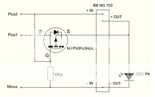
There is one resistor and one p-type MTP50P03HDL mosfet in there in addition to the BB NG 750 converter. The circuit works in the following way: battery minus is connected all the time. When plus1 is connected the mosfet turns on and the flashlight goes to DD mode. When the plus2 is connected in addition to plus1, the mosfet gate is pulled up and it is turned off. Meanwhile the converter gets current and the flashlight is in high mode.
The mosfet is installed in reverse: drain as input and source as output – reason for this is the body diode drawn to schematic. If the mosfet were connected in the usual way the body diode would be forward biased at high mode. Luckily on-state mosfet does not care if it's connected in the usual way or in reverse.
I measured that the on-resistance of the mosfet is less than 0,1 ohms at 2,8 volt gate-source voltage – low enough for the direct drive mode. However, that is not enough to make a good mosfet for this purpose. From the schematic you can see that also at high the mosfet gate gets biased. The biasing voltage is the difference between led forward voltage and under-load battery voltage. Assuming worst case scenario 2,2 v battery voltage and 3,6 v led Vf that's 1,4 volts. That's why I measured that the on-resistance at 1,4 volt gate-source voltage is 5000 ohms – high enough. So MTP50P03HDL suits nicely for the purpose. If it only were to-92 package… But I was lazy now and decided to use to-220 package MTP50P03HDL that I had at hand. I had to cut the heatsink of the mosfet in order to make it fit in the converter+led unit.
I started the mechanical part of the modding with drilling and filing the original "heatsink" away so that the converter+led unit case is only an empty "tube"

Below you can see the empty converter+led unit case and the new battery contacts:
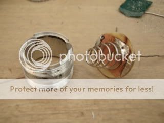
Here you can see the battery contact side of the converter+led unit. The plus1 contact is a bit taller than plus2 contact. That's why plus1 gets connected first and when screwing the flashlight head 1/4 turns more in the plus2 gets connected also.
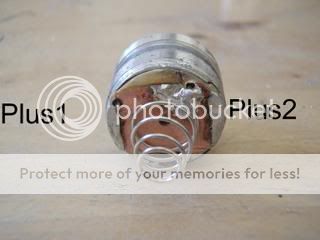
The battery is turned upside down because like that you can get two plus contacts through flashlight body. Battery minus is now connected with the spring shown in the photo above. I removed the original battery spring.
The original aluminium "heatsink" is only 1 mm thick at its thinnest point (immediately around the led). That's why I improved the thermal management by installing 2,5 mm thick copper heatsink, see below.
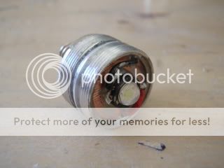
Here is a pic of finished mod:

I did a runtime test for the low level: 20 hours down to 50% and 40 hours down to useless (=can not longer navigate in a dark room with eyes not adjusted for darkness). See this thread for original converter performance: it is easy to calculate that the down-to-useless runtime at low should be some 15 hours, so we are seeing quite an improvement here. At high (750 mA) the runtime of my mod should be approximately 1 hour.
The beam is quite similar to that of my previous P1D-CE mod: smooth beam with no rings or other imperfections, same brightness at high also. The reflector is cut-down IMS20.
Thanks for looking!

-N
Below you can see the schematics of the mod:

There is one resistor and one p-type MTP50P03HDL mosfet in there in addition to the BB NG 750 converter. The circuit works in the following way: battery minus is connected all the time. When plus1 is connected the mosfet turns on and the flashlight goes to DD mode. When the plus2 is connected in addition to plus1, the mosfet gate is pulled up and it is turned off. Meanwhile the converter gets current and the flashlight is in high mode.
The mosfet is installed in reverse: drain as input and source as output – reason for this is the body diode drawn to schematic. If the mosfet were connected in the usual way the body diode would be forward biased at high mode. Luckily on-state mosfet does not care if it's connected in the usual way or in reverse.
I measured that the on-resistance of the mosfet is less than 0,1 ohms at 2,8 volt gate-source voltage – low enough for the direct drive mode. However, that is not enough to make a good mosfet for this purpose. From the schematic you can see that also at high the mosfet gate gets biased. The biasing voltage is the difference between led forward voltage and under-load battery voltage. Assuming worst case scenario 2,2 v battery voltage and 3,6 v led Vf that's 1,4 volts. That's why I measured that the on-resistance at 1,4 volt gate-source voltage is 5000 ohms – high enough. So MTP50P03HDL suits nicely for the purpose. If it only were to-92 package… But I was lazy now and decided to use to-220 package MTP50P03HDL that I had at hand. I had to cut the heatsink of the mosfet in order to make it fit in the converter+led unit.
I started the mechanical part of the modding with drilling and filing the original "heatsink" away so that the converter+led unit case is only an empty "tube"

Below you can see the empty converter+led unit case and the new battery contacts:

Here you can see the battery contact side of the converter+led unit. The plus1 contact is a bit taller than plus2 contact. That's why plus1 gets connected first and when screwing the flashlight head 1/4 turns more in the plus2 gets connected also.

The battery is turned upside down because like that you can get two plus contacts through flashlight body. Battery minus is now connected with the spring shown in the photo above. I removed the original battery spring.
The original aluminium "heatsink" is only 1 mm thick at its thinnest point (immediately around the led). That's why I improved the thermal management by installing 2,5 mm thick copper heatsink, see below.

Here is a pic of finished mod:

I did a runtime test for the low level: 20 hours down to 50% and 40 hours down to useless (=can not longer navigate in a dark room with eyes not adjusted for darkness). See this thread for original converter performance: it is easy to calculate that the down-to-useless runtime at low should be some 15 hours, so we are seeing quite an improvement here. At high (750 mA) the runtime of my mod should be approximately 1 hour.
The beam is quite similar to that of my previous P1D-CE mod: smooth beam with no rings or other imperfections, same brightness at high also. The reflector is cut-down IMS20.
Thanks for looking!

-N
Last edited:

