This thread is to provide information regarding two new drivers. Both drives will be initially released in a box configuration that can be mounted to the Makita LXT battery dock or used without the battery in other applications.
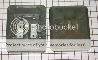
Here is a picture of the Makita LXT battery dock interface.
The driver will reside in a custom plastic enclosure that mounts on top of the Makita Battery dock.
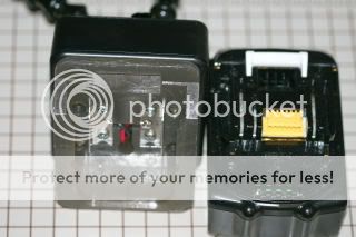
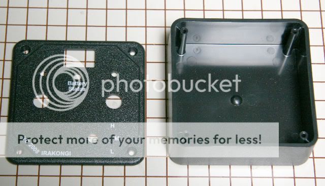
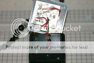
A view with the box open.
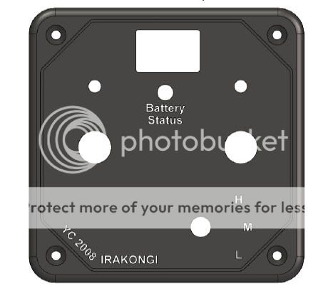
Topside labeling and holes for the box lid.
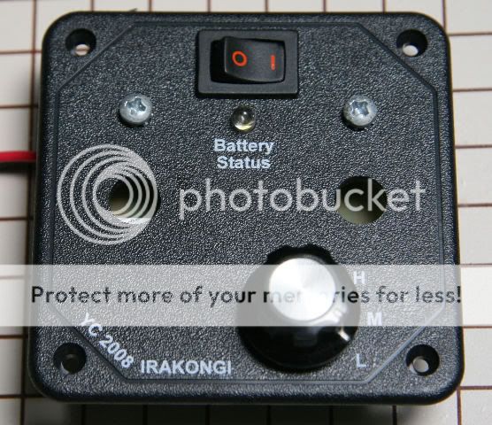
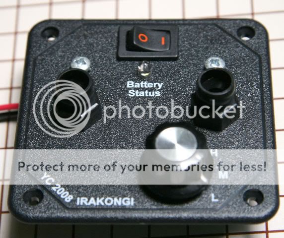
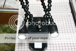
Completed assembly view.
In this configuration there will be a buck driver and a boost driver.
For now they will be called Irakongi-buck and Irakongi-boost for lack of better terminology.
Preliminary specifications:
========================================================
Irakongi-Buck:
Vin Range: 10V-36V
Output Current: Set by one sense resistor (default 1A)
Maximum Input current: ~3A
Maximum Input Power: ~50W
Open Circuit protection: Yes
Thermal foldback: On board sense resistor (can be removed and put on LED heat sink)
Number of Output levels: 3
Output drive levels: 100%, 50%, 20%
Maximum output level: Set by one sense resistor
Output voltage level range: 4V to Vin-1V.
Board Dimensions: 2.3" X 2.1"
Price: TBD
Availability: hand built protos over the next few months until demand warrants production
Irakongi-Boost:
Vin Range: 10V-36V
Output Current: up to 3A
Maximum Input Power: 50W
Maximum Output Voltage:~50V
Open Circuit protection: Yes
Thermal foldback: On board sense resistor (can be removed and put on LED heat sink)
Number of Output levels: 3
Output drive levels: 100%, 50%, 20%
Maximum output level: Set by one sense resistor
Board Dimensions: 2.3" X 2.1"
Price: TBD
Availability: hand built protos over the next few months until demand warrants production
Box dimensions:
3.3" X 3.3" X 1.25"
Board dimensions:
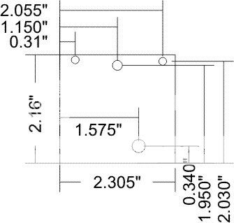
Rotary switch panel hole size: 0.26"
LED mounting hole: 5mm
PCB mounts (2): #6 hardware
========================================================
Example 1: Two 6 die Ostars
First: LED power must be ~40W or less. Two 6 die Ostars @ 1A is around 42W. Close enough.
Next: Determine the Vf of the LED string. Two Ostars ~= 21*2 or 42V. Since 42V is less than the specification of 50V this is acceptable.
Next: Buck or Boost? What battery will you be using? In this example we will be going with the Makita LXT 18V power pack. Maximum is 21V and minimum is around 16V. For both ends of the power pack are less than the Vf of the LED string we need the Irakongi-Boost driver.
I would mount the thermal sensor to the LED heatsink for thermal foldback.
(Note: If each LED are in different heads or heatsink, mount the sensor to one or the other).
Example 2: Two P7 LEDs.
Two P7s at 3A (4V Vf) is 24W.
If Battery source is the Makita LXT (16-21V) we need the Irakongi-buck converter. Change the sense resistor for a 3A output max output.
Again I would mount the thermal sensor to the LED array or heatsink for LED thermal foldback.
Example 3: 12 Cree LEDs @ 1A. Something like 10 whites and two reds might give a good high CRI LED cluster. This configuration is basically identical to the two 6 die Ostars.
=====================================================
The driver will most likely come in the box shown since the three level switch that is mounted to the PCB needs to mount to something. The box provides mechanical mounting of the PCB and can easily be adapted to ones individuals needs. The box bottom is blank. Mounting to the Makita dock requires drilling out the appropriate holes to mount the box to the Makita dock.
Example 1 and 3 could be run off a 12V power supply, vehicle cigarette light er plug or off a 24V wall adaptor as well as the Makita LXT battery.
Example 2 could run off the Dewalt 36V power pack as well as the Makita LXT power pack.
related Links:
Makita LXT with Dual Tri-Rebel head
Wayne
Here is a picture of the Makita LXT battery dock interface.

The driver will reside in a custom plastic enclosure that mounts on top of the Makita Battery dock.

A view with the box open.

Topside labeling and holes for the box lid.

Completed assembly view.

In this configuration there will be a buck driver and a boost driver.
For now they will be called Irakongi-buck and Irakongi-boost for lack of better terminology.
Preliminary specifications:
========================================================
Irakongi-Buck:
Vin Range: 10V-36V
Output Current: Set by one sense resistor (default 1A)
Maximum Input current: ~3A
Maximum Input Power: ~50W
Open Circuit protection: Yes
Thermal foldback: On board sense resistor (can be removed and put on LED heat sink)
Number of Output levels: 3
Output drive levels: 100%, 50%, 20%
Maximum output level: Set by one sense resistor
Output voltage level range: 4V to Vin-1V.
Board Dimensions: 2.3" X 2.1"
Price: TBD
Availability: hand built protos over the next few months until demand warrants production
Irakongi-Boost:
Vin Range: 10V-36V
Output Current: up to 3A
Maximum Input Power: 50W
Maximum Output Voltage:~50V
Open Circuit protection: Yes
Thermal foldback: On board sense resistor (can be removed and put on LED heat sink)
Number of Output levels: 3
Output drive levels: 100%, 50%, 20%
Maximum output level: Set by one sense resistor
Board Dimensions: 2.3" X 2.1"
Price: TBD
Availability: hand built protos over the next few months until demand warrants production
Box dimensions:
3.3" X 3.3" X 1.25"
Board dimensions:

Rotary switch panel hole size: 0.26"
LED mounting hole: 5mm
PCB mounts (2): #6 hardware
========================================================
Example 1: Two 6 die Ostars
First: LED power must be ~40W or less. Two 6 die Ostars @ 1A is around 42W. Close enough.
Next: Determine the Vf of the LED string. Two Ostars ~= 21*2 or 42V. Since 42V is less than the specification of 50V this is acceptable.
Next: Buck or Boost? What battery will you be using? In this example we will be going with the Makita LXT 18V power pack. Maximum is 21V and minimum is around 16V. For both ends of the power pack are less than the Vf of the LED string we need the Irakongi-Boost driver.
I would mount the thermal sensor to the LED heatsink for thermal foldback.
(Note: If each LED are in different heads or heatsink, mount the sensor to one or the other).
Example 2: Two P7 LEDs.
Two P7s at 3A (4V Vf) is 24W.
If Battery source is the Makita LXT (16-21V) we need the Irakongi-buck converter. Change the sense resistor for a 3A output max output.
Again I would mount the thermal sensor to the LED array or heatsink for LED thermal foldback.
Example 3: 12 Cree LEDs @ 1A. Something like 10 whites and two reds might give a good high CRI LED cluster. This configuration is basically identical to the two 6 die Ostars.
=====================================================
The driver will most likely come in the box shown since the three level switch that is mounted to the PCB needs to mount to something. The box provides mechanical mounting of the PCB and can easily be adapted to ones individuals needs. The box bottom is blank. Mounting to the Makita dock requires drilling out the appropriate holes to mount the box to the Makita dock.
Example 1 and 3 could be run off a 12V power supply, vehicle cigarette light er plug or off a 24V wall adaptor as well as the Makita LXT battery.
Example 2 could run off the Dewalt 36V power pack as well as the Makita LXT power pack.
related Links:
Makita LXT with Dual Tri-Rebel head
Wayne
Last edited:


