
StefanFS
Flashlight Enthusiast
UPDATE 2008-10-13
The driver solutions discussed in this post that are based on AMC7135 chips are best suited to be used in conjunction with SSC P7 emitters that are D***I or C***I binned, I at the end means they are 3.25V to 3.5V in forward voltage. If used with D***J or C***J binned emitters regulation and even output may suffer from the higher forward voltage of that binning, 3.5V-3.75V. A better choice for D***J emitters are buck drivers, eg. the driver made by user Der Wichtel.
The output from the drivers in this post are ~3.7V and work best with D***I or C***I binned SSC P7. When matched with one big LiION cell, three good quality
D-size NiMH cells or four AA/C NiMH cells these drivers are a very good choice and have very high efficiency.
Update 2009-02-05
The corresponding build with Cree MC-E can be found here:
https://www.candlepowerforums.com/threads/212835
I particularly like the 2D Mag with 2S2P wired MC-E. That's a more versatile solution.
I have been asked about how I modded my SSC P7 Maglites, especially the driver solution I'm using. The basis of the mod is the classic Maglite with heatsink insert from H22A/Litemania/The Sandwich Shoppe with an Luxeon/SSC/CREE on it and a driver somewhere below the heatsink. You cut the bulb holder pedestal off and solder the leads for the emitter directly to the contact points on the internal switch.
Like this, link to basic Magmod:
https://www.candlepowerforums.com/threads/167866
The driver solution I use is conceived by user NetKidz, schematics can be found here:
https://www.candlepowerforums.com/threads/192677
Pic taken from NetKidz thread:
The driver consists of one 16 mode 1A driver with a slave board that contribute ~1.4A. In total ~2.4A. I like it since the multimode driver have three user interface groups, one is low-med-high. This runs best on three or four big NiMH cells or one big LiION cell.
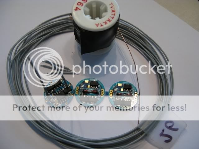
What's needed, besides one Maglite and a heatsink. One C-bin SSC P7 emitter, drivers and some teflon wire:
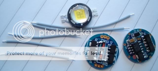
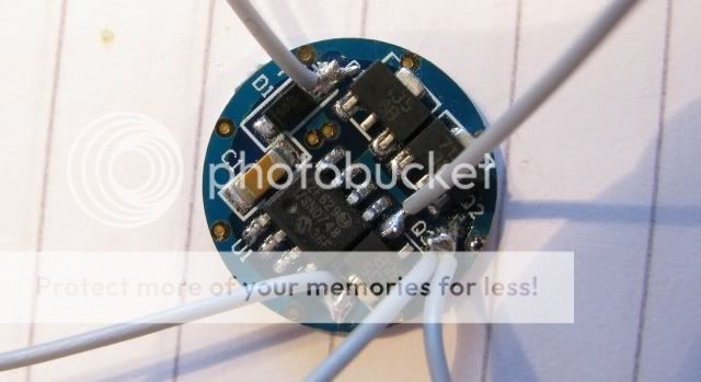
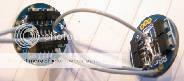
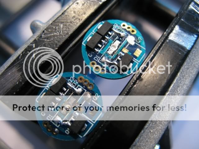
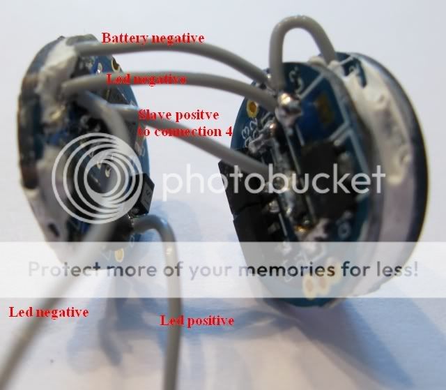
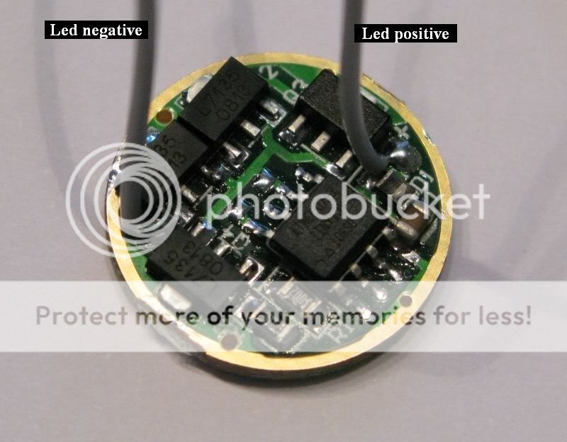
Preparing the drivers, first pic is the multimode driver, wire going up left is led + and wire going down right is led -. Second pic is the slave board. The third pic shows how to connect them. Battery + connects to the + pad on the multimode drivers underside and battery - to the ring of the multimode driver:

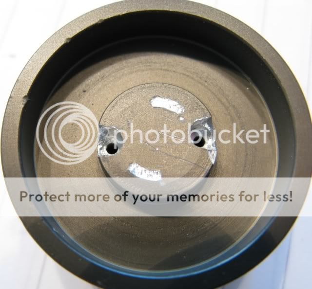
It's necessary to dremel the emitter guides from my H22A heatsink, I also drilled the holes larger with a 3 mm drill bit. Then I opened the drilled holes with my dremel to make space for the emitter legs & leads. I used a milling tip for this. This guide was produced before dedicated SSC P7 heatsinks were available. Now several vendors sell heatsinks for P7 emitters so the dremel work is no longer necessary.
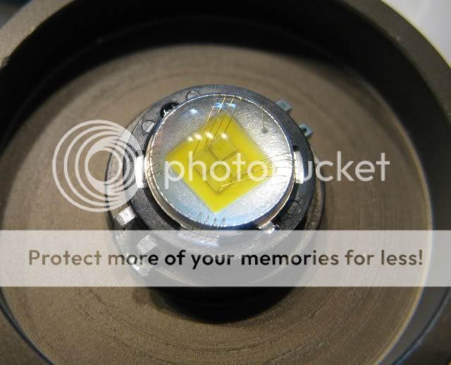
Glueing the emitter to the heatsink with Arctic Alumina epoxy.
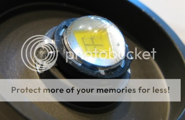
Soldering the teflon wires to the inside of the trimmed emitter legs. I used 26 gauge wire. Make sure that the emitter legs & bare wire ends don't touch the naked metal on the drilled/milled heatsink.
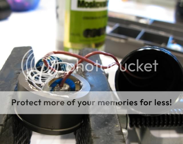
Connecting the battery leads to the multi mode driver. Drivers are glued to the heatsink with Arctic Alumina epoxy and Araldite epoxy. Almost finished. Some heatsink compound (not epoxy or glue) may ease heat transfer from the heatsink to the flashlight body, apply sparingly before inserting the heatsink into the flashlight body.
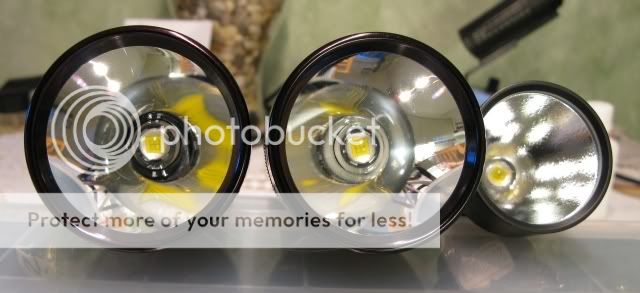
Here it is to the left with two of my other SSC P7 lights. This one is 1D running off one D-size LiION cell. Runtime should be more than two hours on high.
Links to the drivers and heatsink:
Heatsink: https://www.candlepowerforums.com/threads/160483
Multimode driver, 16 mode: http://www.dealextreme.com/details.dx/sku.7612
Multimode driver, 2 mode, my favourite: http://www.kaidomain.com/ProductDetails.aspx?ProductId=1802
AMC7135 1400 mA driver: http://www.dealextreme.com/details.dx/sku.1886
Update 2008-04-27
How to build a high quality, low cost, regulated 3 Ampere driver for your SSC P7 Maglite
This is what you need. Two 1A simple AMC7135 drivers and one 1A AMC7135 multimode driver to control them. Some copper wire, teflon wire 24 or 26 gauge. Three connections are needed between the multimode and the slave sandwich, ~15 mm each. Two 5-7 mm pieces of copper wire to connect battery negative and battery positive between boards on the slave sandwich. One 10 mm piece of teflon wire to connect led negative between boards on the slave sandwich. Two pieces of 20-30 mm teflon wire for connection to the led from the multimode board.
Preparing the boards for the slave sandwich. Removing diodes and making sure connections are made between all AMC7135 chips with solder.
Soldering some copper wire jumpers in place of the diodes.
Making the sandwich. Battery negative is connnected on the edge with copper wire soldered between the boards, the ring around the boards. Not seen is a similar piece of copper wire going from center positive to the other boards center postive (if you miss this it will only give you 2.0A). A short piece of teflon wire going from led negative to led negative.
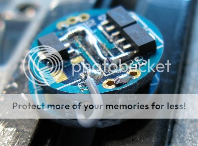
Preparing the multimode driver.
1 will go to battery negative on the slave sandwich.
2 will go to led negative on the slave sandwich.
3 will go to emitter negative.
4 will go to center positive on the top board of the slave sandwich.
5 is going to led positive.
Battery negative and positive connect to the underside of this driver,
negative to the ring and positive to the center.
To illustrate the connections.
This is mounted in a 2D Maglite, options are 3 C size NiMH with some modding or one D-szi LiION cell and one spacer. The difference between 2.4A drive current and 3A is a few thousand lux in throw, ~20 000 versus ~25 000 lux. The big drawback is shorter runtime and more heat. Going from 2.4A to 3A will cut runtime dramatically.
Update 2008-05-03
Today I ran a small unscientific experiment with two of my regulated Maglites, both are 1D using unprotected D LiION cells for power. One has an AMC7135 multimode driver set to 2.4A, the other one has an AMC7135 multimode driver set to 3A. Both have H22A heatsinks with some thermal compound between it and the body, short gold plated springs and UCL-lenses. Both Mags were just laying on the the table, no cooling or even holding in my hand. This test only about heat, not runtime. The runtimes are much longer than what is used here to test heat transfer and heat managment.
After 30 minutes the 2.4A Mag is 36.2 Celsius on the outer side of the head, battery voltage is down to 3.94 V from 4.05 V. Output was a steady 21 300 in throw at one metre, a flatline during the whole test.
After 30 minutes the 3.0A Mag is 39.1 degrees Celsius on the outer side of the head, battery voltage is down to 3.89 V from 4.05 V. Output was a steady 25 800 in throw at one metre, a flatline during the whole test.
So my unscientific feeling is that the drivers I use are top notch, that my lights have working thermal transfer, that the SCC P7 emitters in these two lights can handle heat very well and that they have respectable runtimes.

A word of caution. When using an SSC P7 with AMC7135 drivers and an in voltage exceeding 4.5Volt the temperatures will be considerably higher. These drivers are supposed to be used with max 4.5 Volt as they are the most efficient then.
Update 2008-07-12
Beamshots with the lights discussed in this post.
MRV SSC P7s. Lots of different SSC P7 beamshots!
https://www.candlepowerforums.com/threads/202014
SSC P7 beamshots. Mag & Tiablo A8 SSC P7!
https://www.candlepowerforums.com/threads/198549
SSC P7 Mag against OSRAM 64440 Mag & RaidFire Spear. 95-250 m beamshots!
https://www.candlepowerforums.com/threads/192740
Update 2008-10-28
I did a runtime test on one of my 1D Mags with the above multimode driver, an SSC P7 DSWOI (3.25-3.50V) emitter driven by one unprotected 5000 mAh D-size LiION cell. The unprotected cell is ok to use in this build because output dims noticeably when voltage comes near 3V, then you just change to a fresh cell. I think this driver is a big improvement over using direct drive in one cell LiION lights with C/D***I emitters.
Voltage at 45 min.: 3.78V. Voltage at 90 min.:3.66V. Voltage at 130 min.: 2.89V. At 130 min. the light is very dim.

Update 2009-05-07
How to adapt the spring an tailcap to use 4 x C-size cells.
I use a length of pvc pipe thats 32 mm OD and have an ID that accepts C NiMH cells, eg. 27 mm.
I cut the spring and deanodize the inner part of the tailcap. I use lye and hot water for this, lye is toxic and highly corrosive, it will burn skin and eyes and it stinks, so be careful. Lye (sodium hydroxide) can be found in drain cleaner other such products.

Cut the spring like this, one little piece at a time until it fits in the tailcap. It's trial and error.

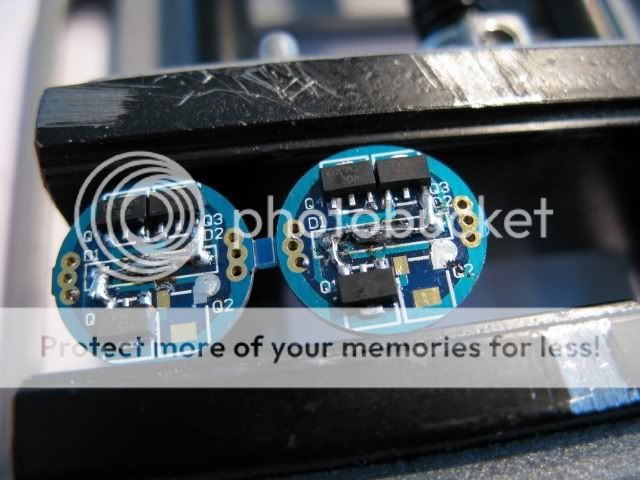
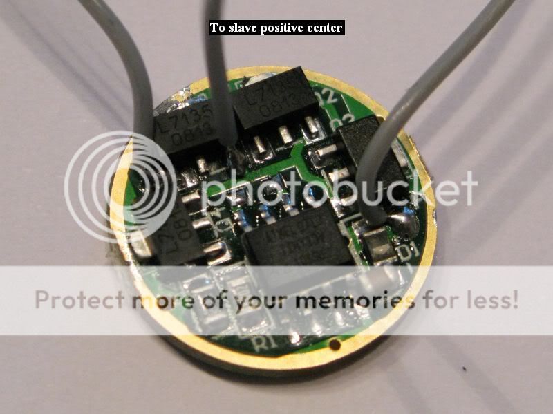
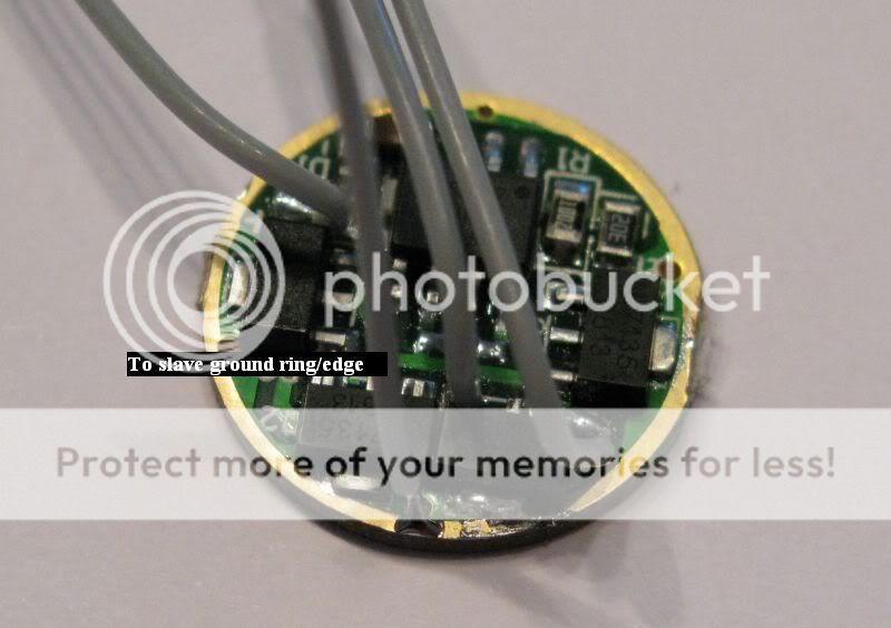
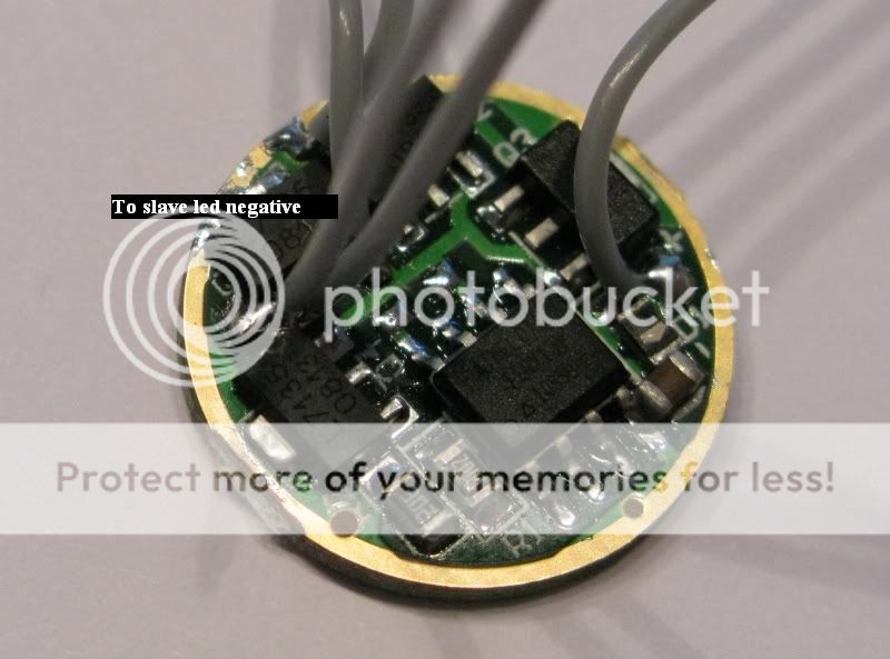
How to connect one of the newer variants of multimode driver
Note that I have popualted an empty space for an additional AMC7135 chip to get 2.8A with just two boards. Even without the additional chip the soldering points are the same. There is at least one more variety of the multimode driver out there, just follow the general rule of connecting as seen here. The last in series AMC735 VDD leg (the one with a trace going to it) on the multimode connects to slave board positive center on all boards I have seen to so far.
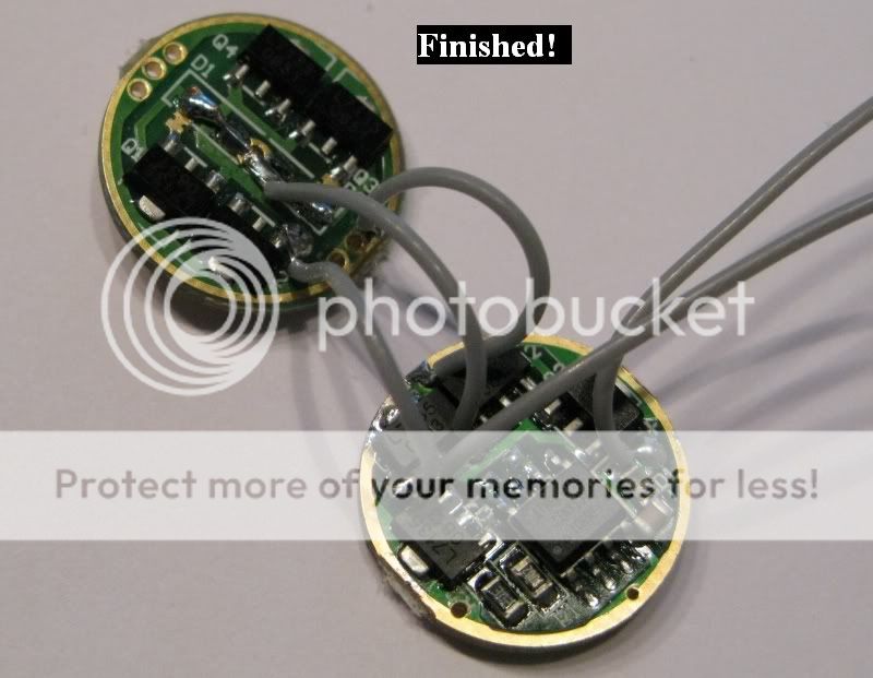
The 1A multimode really does give you 1.4A with an additional AMC7135 chip:

Stefan
The driver solutions discussed in this post that are based on AMC7135 chips are best suited to be used in conjunction with SSC P7 emitters that are D***I or C***I binned, I at the end means they are 3.25V to 3.5V in forward voltage. If used with D***J or C***J binned emitters regulation and even output may suffer from the higher forward voltage of that binning, 3.5V-3.75V. A better choice for D***J emitters are buck drivers, eg. the driver made by user Der Wichtel.
The output from the drivers in this post are ~3.7V and work best with D***I or C***I binned SSC P7. When matched with one big LiION cell, three good quality
D-size NiMH cells or four AA/C NiMH cells these drivers are a very good choice and have very high efficiency.
Update 2009-02-05
The corresponding build with Cree MC-E can be found here:
https://www.candlepowerforums.com/threads/212835
I particularly like the 2D Mag with 2S2P wired MC-E. That's a more versatile solution.
----------------------------------------
I have been asked about how I modded my SSC P7 Maglites, especially the driver solution I'm using. The basis of the mod is the classic Maglite with heatsink insert from H22A/Litemania/The Sandwich Shoppe with an Luxeon/SSC/CREE on it and a driver somewhere below the heatsink. You cut the bulb holder pedestal off and solder the leads for the emitter directly to the contact points on the internal switch.
Like this, link to basic Magmod:
https://www.candlepowerforums.com/threads/167866
The driver solution I use is conceived by user NetKidz, schematics can be found here:
https://www.candlepowerforums.com/threads/192677
Pic taken from NetKidz thread:
The driver consists of one 16 mode 1A driver with a slave board that contribute ~1.4A. In total ~2.4A. I like it since the multimode driver have three user interface groups, one is low-med-high. This runs best on three or four big NiMH cells or one big LiION cell.
What's needed, besides one Maglite and a heatsink. One C-bin SSC P7 emitter, drivers and some teflon wire:
Preparing the drivers, first pic is the multimode driver, wire going up left is led + and wire going down right is led -. Second pic is the slave board. The third pic shows how to connect them. Battery + connects to the + pad on the multimode drivers underside and battery - to the ring of the multimode driver:
It's necessary to dremel the emitter guides from my H22A heatsink, I also drilled the holes larger with a 3 mm drill bit. Then I opened the drilled holes with my dremel to make space for the emitter legs & leads. I used a milling tip for this. This guide was produced before dedicated SSC P7 heatsinks were available. Now several vendors sell heatsinks for P7 emitters so the dremel work is no longer necessary.
Glueing the emitter to the heatsink with Arctic Alumina epoxy.
Soldering the teflon wires to the inside of the trimmed emitter legs. I used 26 gauge wire. Make sure that the emitter legs & bare wire ends don't touch the naked metal on the drilled/milled heatsink.
Connecting the battery leads to the multi mode driver. Drivers are glued to the heatsink with Arctic Alumina epoxy and Araldite epoxy. Almost finished. Some heatsink compound (not epoxy or glue) may ease heat transfer from the heatsink to the flashlight body, apply sparingly before inserting the heatsink into the flashlight body.
Here it is to the left with two of my other SSC P7 lights. This one is 1D running off one D-size LiION cell. Runtime should be more than two hours on high.
Links to the drivers and heatsink:
Heatsink: https://www.candlepowerforums.com/threads/160483
Multimode driver, 16 mode: http://www.dealextreme.com/details.dx/sku.7612
Multimode driver, 2 mode, my favourite: http://www.kaidomain.com/ProductDetails.aspx?ProductId=1802
AMC7135 1400 mA driver: http://www.dealextreme.com/details.dx/sku.1886
Update 2008-04-27
How to build a high quality, low cost, regulated 3 Ampere driver for your SSC P7 Maglite
This is what you need. Two 1A simple AMC7135 drivers and one 1A AMC7135 multimode driver to control them. Some copper wire, teflon wire 24 or 26 gauge. Three connections are needed between the multimode and the slave sandwich, ~15 mm each. Two 5-7 mm pieces of copper wire to connect battery negative and battery positive between boards on the slave sandwich. One 10 mm piece of teflon wire to connect led negative between boards on the slave sandwich. Two pieces of 20-30 mm teflon wire for connection to the led from the multimode board.
Preparing the boards for the slave sandwich. Removing diodes and making sure connections are made between all AMC7135 chips with solder.
Soldering some copper wire jumpers in place of the diodes.
Making the sandwich. Battery negative is connnected on the edge with copper wire soldered between the boards, the ring around the boards. Not seen is a similar piece of copper wire going from center positive to the other boards center postive (if you miss this it will only give you 2.0A). A short piece of teflon wire going from led negative to led negative.
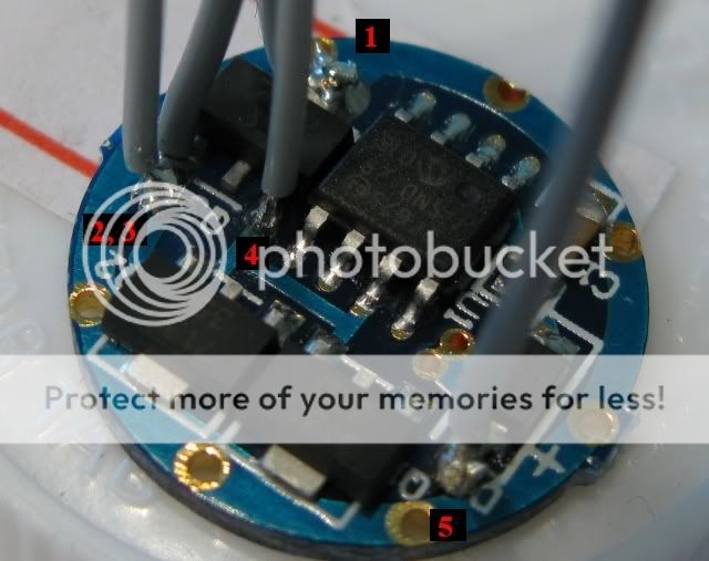
Preparing the multimode driver.
1 will go to battery negative on the slave sandwich.
2 will go to led negative on the slave sandwich.
3 will go to emitter negative.
4 will go to center positive on the top board of the slave sandwich.
5 is going to led positive.
Battery negative and positive connect to the underside of this driver,
negative to the ring and positive to the center.
To illustrate the connections.
This is mounted in a 2D Maglite, options are 3 C size NiMH with some modding or one D-szi LiION cell and one spacer. The difference between 2.4A drive current and 3A is a few thousand lux in throw, ~20 000 versus ~25 000 lux. The big drawback is shorter runtime and more heat. Going from 2.4A to 3A will cut runtime dramatically.
Update 2008-05-03
Today I ran a small unscientific experiment with two of my regulated Maglites, both are 1D using unprotected D LiION cells for power. One has an AMC7135 multimode driver set to 2.4A, the other one has an AMC7135 multimode driver set to 3A. Both have H22A heatsinks with some thermal compound between it and the body, short gold plated springs and UCL-lenses. Both Mags were just laying on the the table, no cooling or even holding in my hand. This test only about heat, not runtime. The runtimes are much longer than what is used here to test heat transfer and heat managment.
After 30 minutes the 2.4A Mag is 36.2 Celsius on the outer side of the head, battery voltage is down to 3.94 V from 4.05 V. Output was a steady 21 300 in throw at one metre, a flatline during the whole test.
After 30 minutes the 3.0A Mag is 39.1 degrees Celsius on the outer side of the head, battery voltage is down to 3.89 V from 4.05 V. Output was a steady 25 800 in throw at one metre, a flatline during the whole test.
So my unscientific feeling is that the drivers I use are top notch, that my lights have working thermal transfer, that the SCC P7 emitters in these two lights can handle heat very well and that they have respectable runtimes.
A word of caution. When using an SSC P7 with AMC7135 drivers and an in voltage exceeding 4.5Volt the temperatures will be considerably higher. These drivers are supposed to be used with max 4.5 Volt as they are the most efficient then.
Update 2008-07-12
Beamshots with the lights discussed in this post.
MRV SSC P7s. Lots of different SSC P7 beamshots!
https://www.candlepowerforums.com/threads/202014
SSC P7 beamshots. Mag & Tiablo A8 SSC P7!
https://www.candlepowerforums.com/threads/198549
SSC P7 Mag against OSRAM 64440 Mag & RaidFire Spear. 95-250 m beamshots!
https://www.candlepowerforums.com/threads/192740
Update 2008-10-28
I did a runtime test on one of my 1D Mags with the above multimode driver, an SSC P7 DSWOI (3.25-3.50V) emitter driven by one unprotected 5000 mAh D-size LiION cell. The unprotected cell is ok to use in this build because output dims noticeably when voltage comes near 3V, then you just change to a fresh cell. I think this driver is a big improvement over using direct drive in one cell LiION lights with C/D***I emitters.
Voltage at 45 min.: 3.78V. Voltage at 90 min.:3.66V. Voltage at 130 min.: 2.89V. At 130 min. the light is very dim.
Update 2009-05-07
How to adapt the spring an tailcap to use 4 x C-size cells.
I use a length of pvc pipe thats 32 mm OD and have an ID that accepts C NiMH cells, eg. 27 mm.
I cut the spring and deanodize the inner part of the tailcap. I use lye and hot water for this, lye is toxic and highly corrosive, it will burn skin and eyes and it stinks, so be careful. Lye (sodium hydroxide) can be found in drain cleaner other such products.
Cut the spring like this, one little piece at a time until it fits in the tailcap. It's trial and error.
How to connect one of the newer variants of multimode driver
Note that I have popualted an empty space for an additional AMC7135 chip to get 2.8A with just two boards. Even without the additional chip the soldering points are the same. There is at least one more variety of the multimode driver out there, just follow the general rule of connecting as seen here. The last in series AMC735 VDD leg (the one with a trace going to it) on the multimode connects to slave board positive center on all boards I have seen to so far.
The 1A multimode really does give you 1.4A with an additional AMC7135 chip:
Stefan
Last edited:

")