Kestrel
Flashaholic
Modding a SureFire L2 with the MC-E (still in process)
This is sort of a combination How-to, How-do-I-do-it?, and How-it-went thread. This is going to be a work in progress for a while, as I'm just starting out on it - any input from the many experts here would be most appreciated.
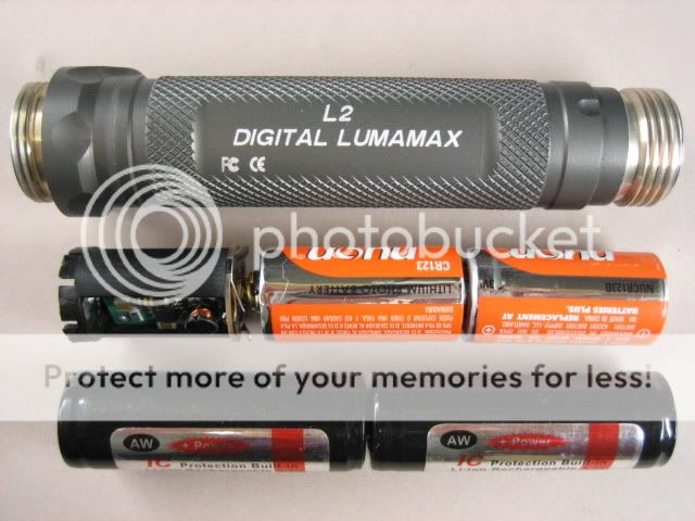
I've owned a SureFire L2 for ~3 years now (it was one of my first two SureFires), and to tell the truth I've never been 100% happy with it. I very much like the UI of the L1/L2 series, but was never all that enamored of the Luxeon V emitter in the L2. 100 lumens sounded OK at the time, but being a rather floody overall design, there seldom seemed to be enough lux for me, especially coming from a flashlight of that size (6.1" in length, approximately equal to my 3xCR123 SF C3 / M60). In addition, I've found that the slightly greenish tint common to the LuxV was a bit distracting.
I was inspired to pursue this mod after reading up on some related threads featuring the transplant of the Cree MC-E into a SureFire, particularly this excellent L2 / MC-E thread by Energie, which included lots of helpful pics:
Surefire L2 with Cree MC-E
I also read these other threads (not necessarily L2 modding threads) for additional background info:
KL4 neutral white MC-E modding service
SureFire KL4 MC-E mod
Surefire L4 (KL4) with Cree MC-E
One Surefire L4 with MC-E emitter
(This last one is only a sale thread by AaronM for L2's & L4's modded with MC-E's, but still included useful info including beamshots showing various MC-E tints)
It seems like the SF L2 is a great candidate for the MC-E:

Boring the body:
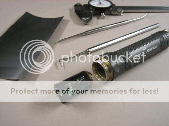
The first thing I need to get done is to very slightly bore the body from 0.660" (16.8mm) ID to 0.674" (17.1mm) for 1x17670, as the diameter of the AW 17670 is 17.02 +- 0.05mm. (Edit: I just rec'd the AW17670 that I'll be using for this light and its max OD is 0.669" = 16.99mm.) This will take the minimum wall thickness of the L2 body (measured at the o-ring groove) from (0.727"-0.660")/2 = 0.0335" down to 0.0265". As a point of reference, "18mm boring" the SureFire 6P takes the minimum wall thickness from 0.042" to approximately 0.018"-0.015".
I chose to go with 1x17670 rather than 1x14670 (which wouldn't require boring) becuase my calcs show that 1x 17670 results in ~10-15% more total watt-hours compared to 2xCR123 primaries, for a configuration of the same overall length. From my (very) limited experience with 18mm boring & related cell measurements, boring the diameter 0.1mm oversize seems to be adequate. Worst-case, I can just peel off the silver label from the AW 17670 if I get some oversize cells.
A second O-ring groove:
One detail that is important to me will be adding a second O-ring groove so that the existing O-ring can be placed slightly further from the tail:
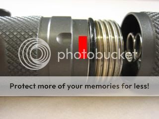

The reason for this is not to add a second O-ring (so as to gain additional water resistance), but instead to permit the tailcap threads to engage prior to getting the tailcap over the o-ring (which would be slightly further away from the tailcap after this modification). I've always been slightly annoyed when installing the tailcap on this light (as well as with my SF L1), trying to engage the threads while trying at the exact same time to get the lip of the tailcap over the o-ring. I prefer the tailcap relationship on the SureFire P/C series, where the tailcap threads engage prior to having to compress the O-ring under the tailcap. Just a small detail, but since it's going to be on the lathe anyway, adding this will be a nice detail IMO. I'm confident that there will be enough remaining overlap so that the O-ring will be fully covered & protected in its new location.
In addition to the above...
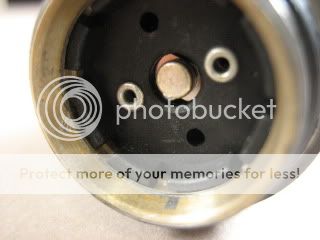
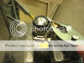
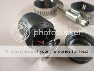
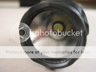
So after I open the head & remove the existing LED, the existing heatsink needs to be slightly modified (by enlarging the wire routing holes for the extra pair of wires that are required for the 4-die MC-E). In addition, I also gather that I'll have to have the other side of the head very slightly milled out to permit optimum focus of the MC-E in the reflector. But that's a bit down the line from where I'm at for the moment...
And the beamshots:
Initial (i.e. the unmodified light):
Normal exposure:
SF L2 (low) _______________ SF L2 (High) ______________ Malkoff M60 (as a reference)


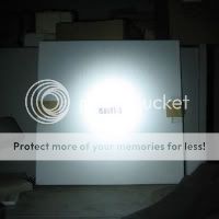
Underexposed:
SF L2 (low) _______________ SF L2 (High) ______________ Malkoff M60 (as a reference)


This is sort of a combination How-to, How-do-I-do-it?, and How-it-went thread. This is going to be a work in progress for a while, as I'm just starting out on it - any input from the many experts here would be most appreciated.
I've owned a SureFire L2 for ~3 years now (it was one of my first two SureFires), and to tell the truth I've never been 100% happy with it. I very much like the UI of the L1/L2 series, but was never all that enamored of the Luxeon V emitter in the L2. 100 lumens sounded OK at the time, but being a rather floody overall design, there seldom seemed to be enough lux for me, especially coming from a flashlight of that size (6.1" in length, approximately equal to my 3xCR123 SF C3 / M60). In addition, I've found that the slightly greenish tint common to the LuxV was a bit distracting.
I was inspired to pursue this mod after reading up on some related threads featuring the transplant of the Cree MC-E into a SureFire, particularly this excellent L2 / MC-E thread by Energie, which included lots of helpful pics:
Surefire L2 with Cree MC-E
I also read these other threads (not necessarily L2 modding threads) for additional background info:
KL4 neutral white MC-E modding service
SureFire KL4 MC-E mod
Surefire L4 (KL4) with Cree MC-E
One Surefire L4 with MC-E emitter
(This last one is only a sale thread by AaronM for L2's & L4's modded with MC-E's, but still included useful info including beamshots showing various MC-E tints)
It seems like the SF L2 is a great candidate for the MC-E:
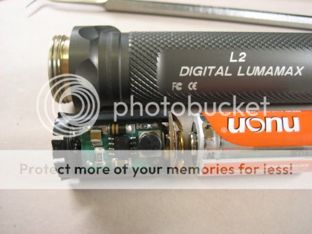
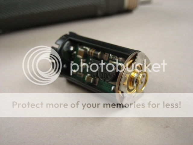
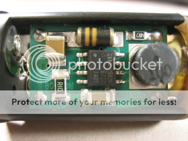
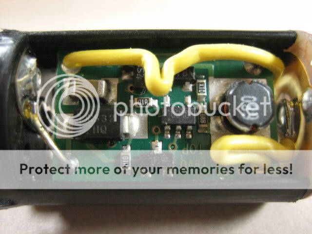
- the existing SF L2 driver is a very good match for an MC-E wired 2s2p
- since the existing driver is a 'boost' driver, it will work well with 1x LiIon (@ 3.7v) as well as still retaining compatibility with 2x CR123 (@ ~5.0v) for backup.
- the existing (& quite sizeable) heatsink in the L2 can be used with only minor modification
- the existing reflector is a relatively good match to the new emitter, particularly when the MC-E package is shimmed up ~1.4mm from the existing heatsink.


Boring the body:
The first thing I need to get done is to very slightly bore the body from 0.660" (16.8mm) ID to 0.674" (17.1mm) for 1x17670, as the diameter of the AW 17670 is 17.02 +- 0.05mm. (Edit: I just rec'd the AW17670 that I'll be using for this light and its max OD is 0.669" = 16.99mm.) This will take the minimum wall thickness of the L2 body (measured at the o-ring groove) from (0.727"-0.660")/2 = 0.0335" down to 0.0265". As a point of reference, "18mm boring" the SureFire 6P takes the minimum wall thickness from 0.042" to approximately 0.018"-0.015".
I chose to go with 1x17670 rather than 1x14670 (which wouldn't require boring) becuase my calcs show that 1x 17670 results in ~10-15% more total watt-hours compared to 2xCR123 primaries, for a configuration of the same overall length. From my (very) limited experience with 18mm boring & related cell measurements, boring the diameter 0.1mm oversize seems to be adequate. Worst-case, I can just peel off the silver label from the AW 17670 if I get some oversize cells.
A second O-ring groove:
One detail that is important to me will be adding a second O-ring groove so that the existing O-ring can be placed slightly further from the tail:


The reason for this is not to add a second O-ring (so as to gain additional water resistance), but instead to permit the tailcap threads to engage prior to getting the tailcap over the o-ring (which would be slightly further away from the tailcap after this modification). I've always been slightly annoyed when installing the tailcap on this light (as well as with my SF L1), trying to engage the threads while trying at the exact same time to get the lip of the tailcap over the o-ring. I prefer the tailcap relationship on the SureFire P/C series, where the tailcap threads engage prior to having to compress the O-ring under the tailcap. Just a small detail, but since it's going to be on the lathe anyway, adding this will be a nice detail IMO. I'm confident that there will be enough remaining overlap so that the O-ring will be fully covered & protected in its new location.
In addition to the above...
So after I open the head & remove the existing LED, the existing heatsink needs to be slightly modified (by enlarging the wire routing holes for the extra pair of wires that are required for the 4-die MC-E). In addition, I also gather that I'll have to have the other side of the head very slightly milled out to permit optimum focus of the MC-E in the reflector. But that's a bit down the line from where I'm at for the moment...
And the beamshots:
Initial (i.e. the unmodified light):
Normal exposure:
SF L2 (low) _______________ SF L2 (High) ______________ Malkoff M60 (as a reference)


Underexposed:
SF L2 (low) _______________ SF L2 (High) ______________ Malkoff M60 (as a reference)


Last edited:


